EP2072918A1 - Temperature regulating fluid circuit - Google Patents
Temperature regulating fluid circuit Download PDFInfo
- Publication number
- EP2072918A1 EP2072918A1 EP08172068A EP08172068A EP2072918A1 EP 2072918 A1 EP2072918 A1 EP 2072918A1 EP 08172068 A EP08172068 A EP 08172068A EP 08172068 A EP08172068 A EP 08172068A EP 2072918 A1 EP2072918 A1 EP 2072918A1
- Authority
- EP
- European Patent Office
- Prior art keywords
- circuit
- duct
- input
- generator
- channel
- Prior art date
- Legal status (The legal status is an assumption and is not a legal conclusion. Google has not performed a legal analysis and makes no representation as to the accuracy of the status listed.)
- Withdrawn
Links
- 238000002156 mixing Methods 0.000 claims description 67
- 239000012530 fluid Substances 0.000 claims description 62
- 238000011144 upstream manufacturing Methods 0.000 claims description 9
- 235000021183 entrée Nutrition 0.000 description 13
- 239000000203 mixture Substances 0.000 description 11
- 208000031968 Cadaver Diseases 0.000 description 8
- 238000009434 installation Methods 0.000 description 7
- 238000004064 recycling Methods 0.000 description 7
- 238000010438 heat treatment Methods 0.000 description 5
- 230000003071 parasitic effect Effects 0.000 description 3
- LYCAIKOWRPUZTN-UHFFFAOYSA-N Ethylene glycol Chemical compound OCCO LYCAIKOWRPUZTN-UHFFFAOYSA-N 0.000 description 2
- 230000007423 decrease Effects 0.000 description 2
- 230000004048 modification Effects 0.000 description 2
- 238000012986 modification Methods 0.000 description 2
- 241001249696 Senna alexandrina Species 0.000 description 1
- 239000000956 alloy Substances 0.000 description 1
- 229910045601 alloy Inorganic materials 0.000 description 1
- 238000009833 condensation Methods 0.000 description 1
- 230000005494 condensation Effects 0.000 description 1
- 238000001816 cooling Methods 0.000 description 1
- 238000010908 decantation Methods 0.000 description 1
- 230000003247 decreasing effect Effects 0.000 description 1
- 238000007872 degassing Methods 0.000 description 1
- 238000009795 derivation Methods 0.000 description 1
- 230000000694 effects Effects 0.000 description 1
- 238000011067 equilibration Methods 0.000 description 1
- 239000000446 fuel Substances 0.000 description 1
- 239000008240 homogeneous mixture Substances 0.000 description 1
- WGCNASOHLSPBMP-UHFFFAOYSA-N hydroxyacetaldehyde Natural products OCC=O WGCNASOHLSPBMP-UHFFFAOYSA-N 0.000 description 1
- 239000007788 liquid Substances 0.000 description 1
- 238000004519 manufacturing process Methods 0.000 description 1
- 238000000034 method Methods 0.000 description 1
- 210000000056 organ Anatomy 0.000 description 1
- 244000045947 parasite Species 0.000 description 1
- XLYOFNOQVPJJNP-UHFFFAOYSA-N water Substances O XLYOFNOQVPJJNP-UHFFFAOYSA-N 0.000 description 1
Images


Classifications
-
- F—MECHANICAL ENGINEERING; LIGHTING; HEATING; WEAPONS; BLASTING
- F24—HEATING; RANGES; VENTILATING
- F24D—DOMESTIC- OR SPACE-HEATING SYSTEMS, e.g. CENTRAL HEATING SYSTEMS; DOMESTIC HOT-WATER SUPPLY SYSTEMS; ELEMENTS OR COMPONENTS THEREFOR
- F24D19/00—Details
- F24D19/10—Arrangement or mounting of control or safety devices
- F24D19/1006—Arrangement or mounting of control or safety devices for water heating systems
- F24D19/1009—Arrangement or mounting of control or safety devices for water heating systems for central heating
-
- F—MECHANICAL ENGINEERING; LIGHTING; HEATING; WEAPONS; BLASTING
- F24—HEATING; RANGES; VENTILATING
- F24D—DOMESTIC- OR SPACE-HEATING SYSTEMS, e.g. CENTRAL HEATING SYSTEMS; DOMESTIC HOT-WATER SUPPLY SYSTEMS; ELEMENTS OR COMPONENTS THEREFOR
- F24D3/00—Hot-water central heating systems
- F24D3/10—Feed-line arrangements, e.g. providing for heat-accumulator tanks, expansion tanks ; Hydraulic components of a central heating system
- F24D3/1091—Mixing cylinders
Definitions
- the invention relates to a temperature control fluid circuit.
- the temperature control installations and circuits conventionally comprise a generator circuit, also called primary circuit, where the generator is located, heat or cold, and a transmitter circuit, or secondary circuit, where the energy transmitter is located, for example a radiator, or a heated floor.
- a generator circuit also called primary circuit
- a transmitter circuit or secondary circuit
- the energy transmitter is located, for example a radiator, or a heated floor.
- Each of the circuits generally comprises a pump.
- bottles breakage pressure also called hydraulic decoupling bottles.
- the circuit according to the invention ensures that the entire fluid of the generator circuit will be dedicated to the transmitter circuit.
- the efficiencies of the installations equipped with bottles with pressure failure are rectified.
- the hydraulic decoupling is always present since the emitter circuit is connected by its inlet and outlet ducts to the bottle breakage pressure and the generator circuit is connected by its input conduit.
- the circuit according to the invention comprises a mixing device providing the connection between the output duct of the generator circuit and the input duct of the emitter circuit.
- This mixing member is configured so as to control the mixing of the fluids from the emitter circuit and the generator circuit, while limiting the disturbances and the return of fluid from the generator circuit to the bottle breakage pressure which would reduce the yield.
- the mixing member advantageously comprises a substantially straight tubular body having a first and a second end respectively forming a first input channel intended to be connected to the input channel of the emitter circuit upstream of the mixing member and a first output channel intended to be connected to the input duct of the emitter circuit downstream of the mixing member.
- the mixing member is positioned at the inlet duct of the emitter circuit and allows the flow of fluid without modification.
- the mixing member preferably comprises a channel forming a second input channel intended to be connected to the output duct of the generator circuit and opening inside the body of the mixing member.
- the channel is formed of two portions, a rectilinear portion passing through the wall of the mixing body and a bent portion lying inside the body of the mixing member and preferably extends in a direction substantially parallel to the longitudinal direction of the body.
- the bent portion has an open end advantageously oriented in the direction of flow of the fluid passing through said body to prevent a portion of the fluid is returned to the bottle breakage pressure.
- the figure 1 represents a temperature control circuit according to the state of the art.
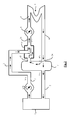
- the figure 2 represents a temperature control fluid circuit according to the invention.
- the figure 3 represents a sectional side view of the mixing member according to the invention.
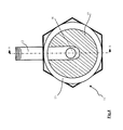
- the figure 4 represents a front view in section of the mixing member according to the invention.
- the figure 1 represents the temperature control fluid circuit according to the state of the art with its disadvantages.
- the generator is heating.
- This circuit conventionally comprises a generator 1, hot or cold, to which is connected at least one inlet duct 2 and an outlet duct 3.
- temperature control circuits use heat transfer fluids such as water, oil or conventional glycol liquids.
- a pump 8 is placed at the outlet duct 3 to generate a flow rate to the fluid.
- the inlet ducts 2 and outlet 3 open into a pressure-breaking bottle 7.
- the pressure-breaking bottle 7 is also connected to a transmitter circuit comprising an emitter 4, for example a heating floor, via an inlet duct 5 connecting the bottle breaks pressure 7 at the transmitter 4 and by an outlet duct 6 connecting the transmitter 4 to the bottle breakage 7.
- a pump 9 is placed at the inlet duct 5 to generate a flow rate to the fluid flowing in the emitter circuit.
- inlet duct 2-5 corresponds to the conduit for bringing the fluid from the bottle breaks pressure 7 to the generator 1 or the transmitter 4.
- outlet duct 3-6 corresponds to the duct allowing bring the fluid from the generator 1 or the emitter 4 to the pressure breaking bottle 7.
- the Applicant has noticed that a significant amount of the fluid leaving the generator circuit at the level of the pressure-breaking bottle 7 is not directed towards the transmitter circuit but returns to the generator circuit. In order to compensate for the lack of flow towards the transmitter circuit, it is necessary that the setpoint temperature of the generator is high. There is therefore a parasitic recycling flow 23 limiting the efficiency of the temperature control circuit.
- the fluid then flows at the transmitter circuit where it has for example a temperature of about 35 ° C.
- the fluid is then directed to the emitter 4 where the heat energy will be released, for example at a radiator or underfloor heating.
- the fluid returns to the bottle breakage pressure 7 by the outlet duct 6 where the fluid has, for example, a temperature of the order of 30 ° C.
- a bypass 25 for directly transferring a portion of the fluid flowing in the outlet duct 6 to the inlet duct 5 of the emitter circuit via a mixing valve 10.
- This system makes it possible to adjust the temperature of the fluid flowing in the inlet duct 5.
- the presence of the mixing valve increases the parasitic flows at the level of the pressure-breaking bottle 7 and therefore reduces the efficiency.
- the fluid arriving from the outlet duct 6 of the emitter circuit at the level of the pressure-breaking bottle 7 will then go towards two destinations: a part of the fluid is directed towards the inlet duct 2 of the generator circuit where it will be heated or another portion of the fluid is directed to the input conduit 5 of the transmitter circuit.
- This last stream is called the emitter recycling stream 24.
- this parasitic recycling stream generator 23 proposes to suppress to allow the loss of energy to be reduced. As a result, the fluid leaving the outlet duct 3 of the generator circuit can be at a lower temperature.
- the present invention represented at figure 2 conventionally comprises a generator 1 an input duct 2 of the generator circuit connecting the Bottle pressure 7 to the generator 1.
- a transmitter circuit comprising a transmitter 4, an inlet duct 5 connecting the pressure breaking bottle 7 to the transmitter 4 and an outlet duct 6 connecting the transmitter 4 to the bottle breaks pressure 7.
- the generator and transmitter circuits may comprise pumps 8 and 9 for generating specific flow rates.
- the output duct 3 of the generator circuit is connected to the input duct 5 of the emitter circuit, which means that the outlet duct 3 of the generator circuit does not open at the level of the pressurized bottle 7 but at the level of the input duct 5 of the transmitter circuit.
- the output duct 3 of the generator circuit and the input duct 5 of the emitter circuit are mutually connected downstream of the breakage bottle 7.
- the outlet duct 3 of the generator circuit opens into the inlet duct 5 of the circuit Transmitter advantageously outside the bottle breakage 7.
- the spurious recycling stream 23 has been removed.
- the circuit according to the invention is particularly simple to manufacture and install. It has a great robustness and limits the modifications to be made to the conventional bottles breakage pressure.
- the output duct 3 of the generator circuit opens directly into the input duct 5 of the emitter circuit.
- the output duct 3 of the generator circuit opens into the input duct 5 of the emitter circuit via an element.
- the connection between the output duct 3 of the generator circuit and the input duct 5 of the emitter circuit is provided by a mixing member 11.
- the mixing member 11 is formed for the connection zone between the output duct 3 of the generator circuit and the input duct 5 of the emitter circuit.
- the outlet duct 3 is directly connected or connected to the inlet duct 5.
- the mixing member 11 is distinct from the breakage bottle 7, the outlet duct 3 of the circuit generator and / or conduit 5 of the transmitter circuit.
- this mixing member 11 comprises a substantially rectilinear tubular body 13 having a first end 14 and a second end 15 respectively forming a first input channel intended to be connected to the input conduit of the emitter circuit 22 upstream of the mixing member, and an output channel intended to be connected to the input duct of the emitter circuit 21 downstream of the mixing member.
- inlet duct of the emitter circuit upstream of the mixing member is understood to mean the portion of the inlet duct 5 located between the mixing member 11 and the pressure breaking bottle 7.
- duct input of the emitter circuit downstream of the mixing member the portion of the inlet duct 5 of the emitter circuit between the emitter 4 and the mixing member 11.
- the mixing member 11 preferably comprises a channel 12 forming a second inlet channel intended to be connected to the outlet duct 3 of the generator circuit and opening into the body 13 of the mixing member 11.
- the generator setpoint temperature can be decreased to be closer to the desired temperature at the transmitter.
- the temperature of the fluid flowing in the outlet duct 3 of the generator circuit has for example a temperature of 50 ° C since all the fluid of the generator is intended for the emitter circuit.
- the temperature of the fluid flowing in the inlet duct 2 of the generator circuit is only at a temperature of 30 ° C. which is much lower than that of the circuit of the state of the art which was 40.degree. ° C.
- the efficiency of the circuit according to the invention is therefore much higher than that of the circuits of the state of the art.
- the mixing valves 10 can be easily used.
- the mixing member 11 according to the invention is arranged in such a way as to obtain the best possible flow of the fluid coming from the outlet duct 3 of the generator circuit and the fluid flowing at the input duct 5 of the emitter circuit. Indeed, it is important that when the fluid from the generator circuit arrives at the level of the mixing member 11, there are not too many disturbances at the level of the flow of the fluid present at the inlet duct. 5 of the transmitter circuit to avoid in particular the return of fluid to the bottle breakage 7.
- the channel 12 comprises a rectilinear portion 19 and a bent portion 20 having an open end opening into the body 13.
- the bent portion 20 extends in a direction substantially parallel to the longitudinal direction of the body 13 and the open end of the bent portion 20 is oriented in the direction of flow of the fluid passing through the body 13.
- This arrangement contributes to bringing the fluid flowing in the outlet duct 3 of the generator circuit in the direction of flow of the fluid flowing in the body 13.
- the two fluids circulate in the same direction which limits the disturbances and allows a good mixture fluids for obtaining a fluid at a uniform temperature from the mixing member 11.
- the median longitudinal axis of the bent portion 20 substantially corresponds to the median longitudinal axis of the body 13 thus making it possible to center the flow of the fluid coming from the outlet duct 3 with respect to the fluid flowing in the body 13.
- the surface 16 of the channel 12 at its open end of the bent portion 20 is substantially equal to the flow surface of the fluid 17 passing through the body 13 along a section of the body 13 at the rectilinear position 19 of the channel 12.
- This ratio has, moreover, the advantage of avoiding the return of fluid to the bottle breakage pressure 7, while limiting fluid turbulence.
- the flow of fluid downstream of the mixing member is substantially laminar.
- the rectilinear portion 19 and the bent portion 20 form a substantially straight angle.
- the diameter of the body 13 of the mixing member 11 is greater than that of the inlet duct 5 of the transmitter circuit. This makes it possible to consider the mixing member 11 as a buffer zone, which favors the mixing of the fluids and allows equilibration of the flow rates.
- the dimensions of the mixing member 11, in particular the diameters of the inlet and outlet channels will be provided as a function of the flow rates of the fluid at the generator and emitter circuits.
- the rectilinear portion 19 of the channel 12 is substantially perpendicular to the longitudinal direction of the body 13.
- the mixing member 11 is removable.
- the mixing member comprises threads at the two input channels and the output channel intended to cooperate with threads located on the upstream portion 22 and the downstream portion 21 of the conduit. input 5 of the transmitter circuit, and on the output duct 3 of the generator circuit.
- the threads are arranged on the outer walls of the mixing member 11.
- the mixing member 11 may be made by foundry processes, cupro-alloy or welded mechanic.
- the circuit according to the invention represented in figure 2 may comprise a mixing valve 10 of the type represented at the level of the figure 1 without this modifying the operation of the invention.
- the mixing valve 10 will advantageously be placed downstream of the mixing member 11 and upstream of the emitter 4 and, preferably, downstream of the mixing member 11 and upstream of the pump 9.
- the circuit according to the invention as well as the mixing member 11 will be particularly suitable in installations using solar thermal energy where it is imperative that the auxiliary generators do not come, by untimely mixtures, warm the circuit of solar energy.
- the pressure breaking bottle 7 may also have additional functions such as decantation and degassing.
Landscapes
- Engineering & Computer Science (AREA)
- Physics & Mathematics (AREA)
- Thermal Sciences (AREA)
- Chemical & Material Sciences (AREA)
- Combustion & Propulsion (AREA)
- Mechanical Engineering (AREA)
- General Engineering & Computer Science (AREA)
- Accessories For Mixers (AREA)
Applications Claiming Priority (1)
| Application Number | Priority Date | Filing Date | Title |
|---|---|---|---|
| FR0760163A FR2925652B1 (fr) | 2007-12-20 | 2007-12-20 | Circuit de fluide de regulation de temperature |
Publications (1)
| Publication Number | Publication Date |
|---|---|
| EP2072918A1 true EP2072918A1 (de) | 2009-06-24 |
Family
ID=39591725
Family Applications (1)
| Application Number | Title | Priority Date | Filing Date |
|---|---|---|---|
| EP08172068A Withdrawn EP2072918A1 (de) | 2007-12-20 | 2008-12-18 | Temperature regulating fluid circuit |
Country Status (2)
| Country | Link |
|---|---|
| EP (1) | EP2072918A1 (de) |
| FR (1) | FR2925652B1 (de) |
Citations (3)
| Publication number | Priority date | Publication date | Assignee | Title |
|---|---|---|---|---|
| DE2817538A1 (de) * | 1978-04-21 | 1979-10-25 | Harald Sobig | Wasserumlauf-zentralheizung |
| DE10102022A1 (de) * | 2000-01-15 | 2001-07-19 | Vaillant Joh Gmbh & Co | Wasserheizanlage |
| EP1760407A1 (de) * | 2005-09-05 | 2007-03-07 | Comfort-Sinusverteiler GmbH | Rohrverteiler für eine Heizungs- oder Kühlanlage |
-
2007
- 2007-12-20 FR FR0760163A patent/FR2925652B1/fr not_active Expired - Fee Related
-
2008
- 2008-12-18 EP EP08172068A patent/EP2072918A1/de not_active Withdrawn
Patent Citations (3)
| Publication number | Priority date | Publication date | Assignee | Title |
|---|---|---|---|---|
| DE2817538A1 (de) * | 1978-04-21 | 1979-10-25 | Harald Sobig | Wasserumlauf-zentralheizung |
| DE10102022A1 (de) * | 2000-01-15 | 2001-07-19 | Vaillant Joh Gmbh & Co | Wasserheizanlage |
| EP1760407A1 (de) * | 2005-09-05 | 2007-03-07 | Comfort-Sinusverteiler GmbH | Rohrverteiler für eine Heizungs- oder Kühlanlage |
Non-Patent Citations (1)
| Title |
|---|
| "DIMENSIONNEMENT DES BOUTEILES DE DECOUPLAGE HYDRAULIQUE", CFP CHAUD FROID PLOMBERIE, EDITIONS PARISIENNES. PARIS, FR, no. 615, 1 July 1999 (1999-07-01), pages 43 - 49, XP000829991, ISSN: 0750-1552 * |
Also Published As
| Publication number | Publication date |
|---|---|
| FR2925652B1 (fr) | 2012-04-13 |
| FR2925652A1 (fr) | 2009-06-26 |
Similar Documents
| Publication | Publication Date | Title |
|---|---|---|
| EP2069620A2 (de) | Vorrichtung zur verteilung einer kühlflüssigkeit in einem kraftfahrzeugmotor | |
| FR3028245A1 (fr) | Circuit d'alimentation en carburant d'un aeronef | |
| FR2890430A1 (fr) | Circuit de refroidissement de l'huile d'une boite de vitesses | |
| FR2925652A1 (fr) | Circuit de fluide de regulation de temperature | |
| EP2655946B1 (de) | Vorrichtung zur steuerung der flussrate eines kühlmittels | |
| FR3074531A1 (fr) | Installation pour une turbomachine | |
| EP1998053A2 (de) | Ejektorpumpe | |
| FR3014488A1 (fr) | Vanne pour circuit carburant d'un moteur d'aeronef | |
| FR2910586A1 (fr) | Vanne thermostatique de regulation d'un fluide, circuit de liquide de refroidissement incorporant une telle vanne et procede de fabrication d'une telle vanne. | |
| EP2306096A1 (de) | Heizsystem für Brauchwasser und Raumheizung mit zwei Wärmequellen | |
| EP3670867A1 (de) | Verbesserte vorrichtung zur regulierung des versorgungsdurchsatzes | |
| EP1188991B1 (de) | Hydraulisches Verteilerventil für kombinierte Heizungsanlage | |
| FR2966576A1 (fr) | Dispositif de circulation d'un fluide caloporteur autour d'un tuyau de transport de fluide, kit pour la realisation et procede d'installation d'un tel dispositif | |
| WO2014167199A1 (fr) | Circuit de refroidissement d'un moteur a combustion interne | |
| EP2461108B1 (de) | Wandheizvorrichtung, Ausstattung zum Aufheizen einer Flüssigkeit, Heizanlage eines Lokals und Anpassungsverfahren einer Wandheizvorrichtung | |
| FR2550605A1 (fr) | Bloc de derivation pour circuit hydraulique, notamment de chauffage | |
| EP3134637B1 (de) | Schaltung zur neuansaugung von blow-by-gas für eine brennkraftmaschine, insbesondere benzinmotor | |
| FR2932845A1 (fr) | Procede et dispositif de refroidissement d'un moteur thermique. | |
| FR2505459A1 (fr) | Ensemble de raccordement entre un generateur de chaleur principal et un generateur d'appoint ou de remplacement, parcourus par un meme fluide caloporteur | |
| FR2924164A1 (fr) | Dispositif amortisseur des pulsations de pression dans un circuit de refroidissement d'un moteur | |
| FR3038368B1 (fr) | Dispositif de regulation d'une temperature d'eau sanitaire et procede de regulation de l'alimentation d'un point de puisage | |
| JP2025115563A (ja) | 給湯器 | |
| EP4726267A1 (de) | Hydraulisches speichermodul mit einer perforierten leitung | |
| FR2956475A3 (fr) | Dispositif permettant d'utiliser un chauffe-eau standard (cumulus) non modifie interieurement comme moyen de stockage d'eau chaude en provenance d'un panneau solaire ou d'une pompe a chaleur | |
| FR2875885A1 (fr) | Dispositif de refroidissement d'une boite de vitesses automatique de vehicule automobile et procede associe |
Legal Events
| Date | Code | Title | Description |
|---|---|---|---|
| PUAI | Public reference made under article 153(3) epc to a published international application that has entered the european phase |
Free format text: ORIGINAL CODE: 0009012 |
|
| AK | Designated contracting states |
Kind code of ref document: A1 Designated state(s): AT BE BG CH CY CZ DE DK EE ES FI FR GB GR HR HU IE IS IT LI LT LU LV MC MT NL NO PL PT RO SE SI SK TR |
|
| AX | Request for extension of the european patent |
Extension state: AL BA MK RS |
|
| 17P | Request for examination filed |
Effective date: 20091203 |
|
| AKX | Designation fees paid |
Designated state(s): AT BE BG CH CY CZ DE DK EE ES FI FR GB GR HR HU IE IS IT LI LT LU LV MC MT NL NO PL PT RO SE SI SK TR |
|
| STAA | Information on the status of an ep patent application or granted ep patent |
Free format text: STATUS: THE APPLICATION IS DEEMED TO BE WITHDRAWN |
|
| 18D | Application deemed to be withdrawn |
Effective date: 20120703 |