EP2072967A1 - Elektronischer Sensor und Verfahren zur Herstellung eines Sensors - Google Patents
Elektronischer Sensor und Verfahren zur Herstellung eines Sensors Download PDFInfo
- Publication number
- EP2072967A1 EP2072967A1 EP08015398A EP08015398A EP2072967A1 EP 2072967 A1 EP2072967 A1 EP 2072967A1 EP 08015398 A EP08015398 A EP 08015398A EP 08015398 A EP08015398 A EP 08015398A EP 2072967 A1 EP2072967 A1 EP 2072967A1
- Authority
- EP
- European Patent Office
- Prior art keywords
- housing sleeve
- sleeve
- inner lining
- connection
- sensor
- Prior art date
- Legal status (The legal status is an assumption and is not a legal conclusion. Google has not performed a legal analysis and makes no representation as to the accuracy of the status listed.)
- Granted
Links
- 238000004519 manufacturing process Methods 0.000 title claims abstract description 10
- 238000000034 method Methods 0.000 title claims description 7
- 239000004033 plastic Substances 0.000 claims abstract description 12
- 238000007789 sealing Methods 0.000 claims description 45
- 230000003287 optical effect Effects 0.000 claims description 9
- 239000000463 material Substances 0.000 claims description 8
- 230000001939 inductive effect Effects 0.000 claims description 4
- 238000001746 injection moulding Methods 0.000 claims description 4
- XLYOFNOQVPJJNP-UHFFFAOYSA-N water Chemical compound O XLYOFNOQVPJJNP-UHFFFAOYSA-N 0.000 claims description 4
- QVGXLLKOCUKJST-UHFFFAOYSA-N atomic oxygen Chemical compound [O] QVGXLLKOCUKJST-UHFFFAOYSA-N 0.000 claims description 3
- 230000005540 biological transmission Effects 0.000 claims description 3
- 239000001301 oxygen Substances 0.000 claims description 3
- 229910052760 oxygen Inorganic materials 0.000 claims description 3
- 230000035699 permeability Effects 0.000 claims description 3
- 238000005259 measurement Methods 0.000 abstract description 6
- 238000003466 welding Methods 0.000 description 5
- 230000000712 assembly Effects 0.000 description 4
- 238000000429 assembly Methods 0.000 description 4
- 239000002184 metal Substances 0.000 description 4
- 230000007704 transition Effects 0.000 description 4
- 230000008901 benefit Effects 0.000 description 3
- 238000013461 design Methods 0.000 description 3
- 238000009792 diffusion process Methods 0.000 description 3
- 230000006872 improvement Effects 0.000 description 3
- 229920000106 Liquid crystal polymer Polymers 0.000 description 2
- 239000004977 Liquid-crystal polymers (LCPs) Substances 0.000 description 2
- 238000010276 construction Methods 0.000 description 2
- 230000008878 coupling Effects 0.000 description 2
- 238000010168 coupling process Methods 0.000 description 2
- 238000005859 coupling reaction Methods 0.000 description 2
- 230000000694 effects Effects 0.000 description 2
- 238000012545 processing Methods 0.000 description 2
- 239000004952 Polyamide Substances 0.000 description 1
- 238000013459 approach Methods 0.000 description 1
- 150000001875 compounds Chemical class 0.000 description 1
- 239000000356 contaminant Substances 0.000 description 1
- 238000011109 contamination Methods 0.000 description 1
- 230000001419 dependent effect Effects 0.000 description 1
- 239000013536 elastomeric material Substances 0.000 description 1
- 238000005538 encapsulation Methods 0.000 description 1
- 238000005516 engineering process Methods 0.000 description 1
- 238000000605 extraction Methods 0.000 description 1
- 239000007789 gas Substances 0.000 description 1
- 238000010438 heat treatment Methods 0.000 description 1
- 239000012535 impurity Substances 0.000 description 1
- 238000002347 injection Methods 0.000 description 1
- 239000007924 injection Substances 0.000 description 1
- 238000009434 installation Methods 0.000 description 1
- 238000000465 moulding Methods 0.000 description 1
- 230000000149 penetrating effect Effects 0.000 description 1
- 238000000053 physical method Methods 0.000 description 1
- 229920002647 polyamide Polymers 0.000 description 1
- 239000010421 standard material Substances 0.000 description 1
- 238000012360 testing method Methods 0.000 description 1
Images

Classifications
-
- G—PHYSICS
- G01—MEASURING; TESTING
- G01D—MEASURING NOT SPECIALLY ADAPTED FOR A SPECIFIC VARIABLE; ARRANGEMENTS FOR MEASURING TWO OR MORE VARIABLES NOT COVERED IN A SINGLE OTHER SUBCLASS; TARIFF METERING APPARATUS; MEASURING OR TESTING NOT OTHERWISE PROVIDED FOR
- G01D11/00—Component parts of measuring arrangements not specially adapted for a specific variable
- G01D11/24—Housings ; Casings for instruments
- G01D11/245—Housings for sensors
Definitions
- the present invention relates in a first aspect to an electronic sensor according to the preamble of claim 1.
- the invention relates to a method for producing a sensor.
- a generic electronic sensor is for example in DE 102 37 904 B4 discloses and has the following components: A housing sleeve, a sensor element for measuring a physical measurement, which is arranged at a measuring end of the housing sleeve, an arranged in the housing sleeve electronic assembly and a connector, which is arranged at a measuring end opposite terminal end of the housing sleeve.
- Such sensors are used in a wide variety of industrial applications.
- Electronically operating sensors are usually constructed so that at least one electronic or electromechanical assembly is mounted in a housing, which in turn consists of several parts to allow cost-effective assembly of the functional component from several directions.
- a housing which in turn consists of several parts to allow cost-effective assembly of the functional component from several directions.
- This has the disadvantage that the housing parts connected to each other during manufacture and all housing openings must be closed after installation. This is particularly unfavorable when the sensors are to be used in so-called wet applications, in which the tightness of the housing assemblies particularly high demands are made.
- the object of the invention is to provide an electronic sensor of the type mentioned above, which is easy to manufacture and in which improved sealing properties are achieved.
- a method for producing a sensor with the mentioned properties should be specified.
- an electronic sensor of the type specified above is inventively further developed in that the housing sleeve is provided with an inner lining made of plastic, which is closed at the measuring end of the housing sleeve, and that the inner lining extends to the connection end of the housing sleeve so far that the connection piece with the inner lining is in a sealing engagement.
- a housing sleeve is provided with an inner lining, wherein the inner lining is closed at a measuring end of the housing sleeve and extends up to a connection end of the housing sleeve opposite the measuring end. Furthermore, a sensor element for measuring a physical quantity and an electronic module is inserted into the housing sleeve, a connector is attached to the terminal end of the housing sleeve and a connection is made between the connector and the terminal end of the housing sleeve, that the connector with the inner lining in a sealing engagement comes.
- an electronic sensor As a core idea of the invention can be considered to construct an electronic sensor so that the number of transitions to be sealed compared to the prior art is reduced.
- Another core idea of the invention in this connection is to keep the number of components to be connected as small as possible, so that the production outlay can also be reduced in this respect.
- a significant advantage of the invention can be seen in the fact that because of the reduced number of transitions to be sealed compared to the prior art, significantly improved sealing properties are achieved.
- the sensor according to the invention is therefore particularly advantageous for applications in the hygiene sector, for example in the food processing industry.
- a significant improvement compared to the prior art is achieved by the feature that the inner lining of the housing sleeve is closed at the measuring end, so that no vapors or other contaminants can penetrate from the end of the measurement into the interior of the sensor.
- the sensor housing consists of two parts which must be joined together during assembly, namely the housing sleeve with the inner lining and the connecting piece, which is to be connected to the housing sleeve.
- the housing sleeve with the inner lining may also be referred to as the base housing and the connecting piece may also be referred to as a cover.
- the invention can in principle be used for all types of sensors, for example inductive, capacitive, optical, ultrasonic or temperature sensors.
- the invention can be used particularly advantageously for sensors in which the inner lining closed at the measuring end does not entail any further design tasks. This is the case in particular with inductive sensors.
- the base housing and its associated lid can have any shapes.
- the housing sleeve has a substantially cylindrical shape. This may in turn be basically cylinders with any base.
- the housing sleeve has a cylindrical circuit shape, wherein in particular on the outside of the housing sleeve, a thread for fastening and optionally for adjusting the sensor in a Holder is present.
- the housing has a cylindrical or tubular shape.
- the housing sleeve made of any material, for example, be made of plastic.
- the base housing that is to say the housing sleeve, and at least parts of the cover, are formed from metal, these components being able to be completely or only partially lined with plastic on their insides.
- the inner lining is preferably formed of a material with a low vapor diffusion rate. It is particularly advantageous for the interior lining to use materials in which the vapor diffusion rates are about a factor of 10 to 100, ie one to two orders of magnitude, below the values of standard materials such as polyamides.
- LCP materials liquid crystal polymers
- LCP materials which are characterized by particularly low vapor diffusion rates, in particular low water vapor transmission rates and low oxygen permeabilities.
- Particularly expedient materials are used in which the water vapor transmission rate is less than 0.1 gx mm / m 2 x day, more preferably less than 0.01 gx mm / m 2 x day, and / or in which the oxygen permeability is smaller than 0.1 cm 3 x mm / m 2 x day x atm, more preferably less than 0.01 cm 3 x mm / m 2 x day x atm.
- the sensor according to the invention can be particularly advantageously used for hygienically demanding applications, e.g. in food technology.
- the connecting piece has a connecting sleeve to be connected to the housing sleeve and a connecting body made of plastic.
- the connecting sleeve is expediently made of metal.
- the connection body can also be referred to and regarded as an inner lining of the connection sleeve.
- connection body and the housing sleeve and / or the inner lining can also be provided in addition or as an alternative. It is important according to the invention that the fitting seals in any way with the cup-like inner lining of the housing sleeve.
- the connector may be formed as or with a cable outlet or as or with a connector.
- a cable outlet must be ensured for a seal between the cable and the connector body.
- One way to seal the cable outlet is to provide sealing means on the connector body for sealing the cable. These can be formed directly in one piece as parts of the connection body.
- strain-relieving elements are present in the connection body. These can be embodied, for example, in the form of a two-part sleeve, which is laid around the cable and inserted into the connector body. In this context, it is preferred if both the sealing devices as well as the strain-relieving elements are designed such that strengthen the sealing effect as well as the strain relief by tensile forces on the cable.
- connection sleeve has recesses for forming windows for optical information from the sensor interior.
- This may be, for example, status or measurement information, e.g. "Object detected” or “self-test is running", which in particular via light emitting diodes, which may be part of the electronic module, are delivered.
- the inner lining may be a separate component, which is inserted into the housing sleeve. But particularly preferably, the inner lining is introduced into the housing sleeve by injection molding. As a result, a particularly intimate connection between the housing sleeve and the inner lining is already achieved.
- connection body is also injected into the connection sleeve. This method can be done in a similar manner as the attachment of the inner lining in the housing sleeve.
- connection body In the design of the connection body is preferably provided that the connection body with the recesses in the connector enters into a substantially gapless connection, so that no dirty edges or seed can occur. This can be achieved particularly simply by introducing the connection piece by injection molding.
- connection body is expediently formed from a light-conducting plastic.
- the inner lining of the housing sleeve may be formed of a transparent or photoconductive material.
- Optical information can then also be transmitted via the inner lining, for example to the measuring end and / or to the connection end.
- connection of the housing sleeve with the connection sleeve can be done in principle in any way.
- the connection sleeve can be welded to the housing sleeve.
- only a few spot welds can be attached.
- the tightness overall can be further increased if a circumferential weld seam is formed between the housing sleeve and the connection sleeve, which can be produced for example by means of laser welding.
- the housing sleeve and the connecting sleeve overlap each other.
- this facilitates welding and on the other hand, the edges of the housing and the connecting sleeve can also be shaped so that the connecting sleeve can be locked to the housing sleeve during assembly of the sensor.
- Such locking can be useful, in particular for a first fixation, since this in turn facilitates the attachment of a weld.
- the functionality of the inner lining is increased if a receptacle for the sensor element is formed by the inner lining in the region of the measuring end.
- an inner diameter of the inner lining is chosen so that a, for example, cylindrical sensor element easily inserted into the inner lining can be and is guided and held by this. A separate cup is then no longer necessary.
- optical information can be carried out more effectively if a printed circuit board of the electronic module in a region in which LEDs are arranged protrudes into the transparent connector body.
- a sealing ring between the inner lining and the connecting piece is expediently provided.
- the connecting body may preferably have a pipe socket projecting into the interior of the inner lining, the outside of which forms a contact surface for the sealing ring. A defined seat of the seal is facilitated.
- a further improvement in the sealing properties can be achieved in this context in that an inner region of the inner lining of the housing sleeve overlaps with the tubular projection in a sealing region and in that the inner lining in the sealing region has a reduced thickness for forming a sealing ring receiving space. It can be achieved so excellent tightness properties.
- an alternative or additional possibility for forming an improvement of the sealing properties is when the connecting body forms a sealing lip, and on the inner lining of the housing sleeve, a cooperating with the sealing lip engaging portion is provided.
- the sealing lip in such a way that, when the connecting sleeve is inserted into the housing sleeve, the sealing lip is easily pushed back into the interior space and can slide back into the original position in the engagement area of the inner lining.
- the sealing lip can be additionally provided with the engagement region as a latching device, which facilitates placement of the connecting sleeve in the housing sleeve and allows intermediate fixation prior to welding together of the two sleeves.
- a support ring can additionally be attached as a continuation of the connection body in the direction of the end of the measurement in the inner lining. This can serve for additional holding and fixing of the electronic components provided in the sensor.
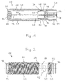
- FIG. 1 is a longitudinal section along the line 1 - 1 in FIG. 3 ,
- the connector 40 is connected to the housing sleeve 20 at a terminal end 24 in a manner described in more detail below.
- a sensor element 60 is arranged at a measuring end 22 opposite the connection end 22 of the housing sleeve 20 at a measuring end 22 opposite the connection end 22 of the housing sleeve 20, a sensor element 60 is arranged.
- the electronic sensor is an inductive sensor and, accordingly, the sensor element 60 is a sensor coil in a coil former.
- the inner lining 30 forms In the region of the measuring end 22 in the illustrated embodiment, a receptacle for the sensor element 60, so that a separate cup for the sensor element is not required here.
- an electronic assembly 70 with a circuit board 72 is present in the interior 28 of the housing sleeve 20 according to the invention.
- the printed circuit board 70 is held at the measuring end 22 by the sensor element 60 and at the connection end 24 by a receptacle formed in the connection body 50.
- the circuit board 72 carries components of a sensor electronics, which are not shown in detail. In the region of the connection end 24, the printed circuit board 72 projects into a receptacle formed in the connection body 50.
- LEDs 74 There are arranged on an upper and a lower side LEDs 74 on the circuit board 72, which are used to display optical status and / or measurement information.
- the housing sleeve 20 and the connecting sleeve 42 are made of metal and have a tubular or circular cylindrical shape. On its outer side, the housing sleeve 20 is provided with a thread 26, so that the sensor 10 can be screwed into a holder and optionally adjusted there.
- the connecting piece 40 is formed in the embodiment shown as a connector. That is, the ferrule 42, which may also be referred to as a lid, and the terminal body 50, which may also be referred to as a plastic inner liner, are configured to constitute the housing parts of a connector. In order to fix a connection cable, a thread 44 is also provided on an outer side of the connection sleeve 42.
- the inner lining 30 is closed on one side in the region of the measuring end of the housing sleeve 20, that is to say of the base housing, so that a lid-like closure 32 is formed there by the inner lining 30.
- a lid-like closure 32 is formed there by the inner lining 30.
- the sensor element 60 On the inside of this conclusion 32 is as out Fig. 1 can be seen, the sensor element 60 at.
- the termination 32 prevents vapors or other impurities from penetrating into the interior 28 of the sensor from the measuring end 22. This represents a significant advantage compared to the prior art.
- the connecting piece 40 is attached to the connecting end 24 of the housing sleeve 20 such that the connecting piece 40 seals with the inner lining 30.
- any housing assembly constitutes a potential weak point and is therefore unfavorable in principle from the viewpoint of as dense encapsulation as possible.
- the essential inventive approach is therefore to reduce the number of joints from the outset to a minimum.
- the connecting body 50 is also introduced into the connecting sleeve 42 by injection molding.
- the connection body 50 consists of a light-conducting plastic, so that optical information from the light-emitting diodes 74 can be conducted to the outside.
- a plurality of openings 49 are present in the connecting sleeve 42.
- the connecting sleeve 42 is formed so that the connecting body 50, the recesses 49 fills and forms transparent windows in this way.
- the connecting body 50 protrudes beyond the connecting sleeve 42 and forms an overhang 56. If openings are formed in a union nut to be screwed on, optical information can also be read there by a user because of the light-conducting properties of the connecting body 50.
- the housing sleeve 20 and the connecting sleeve 42 abut one another in a region 46 and are connected to one another in an undetachable manner after assembly, preferably welded. This can be done in particular by laser welding, whereby the heating caused by the welding is locally limited as far as possible and therefore the seal is not affected altogether.
- a circumferential weld seam 90 is formed during manufacture, so that as a result the seal as a whole can be further improved.
- a pre-fixing of the connecting sleeve 42 with respect to the housing sleeve 20 is achieved by a formed on the connecting sleeve 42 shoulder 48 with reduced outer diameter, which projects into the housing sleeve 20 and is guided by this.
- a sealing ring 80 is provided to provide the best possible seal between the housing sleeve 20 and the connector 40.
- a defined positioning of this Sealing ring 80 is made possible by a tubular extension 52 of the connecting body 50. How out Fig.
- the sealing ring 80 is pushed onto the pipe socket 52 prior to assembly and then the connector 40 is attached to the sealing ring 80 to the terminal end 24 of the housing sleeve 20 and the connecting sleeve 42 is welded to the housing sleeve 20.
- the housing sleeve 20 and the associated connector 40 are therefore designed so that they partially overlap and overlap in the assembled state and are sealed by a smallest possible number of seals, preferably by only a single functional seal, which is arranged in the region of the cover ,
- a defined receiving space for the sealing ring 80 is provided by a region 34 formed at the connection-side end of the inner lining 30 with reduced wall thickness. So that a coupling can be plugged with correct polarity onto the contact pins 76, a coding rib 58 is also provided on the inside of the connection body, which engages with a correspondingly shaped groove in a coupling element.
- Both the inner lining 30 and the connecting body 50 may be formed of an elastomeric material.
- FIGS. 5 and 6 a second embodiment of the sensor 10 according to the invention is shown.
- the connector 40 is designed as a cable outlet for the cable 78.
- a sealing lip 54 is formed on the connecting body 50 in the region in which it protrudes beyond the connecting sleeve 42.
- connection body 50 is slightly different from the connection body 50 of the first embodiment of FIGS. 1 to 4 educated. It has in its rear region a circumferential sealing device 53, which is provided with the cable sheath of the cable 78 for sealing the interior 28 of the sensor.
- the cable 78 is continued with its electrical lines except for the electrical assembly 70, in particular the printed circuit board 72, where it is connected to the existing components.
- a two-part strain relief 45 is additionally provided. This is mounted around the cable 78 and then inserted into the fitting 40. Here it comes to lie in the connection body 50, which in turn is designed to hold the strain relief 45 safely.
- the LEDs 74 are below the strain relief 45, so that it is also designed to be light-conducting, for example transparent, in order to forward the light signals of the LEDs 74 to the outside.
- a support ring 62 is provided, which is positioned in the assembled state in the contact region of the housing sleeve 20 with the connector 40.
- the support ring 62 supports on the one hand the sealing lip 54 so that it forms a sealing connection with the engagement portion 36, on the other hand, it also serves for a safer placement of the electronic assembly 70th
- a novel electronic sensor in which particularly good sealing properties are achieved by a reduced number of housing assemblies.
- the sensors according to the invention can be used particularly advantageously in areas where a high level of contamination is to be expected, for example in the food processing industry.
Landscapes
- Physics & Mathematics (AREA)
- General Physics & Mathematics (AREA)
- Connector Housings Or Holding Contact Members (AREA)
- Measuring Fluid Pressure (AREA)
- Investigating Or Analyzing Materials By The Use Of Electric Means (AREA)
- Casings For Electric Apparatus (AREA)
Abstract
Description
- Die vorliegende Erfindung bezieht sich in einem ersten Gesichtspunkt auf einen elektronischen Sensor nach dem Oberbegriff des Anspruchs 1.
- In einem weiteren Aspekt betrifft die Erfindung ein Verfahren zur Herstellung eines Sensors.
- Ein gattungsgemäßer elektronischer Sensor ist beispielsweise in
DE 102 37 904 B4 offenbart und weist folgende Komponenten auf: Eine Gehäusehülse, ein Sensorelement zum Messen einer physikalischen Messgröße, welches an einem Messende der Gehäusehülse angeordnet ist, eine in der Gehäusehülse angeordnete elektronische Baugruppe und ein Anschlussstück, welches an einem dem Messende gegenüberliegenden Anschlussende der Gehäusehülse angeordnet ist. - Derartige Sensoren werden bei einer großen Vielzahl von Einsatzbereichen im industriellen Bereich verwendet.
- Elektronisch arbeitende Sensoren sind in der Regel so aufgebaut, dass mindestens eine elektronische oder elektromechanische Baugruppe in einem Gehäuse montiert ist, das seinerseits wieder aus mehreren Teilen besteht, um eine kostengünstige Montage der Funktionskomponente aus mehreren Richtungen zu ermöglichen. Das hat den Nachteil, dass die Gehäuseteile während der Fertigung miteinander verbunden und alle Gehäuseöffnungen nach der Montage verschlossen werden müssen. Das ist insbesondere dann unvorteilhaft, wenn die Sensoren in sogenannten Feuchtapplikationen eingesetzt werden sollen, in denen an die Dichtigkeit der Gehäusezusammenfügungen besonders hohe Ansprüche gestellt werden.
- In
DE 100 13 218 A1 wird vorgeschlagen, die Gehäusehülse eines gattungsgemäßen Sensors, in welche das Sensorelement, die elektronische Baugruppe und das Anschlussstück eingesetzt sind, zumindest teilweise mit einer Formmasse zu verfüllen, um die Elektronik vor Feuchtigkeitseinwirkungen zu schützen. - Aufgabe der Erfindung ist es, einen elektronischen Sensor der oben genannten Art bereitzustellen, der einfach herzustellen ist und bei dem verbesserte Dichtigkeitseigenschaften erreicht werden. Außerdem soll ein Verfahren zur Herstellung eines Sensors mit den genannten Eigenschaften angegeben werden.
- Diese Aufgabe wird in einem ersten Aspekt durch den elektronischen Sensor mit den Merkmalen des Anspruchs 1 und in verfahrensmäßiger Hinsicht durch das Verfahren mit den Merkmalen des Anspruchs 18 gelöst.
- Bevorzugte Ausführungsbeispiele des erfindungsgemäßen elektronischen Sensors und vorteilhafte Varianten des erfindungsgemäßen Verfahrens sind Gegenstand der abhängigen Ansprüche.
- Ein elektronischer Sensor der oben angegebenen Art ist erfindungsgemäß dadurch weitergebildet, dass die Gehäusehülse mit einer Innenauskleidung aus Kunststoff versehen ist, welche am Messende der Gehäusehülse geschlossen ist, und dass die Innenauskleidung bis zum Anschlussende der Gehäusehülse soweit durchreicht, dass sich das Anschlussstück mit der Innenauskleidung in einem dichtungsmäßigen Eingriff befindet.
- Bei dem erfindungsgemäßen Verfahren zur Herstellung eines Sensors wird eine Gehäusehülse mit einer Innenauskleidung versehen, wobei die Innenauskleidung an einem Messende der Gehäusehülse geschlossen ist und bis zu einem dem Messende gegenüberliegenden Anschlussende der Gehäusehülse durchreicht. Weiterhin wird ein Sensorelement zum Messen einer physikalischen Messgröße und eine elektronische Baugruppe in die Gehäusehülse eingeführt, ein Anschlussstück wird an das Anschlussende der Gehäusehülse angesetzt und eine Verbindung wird zwischen dem Anschlussstück und dem Anschlussende der Gehäusehülse so hergestellt, dass das Anschlussstück mit der Innenauskleidung in einen dichtenden Eingriff kommt.
- Als Kerngedanke der Erfindung kann angesehen werden, einen elektronischen Sensor so aufzubauen, dass die Zahl der abzudichtenden Übergänge im Vergleich zum Stand der Technik reduziert wird. Insbesondere wird erfindungsgemäß ein elektronischer Sensor vorgeschlagen, bei dem im Wesentlichen nur ein abzudichtender Übergang vorhanden ist.
- Ein weiterer Kerngedanke der Erfindung besteht in diesem Zusammenhang darin, die Zahl der zu verbindenden Komponenten möglichst gering zu halten, so dass der Herstellungsaufwand auch in dieser Hinsicht reduziert werden kann.
- Ein wesentlicher Vorteil der Erfindung kann darin gesehen werden, dass wegen der im Vergleich zum Stand der Technik reduzierten Zahl von abzudichtenden Übergängen deutlich verbesserte Dichtigkeitseigenschaften erzielt werden. Der erfindungsgemäße Sensor ist deshalb besonders vorteilhaft für Anwendungen im Hygienebereich, beispielsweise in der lebensmittelverarbeitenden Industrie.
- Eine erhebliche Verbesserung im Vergleich zum Stand der Technik wird durch das Merkmal erreicht, dass die Innenauskleidung der Gehäusehülse am Messende geschlossen ist, so dass vom Messende keine Dämpfe oder sonstigen Verunreinigungen in das Innere des Sensors eindringen können.
- Im Wesentlichen besteht das Sensorgehäuse demnach aus zwei Teilen, die beim Zusammenbau zusammengefügt werden müssen, nämlich die Gehäusehülse mit der Innenauskleidung sowie das Anschlussstück, welches mit der Gehäusehülse zu verbinden ist. Die Gehäusehülse mit der Innenauskleidung kann auch als Basisgehäuse und das Anschlussstück kann auch als Deckel bezeichnet und angesehen werden.
- Die Erfindung kann grundsätzlich für alle Arten von Sensoren, beispielsweise induktive, kapazitive, optische, Ultraschall- oder Temperatursensoren, verwendet werden. Besonders vorteilhaft kann die Erfindung aber für Sensoren eingesetzt werden, bei denen die am Messende geschlossene Innenauskleidung keine weiteren konstruktiven Aufgabenstellungen mit sich bringt. Dies ist insbesondere bei induktiven Sensoren der Fall.
- Prinzipiell können das Basisgehäuse und der ihm zugeordnete Deckel beliebige Formen haben. Besonders bevorzugt weist aber die Gehäusehülse eine im Wesentlichen zylindrische Form auf. Hierbei kann es sich wiederum grundsätzlich um Zylinder mit beliebiger Grundfläche handeln. Zweckmäßigerweise weist jedoch die Gehäusehülse eine Zylinderkreisform auf, wobei insbesondere auf der Außenseite der Gehäusehülse ein Gewinde zum Befestigen und gegebenenfalls zum Justieren des Sensors in einer Halterung vorhanden ist. Im Wesentlichen weist das Gehäuse also eine Zylinder- oder Rohrform auf.
- Prinzipiell kann die Gehäusehülse aus einem beliebigen Material, beispielsweise auch aus Kunststoff, gefertigt sein. Bei bevorzugten Varianten sind jedoch das Basisgehäuse, also die Gehäusehülse, und mindestens Teile des Deckels, aus Metall gebildet, wobei diese Komponenten auf ihren Innenseiten vollständig oder nur teilweise mit Kunststoff ausgekleidet sein können.
- Damit ein Durchtritt von Gasen, insbesondere von Wasserdampf, durch die Innenverkleidung möglichst weitgehend reduziert wird, ist die Innenauskleidung bevorzugt aus einem Material mit geringer Dampfdiffusionsrate gebildet. Besonders vorteilhaft können für die Innenauskleidung Materialien verwendet werden, bei denen die Dampfdiffusionsraten um etwa einen Faktor 10 bis 100, also um ein bis zwei Größenordnungen, unter den Werten von standardmäßig eingesetzten Materialien, wie beispielsweise Polyamiden, liegen.
- Beispielsweise können für die Innenauskleidung LCP-Materialien (Liquid Crystal Polymere) verwendet werden, die sich durch besonders niedrige Dampfdiffusionsraten, insbesondere niedrige Wasserdampftransmissionsraten und niedrigen Sauerstoff-Permeabilitäten, auszeichnen.
- Besonders zweckmäßig werden Materialien eingesetzt, bei denen die Wasserdampftransmissionsrate kleiner ist als 0,1 g x mm/ m2 x Tag, besonders bevorzugt kleiner als 0,01 g x mm/ m2 x Tag, und/oder bei denen die Sauerstoff-Permeabilität kleiner ist als 0,1 cm3 x mm/m2 x Tag x atm, besonders bevorzugt kleiner als 0,01 cm3 x mm/m2 x Tag x atm.
- Besonders vorteilhaft kann der erfindungsgemäße Sensor für hygienisch anspruchsvolle Anwendungen, z.B. in der Lebensmitteltechnik, eingesetzt werden.
- Bei einer weiteren vorteilhaften Ausgestaltung weist das Anschlussstück eine mit der Gehäusehülse zu verbindende Anschlusshülse und einen Anschlusskörper aus Kunststoff auf. Die Anschlusshülse ist dabei zweckmäßig aus Metall gefertigt. Der Anschlusskörper kann auch als Innenauskleidung der Anschlusshülse bezeichnet und angesehen werden. Bei dieser Ausgestaltung der Erfindung sind dann beim Zusammenbau des Sensors im Wesentlichen nur zwei Metallteile, nämlich die Gehäusehülse und die Anschlusshülse, miteinander zu verbinden, so dass vereinfacht betrachtet das Sensorgehäuse im Wesentlichen aus zwei Teilen, nämlich dem Basisgehäuse und dem Deckel, besteht.
- Im Prinzip kann auch ergänzend oder alternativ eine Verbindung zwischen dem Anschlusskörper und der Gehäusehülse und/oder der Innenauskleidung vorgesehen sein. Wichtig ist gemäß der Erfindung, dass das Anschlussstück in irgendeiner Weise mit der becherartigen Innenauskleidung der Gehäusehülse abdichtet.
- Grundsätzlich kann das Anschlussstück als oder mit einem Kabelabgang oder als oder mit einem Steckverbinder gebildet sein. Für die Ausführungsvariante als Kabelabgang muss für eine Abdichtung zwischen dem Kabel und dem Anschlusskörper gesorgt werden.
- Eine Möglichkeit zur Abdichtung des Kabelausganges ist, am Anschlusskörper Dichteinrichtungen zum abgedichteten Ausführen des Kabels vorzusehen. Diese können direkt einstückig als Teile des Anschlusskörpers ausgebildet sein.
- Um eine sichere Befestigung des Kabels innerhalb des Sensors zu erreichen, ist bevorzugt vorgesehen, dass im Anschlusskörper zugentlastende Elemente vorhanden sind. Diese können beispielsweise in Form einer zweiteiligen Hülse ausgeführt sein, die um das Kabel gelegt wird und in den Anschlusskörper eingesetzt wird. In diesem Zusammenhang ist es bevorzugt, wenn sowohl die Dichteinrichtungen wie auch die zugentlastenden Elemente derart ausgebildet sind, dass sich die Dichtwirkung wie auch die Zugentlastung durch Zugkräfte auf das Kabel verstärken.
- Die Funktionalität des Sensorgehäuses insgesamt wird erhöht, wenn die Anschlusshülse Ausnehmungen aufweist zum Bilden von Fenstern für optische Informationen aus dem Sensorinneren. Hierbei kann es sich beispielsweise um Status- oder Messinformationen handeln, z.B. "Objekt erkannt" oder "Selbsttest läuft", welche insbesondere über Leuchtdioden, die Teil der elektronischen Baugruppe sein können, abgegeben werden.
- Prinzipiell kann die Innenauskleidung ein separates Bauteil sein, welches in die Gehäusehülse hineingesteckt wird. Besonders bevorzugt wird aber die Innenauskleidung in die Gehäusehülse durch Spritzguss eingebracht. Hierdurch wird bereits eine besonders innige Verbindung zwischen der Gehäusehülse und der Innenauskleidung erreicht.
- Bei bevorzugten Ausführungsvarianten wird auch der Anschlusskörper in die Anschlusshülse eingespritzt. Dieses Verfahren kann in entsprechender Weise wie das Anbringen der Innenauskleidung in der Gehäusehülse erfolgen.
- Bei der Auslegung des Anschlusskörpers ist bevorzugt vorgesehen, dass der Anschlusskörper mit den Ausnehmungen im Anschlussstück eine im wesentlichen lückenlose Verbindung eingeht, damit keine Schmutzkanten oder Keimnester entstehen können. Dies kann besonders einfach bei einem Einbringen des Anschlussstücks durch Spritzgussverfahren erreicht werden.
- Um ein Herausleiten von optischen Informationen zu ermöglichen, wird der Anschlusskörper zweckmäßig aus einem lichtleitenden Kunststoff gebildet. Auch die Innenauskleidung der Gehäusehülse kann aus einem transparenten oder lichtleitenden Material gebildet sein. Es können dann optische Informationen auch über die Innenauskleidung, beispielsweise an das Messende und/oder an das Anschlussende geleitet werden.
- Das Verbinden der Gehäusehülse mit der Anschlusshülse kann prinzipiell auf beliebige Weise erfolgen. Beispielsweise kann die Anschlusshülse mit der Gehäusehülse verschweißt werden. Bei einfachen Ausführungen können hierzu nur einige wenige Schweißpunkte angebracht werden. Die Dichtigkeit insgesamt kann aber noch weiter erhöht werden, wenn zwischen der Gehäusehülse und der Anschlusshülse eine umlaufende Schweißnaht gebildet ist, welche beispielsweise mittels Laserschweißen erzeugt werden kann.
- In mechanischer Hinsicht kann weiterhin bevorzugt sein, wenn die Gehäusehülse und die Anschlusshülse einander überlappen. Einerseits wird dadurch ein Verschweißen erleichtert und andererseits können die Ränder der Gehäuse- und der Anschlusshülse auch so geformt sein, dass die Anschlusshülse beim Zusammenbau des Sensors mit der Gehäusehülse verrastet werden kann. Eine solche Verrastung kann insbesondere für eine erste Fixierung sinnvoll sein, da hierdurch wiederum das Anbringen einer Schweißnaht erleichtert wird.
- Die Funktionalität der Innenauskleidung wird erhöht, wenn durch die Innenauskleidung im Bereich des Messendes eine Aufnahme für das Sensorelement gebildet ist. Zweckmäßig wird hierzu ein Innendurchmesser der Innenauskleidung so gewählt, dass ein beispielsweise zylindrisches Sensorelement leicht in die Innenauskleidung eingeschoben werden kann und von dieser geführt und gehalten ist. Ein separater Becher ist dann nicht mehr notwendig.
- Das Herausleiten von optischen Informationen kann effektiver erfolgen, wenn eine Leiterplatte der elektronischen Baugruppe in einem Bereich, in dem LEDs angeordnet sind, in den transparenten Anschlusskörper hineinragt.
- Beim optionalen Vorsehen von Elementen für die Zugentlastung ist es zweckmäßig, diese ebenfalls transparent auszulegen, um ein gutes Weiterleiten der von den LED ausgesendeten Lichtsignale zu ermöglichen.
- Um die Dichtung zwischen den beiden Teilen, also zwischen der Gehäusehülse mit der Innenauskleidung und dem Anschlussstück, zu verbessern, ist zweckmäßig ein Dichtring zwischen der Innenauskleidung und dem Anschlussstück vorhanden. Hierzu kann bevorzugt der Anschlusskörper einen in das Innere der Innenauskleidung hineinragenden Rohransatz aufweisen, dessen Außenseite eine Anlagefläche für den Dichtring bildet. Ein definierter Sitz der Dichtung wird dadurch erleichtert.
- Eine weitere Verbesserung der Dichteigenschaften kann in diesem Zusammenhang dadurch erreicht werden, dass ein Innenbereich der Innenauskleidung der Gehäusehülse mit dem Rohransatz in einem Dichtungsbereich überlappt und dass die Innenauskleidung im Dichtungsbereich zum Bilden eines Aufnahmeraums für einen Dichtring eine reduzierte Dicke aufweist. Es können so hervorragende Dichtigkeitseigenschaften erzielt werden.
- Eine Alternative oder ergänzende Möglichkeit zum Ausbilden einer Verbesserung der Dichteigenschaften ist es, wenn der Anschlusskörper eine Dichtlippe ausbildet, und an der Innenauskleidung der Gehäusehülse ein mit der Dichtlippe zusammenwirkender Eingriffsbereich vorgesehen ist. Hierbei ist es möglich, die Dichtlippe derart auszubilden, dass, wenn die Anschlusshülse in die Gehäusehülse eingeführt wird, die Dichtlippe leicht in den Innenraum zurückgedrückt wird und im Eingriffsbereich der Innenauskleidung wieder in die ursprüngliche Position zurückgleiten kann. Bei einer derartigen Konstruktion kann die Dichtlippe mit dem Eingriffsbereich zusätzlich als Rasteinrichtung vorgesehen werden, die ein Platzieren der Anschlusshülse in der Gehäusehülse erleichtert und eine zwischenzeitliche Fixierung vor dem Zusammenschweißen der beiden Hülsen ermöglicht.
- In einer weiteren Ausführungsform kann zusätzlich als Fortsetzung des Anschlusskörpers in Richtung des Messendes in die Innenauskleidung ein Stützring angebracht werden. Dieser kann zum zusätzlichen Halten und Fixieren der im Sensor vorgesehenen elektronischen Bauelemente dienen.
- Weitere Vorteile und Merkmale des erfindungsgemäßen elektronischen Sensors und des erfindungsgemäßen Herstellungsverfahrens werden nachstehend mit Bezug auf die schematischen Figuren erläutert.
- Hierin zeigen:
- Fig. 1
- Eine Längsschnittansicht eines ersten Ausführungsbeispiels eines erfin- dungsgemäßen elektronischen Sensors;
- Fig. 2
- eine Seitenansicht des elektronischen Sensors aus
Fig. 1 ; - Fig. 3
- eine Querschnittsansicht des Sensors aus
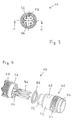
Fig. 1 ; - Fig. 4
- in perspektivischer Teilansicht eine Explosionsdarstellung des An- schlussendes des Sensors aus
Fig. 1 ; - Fig. 5
- eine Längsschnittansicht eines zweiten Ausführungsbeispiels eines erfin- dungsgemäßen elektronischen Sensors; und
- Fig. 6
- eine Explosionsdarstellung des elektronischen Sensors aus
Figur 5 . - Das in den
Figuren 1 bis 4 gezeigte erste Ausführungsbeispiel eines erfindungsgemäßen elektronischen Sensors 10 weist als wesentliche Bestandteile eine Gehäusehülse 20 mit einer durch Spritzguss eingebrachten Innenauskleidung 30 sowie ein Anschlussstück 40 mit einer Anschlusshülse 42 und einem Anschlusskörper 50 auf. Die Komponenten sind in den Figuren jeweils mit denselben Bezugszeichen versehen.Figur 1 ist ein Längsschnitt entlang der Linie 1 - 1 inFigur 3 . - Das Anschlussstück 40 ist mit der Gehäusehülse 20 an einem Anschlussende 24 in einer im Folgenden näher beschriebenen Weise verbunden. An einem dem Anschlussende 24 gegenüberliegenden Messende 22 der Gehäusehülse 20 ist ein Sensorelement 60 angeordnet. Im gezeigten Ausführungsbeispiel ist der elektronische Sensor ein induktiver Sensor und dementsprechend handelt es sich bei dem Sensorelement 60 um eine Sensorspule in einem Spulenkörper. Die Innenauskleidung 30 bildet im Bereich des Messendes 22 im dargestellten Ausführungsbeispiel eine Aufnahme für das Sensorelement 60, so dass ein separater Becher für das Sensorelement hier nicht erforderlich ist. Im Inneren 28 der Gehäusehülse 20 ist erfindungsgemäß eine elektronische Baugruppe 70 mit einer Leiterplatte 72 vorhanden. Die Leiterplatte 70 wird am Messende 22 durch das Sensorelement 60 und am Anschlussende 24 durch eine im Anschlusskörper 50 gebildete Aufnahme gehalten. Die Leiterplatte 72 trägt Komponenten einer Sensorelektronik, die nicht im Detail dargestellt sind. Im Bereich des Anschlussendes 24 ragt die Leiterplatte 72 in eine im Anschlusskörper 50 gebildete Aufnahme hinein. Dort sind an einer Ober- und einer Unterseite Leuchtdioden 74 auf der Leiterplatte 72 angeordnet, die zum Anzeigen von optischen Status- und/oder Messinformationen dienen. Die Gehäusehülse 20 und die Anschlusshülse 42 bestehen aus Metall und weisen eine Röhren- oder Kreiszylinderform auf. Auf ihrer Außenseite ist die Gehäusehülse 20 mit einem Gewinde 26 versehen, damit der Sensor 10 in eine Halterung eingeschraubt und dort gegebenenfalls justiert werden kann.
- Das Anschlussstück 40 ist im gezeigten Ausführungsbeispiel als Steckverbinder gebildet. Das heißt, dass die Anschlusshülse 42, die auch als Deckel bezeichnet werden kann, und der Anschlusskörper 50, der auch als Kunststoffinnenauskleidung bezeichnet werden kann, so gestaltet sind, dass sie die Gehäuseteile eines Steckverbinders darstellen. Um ein Anschlusskabel befestigen zu können, ist an einer Außenseite der Anschlusshülse 42 ebenfalls ein Gewinde 44 vorhanden.
- Gemäß einem wesentlichen Gedanken der Erfindung ist die Innenauskleidung 30 im Bereich des Messendes der Gehäusehülse 20, also des Basisgehäuses, einseitig geschlossen, so dass dort durch die Innenauskleidung 30 ein deckelartiger Abschluss 32 gebildet ist. An der Innenseite dieses Abschlusses 32 liegt, wie aus
Fig. 1 ersichtlich, das Sensorelement 60 an. Durch den Abschluss 32 wird verhindert, dass vom Messende 22 Dämpfe oder sonstige Verunreinigungen in das Innere 28 des Sensors eindringen können. Dies stellt einen erheblichen Vorteil im Vergleich zum Stand der Technik dar. - Gemäß einem weiteren wesentlichen Gedanken der Erfindung ist das Anschlussstück 40 so am Anschlussende 24 der Gehäusehülse 20 angebracht, dass das Anschlussstück 40 mit der Innenauskleidung 30 dichtend abschließt. Auf diese Weise wird ein wesentliches Ziel der Erfindung, nämlich die Anzahl der Gehäusezusammenfügungen und demgemäß die Anzahl der abzudichtenden Übergänge, zu minimieren, erreicht.
- Mit der erfindungsgemäßen Konstruktion wird demnach nicht versucht, die Qualität der Gehäusezusammenfügungen als solcher zu verbessern. Erfindungsgemäß wurde erkannt, dass grundsätzlich jede Gehäusezusammenfügung eine potentielle Schwachstelle darstellt und deshalb unter dem Gesichtspunkt einer möglichst dichten Kapselung prinzipiell ungünstig ist. Der wesentliche erfindungsgemäße Ansatz besteht deshalb darin, die Anzahl der Zusammenfügungen von vornherein auf ein Minimum zu reduzieren.
- Wie die Innenauskleidung 30 in die Gehäusehülse 20, ist auch der Anschlusskörper 50 in die Anschlusshülse 42 durch Spritzguss eingebracht. Der Anschlusskörper 50 besteht aus einem lichtleitenden Kunststoff, damit optische Informationen von den Leuchtdioden 74 nach außen geleitet werden können. Hierzu sind in der Anschlusshülse 42 eine Mehrzahl von Öffnungen 49 vorhanden. Im gezeigten Ausführungsbeispiel ist die Anschlusshülse 42 so gebildet, dass der Anschlusskörper 50 die Ausnehmungen 49 ausfüllt und auf diese Weise transparente Fenster bildet.
- An einem vorderen Ende des Anschlussstücks 40 steht der Anschlusskörper 50 über die Anschlusshülse 42 vor und bildet eine Überkragung 56. Wenn in einer aufzuschraubenden Überwurfmutter Öffnungen gebildet sind, können dort wegen der lichtleitenden Eigenschaften des Anschlusskörpers 50 ebenfalls optische Informationen von einem Benutzer abgelesen werden.
- Die Gehäusehülse 20 und die Anschlusshülse 42 stoßen in einem Bereich 46 aneinander und werden dort nach der Montage miteinander unlösbar verbunden, vorzugsweise verschweißt. Dies kann insbesondere durch Laserschweißen erfolgen, wodurch die durch das Schweißen bedingte Erwärmung lokal weitestgehend begrenzt ist und deshalb die Dichtung insgesamt nicht beeinträchtigt wird.
- Im gezeigten Beispiel wird bei der Fertigung eine umlaufende Schweißnaht 90 gebildet, so dass hierdurch die Abdichtung insgesamt weiter verbessert werden kann.
- Eine Vorfixierung der Anschlusshülse 42 bezüglich der Gehäusehülse 20 wird durch einen an der Anschlusshülse 42 gebildeten Ansatz 48 mit reduziertem Außendurchmesser, der in die Gehäusehülse 20 hineinragt und von dieser geführt wird, erzielt. Zum Bereitstellen einer möglichst guten Abdichtung zwischen der Gehäusehülse 20 und dem Anschlussstück 40 ist ein Dichtring 80 vorgesehen. Eine definierte Positionierung dieses Dichtrings 80 wird durch einen Rohransatz 52 des Anschlusskörpers 50 ermöglicht. Wie aus
Fig. 4 ersichtlich, wird der Dichtring 80 vor der Montage auf den Rohransatz 52 aufgeschoben und anschließend wird das Anschlussstück 40 mit dem Dichtring 80 an das Anschlussende 24 der Gehäusehülse 20 angesetzt und die Anschlusshülse 42 wird mit der Gehäusehülse 20 verschweißt. Die Gehäusehülse 20 und das zugeordnet Anschlussstück 40 sind demnach so gestaltet, dass sie sich im montierten Zustand teilweise überdecken und überlappen und durch eine kleinstmögliche Anzahl von Dichtungen, vorzugsweise durch nur eine einzige funktionsmäßige Dichtung, die im Bereich der Überdeckung angeordnet ist, dicht verschlossen sind. - Wie aus
Fig. 1 ersichtlich, wird ein definierter Aufnahmeraum für den Dichtring 80 bereitgestellt durch einen am anschlussseitigen Ende der Innenauskleidung 30 gebildeten Bereich 34 mit reduzierter Wandstärke. Damit eine Kupplung polrichtig auf die Kontaktstifte 76 aufgesteckt werden kann, ist außerdem an der Innenseite des Anschlusskörpers eine Kodierrippe 58 vorgesehen, welche mit einer entsprechend geformten Nut in einem Kupplungselement in Eingriff kommt. - Sowohl die Innenauskleidung 30 wie auch der Anschlusskörper 50 können aus einem elastomeren Werkstoff ausgebildet sein.
- In den
Figuren 5 und 6 ist ein zweites Ausführungsbeispiel des erfindungsgemäßen Sensors 10 gezeigt. In dieser Ausführungsform ist das Anschlussstück 40 als Kabelabgang für das Kabel 78 ausgelegt. - Im Folgenden wird lediglich auf die Unterschiede zwischen dieser Ausführungsform und der Ausführungsform der
Figuren 1 bis 4 eingegangen. Hierbei sind gleiche Komponenten jeweils mit denselben Bezugszeichen versehen. - Zusätzlich ist in diesen Figuren eine Ausführungsform dargestellt, die ohne einen zusätzlichen Dichtring 80 eine ausreichende Dichtwirkung erzielt.
- Zu diesem Zweck ist am Anschlusskörper 50 in dem Bereich, in dem er über die Anschlusshülse 42 hinaussteht, eine Dichtlippe 54 ausgebildet. Beim Zusammensetzen des Sensors 10, wobei das Anschlussstück 40 auf bzw. in die Gehäusehülse 20 geschoben wird, wird auch der Bereich des Anschlusskörpers 50, an dem die Dichtlippe 54 ausgebildet ist, in die Gehäusehülse 20 hineingeschoben. In der Innenauskleidung 30 der Gehäusehülse 20 ist wiederum ein Eingriffsbereich 36 für die Dichtlippe 54 ausgebildet, in den die Dichtlippe 54 eingreift.
- Der Anschlusskörper 50 ist in der hier gezeigten Ausführungsform etwas unterschiedlich zu dem Anschlusskörper 50 der ersten Ausführungsform der
Figuren 1 bis 4 ausgebildet. Er weist in seinem hinteren Bereich eine umlaufende Dichteinrichtung 53 auf, die mit dem Kabelmantel des Kabels 78 zum Abdichten des Innenraums 28 des Sensors vorgesehen ist. - Das Kabel 78 ist mit seinen elektrischen Leitungen bis auf die elektrische Baugruppe 70, insbesondere die Leiterplatte 72, weitergeführt und dort mit den vorhandenen Bauteilen verbunden. Um diese Verbindung von Zug zu entlasten, ist zusätzlich eine zweiteilige Zugentlastung 45 vorgesehen. Diese wird um das Kabel 78 angebracht und anschließend in das Anschlussstück 40 eingeführt. Hierbei kommt sie im Anschlusskörper 50 zu liegen, welcher wiederum ausgebildet ist, um die Zugentlastung 45 sicher zu halten. Wie in
Figur 5 dargestellt, befinden sich die LEDs 74 unterhalb der Zugentlastung 45, so dass diese auch lichtleitend, beispielsweise transparent ausgeführt ist, um die Lichtsignale der LEDs 74 nach außen weiter zu leiten. - Um eine weitere Fixierung des Kabels 78 und der elektrischen Baugruppe 70 zu erleichtern, ist ein Stützring 62 vorgesehen, welcher in zusammengebautem Zustand im Kontaktbereich der Gehäusehülse 20 mit dem Anschlussstück 40 positioniert ist. Der Stützring 62 stützt zum einen die Dichtlippe 54, damit sie eine abdichtende Verbindung mit dem Eingriffsbereich 36 ausbildet, zum anderen dient sie auch zu einer sichereren Platzierung der elektronischen Baugruppe 70.
- Mit der vorliegenden Erfindung wird ein neuartiger elektronischer Sensor bereitgestellt, bei dem durch eine reduzierte Anzahl von Gehäusezusammenfügungen besonders gute Eigenschaften im Hinblick auf die Dichtigkeit erreicht werden. Die erfindungsgemäßen Sensoren sind besonders vorteilhaft einsetzbar in Bereichen, bei denen mit einem hohen Eintrag von Verunreinigungen zu rechnen ist, beispielsweise in der lebensmittelverarbeitenden Industrie.
Claims (20)
- Elektronischer Sensor, insbesondere induktiver Sensor,
mit einer Gehäusehülse (20),
mit einem Sensorelement (60) zum Messen einer physikalischen Messgröße, welches an einem Messende (22) der Gehäusehülse (20) angeordnet ist, mit einer in der Gehäusehülse (20) angeordneten elektronischen Baugruppe (70),
und mit einem Anschlussstück (40), welches an einem dem Messende (22) gegenüberliegenden Anschlussende (24) der Gehäusehülse (20) angeordnet ist,
dadurch gekennzeichnet,
dass die Gehäusehülse (20) mit einer Innenauskleidung (30) aus Kunststoff versehen ist, welche am Messende (22) der Gehäusehülse (20) geschlossen ist, und
dass die Innenauskleidung (30) bis zum Anschlussende (24) der Gehäusehülse (20) soweit durchreicht, dass sich das Anschlussstück (40) mit der Innenauskleidung (30) in einem dichtungsmäßigen Eingriff befindet. - Sensor nach Anspruch 1,
dadurch gekennzeichnet,
dass das Anschlussstück (40) eine insbesondere mit der Gehäusehülse (20) zu verbindende, Anschlusshülse (42) und einen Anschlusskörper (50) aus Kunststoff aufweist. - Sensor nach Anspruch 1 oder 2,
dadurch gekennzeichnet,
dass die Anschlusshülse (42) Ausnehmungen (49) aufweist zum Bilden von Fenstern für optische Informationen aus dem Inneren des Sensors. - Sensor nach einem der Ansprüche 1 bis 3,
dadurch gekennzeichnet,
dass der Anschlusskörper (50) und/oder die Innenauskleidung (30) aus einem lichtleitenden Kunststoff gebildet ist. - Sensor nach einem der Ansprüche 1 bis 4,
dadurch gekennzeichnet,
dass die Innenauskleidung (30) aus einem LCP-Material gebildet ist, welches eine Wasserdampftransmissionsrate von kleiner als 0,1 g x mm/m2 x Tag, besonders bevorzugt kleiner als 0,01 g x mm/m2 x Tag, und/oder eine Sauerstoff-Permeabilität von kleiner als 0,1 cm3 x mm/m2 x Tag x atm, besonders bevorzugt kleiner als 0,01 cm3 x mm/m2 x Tag x atm, aufweist. - Sensor nach einem der Ansprüche 1 bis 5,
dadurch gekennzeichnet,
dass der Anschlusskörper (50) in die Anschlusshülse (42) und/oder die Innenauskleidung (30) in die Gehäusehülse (20) durch Spritzguss eingebracht ist. - Sensor nach einem der Ansprüche 1 bis 6,
dadurch gekennzeichnet,
dass die Gehäusehülse (20) und die Anschlusshülse (42) einander überlappen. - Sensor nach einem der Ansprüche 1 bis 7,
dadurch gekennzeichnet,
dass durch die Innenauskleidung (30) im Bereich des Messendes (22) eine Aufnahme für das Sensorelement (60) gebildet ist. - Sensor nach einem der Ansprüche 1 bis 8,
dadurch gekennzeichnet,
dass das Anschlussstück (40) als Steckverbinder oder als Kabelabgang ausgebildet ist. - Sensor nach Anspruch 9,
dadurch gekennzeichnet,
dass am Anschlusskörper (50) Dichteinrichtungen (53) zum abgedichteten Einführen eines Kabels ausgebildet sind. - Sensor nach einem der Ansprüche 9 oder 10,
dadurch gekennzeichnet,
dass im Anschlussstück (40) zugentlastende Elemente (45) vorhanden sind. - Sensor nach einem der Ansprüche 1 bis 11,
dadurch gekennzeichnet,
dass eine Leiterplatte (72) der elektronischen Baugruppe (70) in einem Bereich, in dem LEDs angeordnet sind, in den Anschlusskörper hineinragt. - Sensor nach einem der Ansprüche 1 bis 12,
dadurch gekennzeichnet,
dass ein Dichtring (80) zwischen der Innenauskleidung (30) und dem Anschlussstück (40) vorhanden ist. - Sensor nach einem der Ansprüche 1 bis 13,
dadurch gekennzeichnet,
dass der Anschlusskörper (50) einen in das Innere (28) der Innenauskleidung (30) hineinragenden Rohransatz (52) aufweist, dessen Außenseite eine Anlagefläche für einen Dichtring (80) bildet. - Sensor nach Anspruch 14,
dadurch gekennzeichnet,
dass ein Endbereich der Innenauskleidung (30) mit dem Rohransatz (52) in einem Dichtungsbereich (34) überlappt und
dass die Innenauskleidung (30) im Dichtungsbereich (34) zum Bilden eines Aufnahmeraums für einen Dichtring (80) eine reduzierte Dicke aufweist. - Sensor nach einem der Ansprüche 1 bis 15,
dadurch gekennzeichnet,
dass am Anschlusskörper (50) eine Dichtlippe (54) ausgebildet ist und dass an der Innenauskleidung (30) ein mit der Dichtlippe (54) zusammenwirkender Eingriffsbereich (36) vorhanden ist. - Sensor nach einem der Ansprüche 1 bis 16,
dadurch gekennzeichnet,
dass als Fortsetzung des Anschlusskörpers (50) in Richtung Messende (22) in die Innenauskleidung (30) ein Stützring (62) eingebracht ist. - Verfahren zur Herstellung eines Sensors, insbesondere nach einem der Ansprüche 1 bis 17,
bei dem eine Gehäusehülse (20) mit einer Innenauskleidung (30) versehen wird, wobei die Innenauskleidung (30) an einem Messende (22) der Gehäusehülse (20) geschlossen ist und bis zu einem dem Messende (22) gegenüberliegenden Anschlussende (24) der Gehäusehülse (20) durchreicht,
bei dem ein Sensorelement (60) zum Messen einer physikalischen Messgröße und eine elektronische Baugruppe (70) in die Gehäusehülse (20) eingeführt wird, bei dem ein Anschlussstück (40) an das Anschlussende (24) der Gehäusehülse (20) angesetzt wird und
bei dem eine Verbindung zwischen dem Anschlussstück (40) und dem Anschlussende (24) der Gehäusehülse (20) so hergestellt wird, dass das Anschlussstück (40) mit der Innenauskleidung (30) in einen dichtenden Eingriff kommt. - Verfahren nach Anspruch 18,
dadurch gekennzeichnet,
dass das Anschlussstück (40) eine Anschlusshülse (42) aufweist, welche mit der Gehäusehülse (20) verbunden wird. - Verfahren nach einem der Ansprüche 18 oder 19,
dadurch gekennzeichnet,
dass die Anschlusshülse (42) mit der Gehäusehülse (20), insbesondere mit einer umlaufenden Schweißnaht (90), verschweißt wird und/oder dass die Anschlusshülse (42) beim Zusammenbau des Sensors (10) mit der Gehäusehülse (20) verrastet wird.
Priority Applications (2)
| Application Number | Priority Date | Filing Date | Title |
|---|---|---|---|
| EP08015398A EP2072967B1 (de) | 2007-09-04 | 2008-09-01 | Elektronischer Sensor und Verfahren zur Herstellung eines Sensors |
| US12/203,219 US8007170B2 (en) | 2007-09-04 | 2008-09-03 | Electronic sensor and method for the manufacture of a sensor |
Applications Claiming Priority (2)
| Application Number | Priority Date | Filing Date | Title |
|---|---|---|---|
| EP07017332A EP2034277A1 (de) | 2007-09-04 | 2007-09-04 | Elektronischer sensor und verfahren zur Herstellung eines Sensors |
| EP08015398A EP2072967B1 (de) | 2007-09-04 | 2008-09-01 | Elektronischer Sensor und Verfahren zur Herstellung eines Sensors |
Publications (2)
| Publication Number | Publication Date |
|---|---|
| EP2072967A1 true EP2072967A1 (de) | 2009-06-24 |
| EP2072967B1 EP2072967B1 (de) | 2010-03-17 |
Family
ID=39048898
Family Applications (2)
| Application Number | Title | Priority Date | Filing Date |
|---|---|---|---|
| EP07017332A Withdrawn EP2034277A1 (de) | 2007-09-04 | 2007-09-04 | Elektronischer sensor und verfahren zur Herstellung eines Sensors |
| EP08015398A Not-in-force EP2072967B1 (de) | 2007-09-04 | 2008-09-01 | Elektronischer Sensor und Verfahren zur Herstellung eines Sensors |
Family Applications Before (1)
| Application Number | Title | Priority Date | Filing Date |
|---|---|---|---|
| EP07017332A Withdrawn EP2034277A1 (de) | 2007-09-04 | 2007-09-04 | Elektronischer sensor und verfahren zur Herstellung eines Sensors |
Country Status (3)
| Country | Link |
|---|---|
| EP (2) | EP2034277A1 (de) |
| AT (1) | ATE461429T1 (de) |
| DE (1) | DE502008000450D1 (de) |
Cited By (2)
| Publication number | Priority date | Publication date | Assignee | Title |
|---|---|---|---|---|
| WO2024170375A1 (de) * | 2023-02-15 | 2024-08-22 | Pepperl + Fuchs Se | Näherungssensor |
| DE102023125206A1 (de) * | 2023-09-18 | 2025-03-20 | Ifm Electronic Gmbh | Sensor mit Zustandsanzeige |
Families Citing this family (4)
| Publication number | Priority date | Publication date | Assignee | Title |
|---|---|---|---|---|
| DE102015103551A1 (de) * | 2015-03-11 | 2016-09-15 | Sick Ag | Steckerbaugruppe für einen Sensor und Verfahren zur Montage einer Steckerbaugruppe für einen Sensor |
| DE102015119557B4 (de) * | 2015-11-12 | 2022-11-10 | Sick Ag | Sensor |
| DE102017201711A1 (de) | 2017-02-02 | 2018-08-02 | Continental Teves Ag & Co. Ohg | Sensor mit einem Schutzgehäuse |
| CN118936825B (zh) * | 2024-08-23 | 2025-03-21 | 百林机电科技(苏州)有限公司 | 一种无线适配器模组 |
Citations (2)
| Publication number | Priority date | Publication date | Assignee | Title |
|---|---|---|---|---|
| DE10013218A1 (de) | 2000-03-17 | 2001-09-27 | Balluff Gebhard Feinmech | Verfahren zur Herstellung eines Positionssensors und Positionssensor |
| DE10237904B4 (de) | 2002-06-14 | 2007-05-31 | Ifm Electronic Gmbh | Elektronischer Sensor und Baueinheit aus einem elektronischen Sensor und einem Befestigungselement |
-
2007
- 2007-09-04 EP EP07017332A patent/EP2034277A1/de not_active Withdrawn
-
2008
- 2008-09-01 EP EP08015398A patent/EP2072967B1/de not_active Not-in-force
- 2008-09-01 AT AT08015398T patent/ATE461429T1/de active
- 2008-09-01 DE DE502008000450T patent/DE502008000450D1/de active Active
Patent Citations (2)
| Publication number | Priority date | Publication date | Assignee | Title |
|---|---|---|---|---|
| DE10013218A1 (de) | 2000-03-17 | 2001-09-27 | Balluff Gebhard Feinmech | Verfahren zur Herstellung eines Positionssensors und Positionssensor |
| DE10237904B4 (de) | 2002-06-14 | 2007-05-31 | Ifm Electronic Gmbh | Elektronischer Sensor und Baueinheit aus einem elektronischen Sensor und einem Befestigungselement |
Cited By (3)
| Publication number | Priority date | Publication date | Assignee | Title |
|---|---|---|---|---|
| WO2024170375A1 (de) * | 2023-02-15 | 2024-08-22 | Pepperl + Fuchs Se | Näherungssensor |
| DE102023103618B4 (de) * | 2023-02-15 | 2025-07-31 | Pepperl+Fuchs Se | Näherungssensor mit verbesserter Schlag- und Stoßfestigkeit |
| DE102023125206A1 (de) * | 2023-09-18 | 2025-03-20 | Ifm Electronic Gmbh | Sensor mit Zustandsanzeige |
Also Published As
| Publication number | Publication date |
|---|---|
| EP2072967B1 (de) | 2010-03-17 |
| DE502008000450D1 (de) | 2010-04-29 |
| ATE461429T1 (de) | 2010-04-15 |
| EP2034277A1 (de) | 2009-03-11 |
Similar Documents
| Publication | Publication Date | Title |
|---|---|---|
| EP2339312B1 (de) | Abdichteinrichtung zum Verschliessen eines Druckmesszellengehäuses, Druckmesszelleneinrichtung bzw. Druckmessvorrichtung damit | |
| EP2072967B1 (de) | Elektronischer Sensor und Verfahren zur Herstellung eines Sensors | |
| DE19703206C2 (de) | Drucksensor-Bauteil mit Schlauchanschluß | |
| EP1989523B1 (de) | Verfahren zum herstellen einer fluiddruckmesseinheit und komponente zum einsatz in einer fluiddruckmesseinheit | |
| DE202008009002U1 (de) | Magnetfeldsensor | |
| DE102014009103B4 (de) | Drehmomentsensor-abdeckung | |
| DE112015000086T5 (de) | Raddrehzahlsensor und Herstellungsverfahren dafür | |
| DE102006006726A1 (de) | Elektrischer Steckverbinder | |
| WO2016087256A1 (de) | Sensoranordnung | |
| DE102009028963A1 (de) | Anschlussanordnung für eine Sensoranordnung und Sensoranordnung | |
| DE102018124845A1 (de) | Sensoreinheit | |
| DE10039588B4 (de) | Gebereinrichtung | |
| DE202009009048U1 (de) | Sensorgehäusesystem | |
| DE102008061926B4 (de) | Langgestrecktes Metallelement zur Einspritzung in ein Bauteil | |
| DE102009002197A1 (de) | Befestigungseinrichtung für ein Kabel | |
| DE10355350A1 (de) | Elektromodul | |
| EP3227641B1 (de) | Sensoranordnung | |
| DE102007056545A1 (de) | Sensoranordnung zur Bestimmung eines Tankfüllstands und Tank mit Sensoranordnung | |
| WO2008107053A1 (de) | Wirbelströmungsmesser zur erfassung der strömungsgeschwindigkeit in einer leitung | |
| EP2895779B1 (de) | Vorrichtung zum verbinden von zwei fluid führenden leitungen | |
| DE10008885A1 (de) | Kupplung oder Stecker für eine Steckverbindung zur Anwendung in der Messtechnik, insbesondere in der Umweltmesstechnik | |
| EP3333554B1 (de) | Vorrichtung zum anzeigen und/oder kontrollieren von fluidzuständen | |
| DE3439784C2 (de) | Anordnung zur Einführung eines Kabels in ein Gehäuse | |
| EP4109047B1 (de) | Mitnehmer für eine positionsmesseinrichtung | |
| EP2251649B1 (de) | Verfahren zur Herstellung eines elektronischen Sensors |
Legal Events
| Date | Code | Title | Description |
|---|---|---|---|
| PUAI | Public reference made under article 153(3) epc to a published international application that has entered the european phase |
Free format text: ORIGINAL CODE: 0009012 |
|
| AK | Designated contracting states |
Kind code of ref document: A1 Designated state(s): AT BE BG CH CY CZ DE DK EE ES FI FR GB GR HR HU IE IS IT LI LT LU LV MC MT NL NO PL PT RO SE SI SK TR |
|
| AX | Request for extension of the european patent |
Extension state: AL BA MK RS |
|
| 17P | Request for examination filed |
Effective date: 20090629 |
|
| GRAP | Despatch of communication of intention to grant a patent |
Free format text: ORIGINAL CODE: EPIDOSNIGR1 |
|
| GRAS | Grant fee paid |
Free format text: ORIGINAL CODE: EPIDOSNIGR3 |
|
| GRAA | (expected) grant |
Free format text: ORIGINAL CODE: 0009210 |
|
| AKX | Designation fees paid |
Designated state(s): AT BE BG CH CY CZ DE DK EE ES FI FR GB GR HR HU IE IS IT LI LT LU LV MC MT NL NO PL PT RO SE SI SK TR |
|
| AK | Designated contracting states |
Kind code of ref document: B1 Designated state(s): AT BE BG CH CY CZ DE DK EE ES FI FR GB GR HR HU IE IS IT LI LT LU LV MC MT NL NO PL PT RO SE SI SK TR |
|
| REG | Reference to a national code |
Ref country code: GB Ref legal event code: FG4D Free format text: NOT ENGLISH |
|
| REG | Reference to a national code |
Ref country code: CH Ref legal event code: EP |
|
| REG | Reference to a national code |
Ref country code: IE Ref legal event code: FG4D |
|
| REF | Corresponds to: |
Ref document number: 502008000450 Country of ref document: DE Date of ref document: 20100429 Kind code of ref document: P |
|
| REG | Reference to a national code |
Ref country code: CH Ref legal event code: NV Representative=s name: BOGENSBERGER PATENT- & MARKENBUERO DR. BURKHARD BO |
|
| REG | Reference to a national code |
Ref country code: NL Ref legal event code: VDEP Effective date: 20100317 |
|
| PG25 | Lapsed in a contracting state [announced via postgrant information from national office to epo] |
Ref country code: LT Free format text: LAPSE BECAUSE OF FAILURE TO SUBMIT A TRANSLATION OF THE DESCRIPTION OR TO PAY THE FEE WITHIN THE PRESCRIBED TIME-LIMIT Effective date: 20100317 Ref country code: HR Free format text: LAPSE BECAUSE OF FAILURE TO SUBMIT A TRANSLATION OF THE DESCRIPTION OR TO PAY THE FEE WITHIN THE PRESCRIBED TIME-LIMIT Effective date: 20100317 |
|
| LTIE | Lt: invalidation of european patent or patent extension |
Effective date: 20100317 |
|
| PG25 | Lapsed in a contracting state [announced via postgrant information from national office to epo] |
Ref country code: PL Free format text: LAPSE BECAUSE OF FAILURE TO SUBMIT A TRANSLATION OF THE DESCRIPTION OR TO PAY THE FEE WITHIN THE PRESCRIBED TIME-LIMIT Effective date: 20100317 Ref country code: FI Free format text: LAPSE BECAUSE OF FAILURE TO SUBMIT A TRANSLATION OF THE DESCRIPTION OR TO PAY THE FEE WITHIN THE PRESCRIBED TIME-LIMIT Effective date: 20100317 Ref country code: LV Free format text: LAPSE BECAUSE OF FAILURE TO SUBMIT A TRANSLATION OF THE DESCRIPTION OR TO PAY THE FEE WITHIN THE PRESCRIBED TIME-LIMIT Effective date: 20100317 Ref country code: SI Free format text: LAPSE BECAUSE OF FAILURE TO SUBMIT A TRANSLATION OF THE DESCRIPTION OR TO PAY THE FEE WITHIN THE PRESCRIBED TIME-LIMIT Effective date: 20100317 |
|
| REG | Reference to a national code |
Ref country code: IE Ref legal event code: FD4D |
|
| PG25 | Lapsed in a contracting state [announced via postgrant information from national office to epo] |
Ref country code: SE Free format text: LAPSE BECAUSE OF FAILURE TO SUBMIT A TRANSLATION OF THE DESCRIPTION OR TO PAY THE FEE WITHIN THE PRESCRIBED TIME-LIMIT Effective date: 20100317 Ref country code: GR Free format text: LAPSE BECAUSE OF FAILURE TO SUBMIT A TRANSLATION OF THE DESCRIPTION OR TO PAY THE FEE WITHIN THE PRESCRIBED TIME-LIMIT Effective date: 20100618 Ref country code: CY Free format text: LAPSE BECAUSE OF FAILURE TO SUBMIT A TRANSLATION OF THE DESCRIPTION OR TO PAY THE FEE WITHIN THE PRESCRIBED TIME-LIMIT Effective date: 20100317 Ref country code: EE Free format text: LAPSE BECAUSE OF FAILURE TO SUBMIT A TRANSLATION OF THE DESCRIPTION OR TO PAY THE FEE WITHIN THE PRESCRIBED TIME-LIMIT Effective date: 20100317 Ref country code: ES Free format text: LAPSE BECAUSE OF FAILURE TO SUBMIT A TRANSLATION OF THE DESCRIPTION OR TO PAY THE FEE WITHIN THE PRESCRIBED TIME-LIMIT Effective date: 20100628 Ref country code: RO Free format text: LAPSE BECAUSE OF FAILURE TO SUBMIT A TRANSLATION OF THE DESCRIPTION OR TO PAY THE FEE WITHIN THE PRESCRIBED TIME-LIMIT Effective date: 20100317 Ref country code: NL Free format text: LAPSE BECAUSE OF FAILURE TO SUBMIT A TRANSLATION OF THE DESCRIPTION OR TO PAY THE FEE WITHIN THE PRESCRIBED TIME-LIMIT Effective date: 20100317 |
|
| PG25 | Lapsed in a contracting state [announced via postgrant information from national office to epo] |
Ref country code: SK Free format text: LAPSE BECAUSE OF FAILURE TO SUBMIT A TRANSLATION OF THE DESCRIPTION OR TO PAY THE FEE WITHIN THE PRESCRIBED TIME-LIMIT Effective date: 20100317 Ref country code: IS Free format text: LAPSE BECAUSE OF FAILURE TO SUBMIT A TRANSLATION OF THE DESCRIPTION OR TO PAY THE FEE WITHIN THE PRESCRIBED TIME-LIMIT Effective date: 20100717 Ref country code: CZ Free format text: LAPSE BECAUSE OF FAILURE TO SUBMIT A TRANSLATION OF THE DESCRIPTION OR TO PAY THE FEE WITHIN THE PRESCRIBED TIME-LIMIT Effective date: 20100317 Ref country code: BG Free format text: LAPSE BECAUSE OF FAILURE TO SUBMIT A TRANSLATION OF THE DESCRIPTION OR TO PAY THE FEE WITHIN THE PRESCRIBED TIME-LIMIT Effective date: 20100617 |
|
| REG | Reference to a national code |
Ref country code: HU Ref legal event code: AG4A Ref document number: E008429 Country of ref document: HU |
|
| PLBE | No opposition filed within time limit |
Free format text: ORIGINAL CODE: 0009261 |
|
| STAA | Information on the status of an ep patent application or granted ep patent |
Free format text: STATUS: NO OPPOSITION FILED WITHIN TIME LIMIT |
|
| PG25 | Lapsed in a contracting state [announced via postgrant information from national office to epo] |
Ref country code: DK Free format text: LAPSE BECAUSE OF FAILURE TO SUBMIT A TRANSLATION OF THE DESCRIPTION OR TO PAY THE FEE WITHIN THE PRESCRIBED TIME-LIMIT Effective date: 20100317 Ref country code: IE Free format text: LAPSE BECAUSE OF FAILURE TO SUBMIT A TRANSLATION OF THE DESCRIPTION OR TO PAY THE FEE WITHIN THE PRESCRIBED TIME-LIMIT Effective date: 20100317 |
|
| 26N | No opposition filed |
Effective date: 20101220 |
|
| BERE | Be: lapsed |
Owner name: PEPPERL + FUCHS G.M.B.H. Effective date: 20100930 |
|
| PG25 | Lapsed in a contracting state [announced via postgrant information from national office to epo] |
Ref country code: MC Free format text: LAPSE BECAUSE OF NON-PAYMENT OF DUE FEES Effective date: 20100930 |
|
| PG25 | Lapsed in a contracting state [announced via postgrant information from national office to epo] |
Ref country code: BE Free format text: LAPSE BECAUSE OF NON-PAYMENT OF DUE FEES Effective date: 20100930 |
|
| PG25 | Lapsed in a contracting state [announced via postgrant information from national office to epo] |
Ref country code: MT Free format text: LAPSE BECAUSE OF FAILURE TO SUBMIT A TRANSLATION OF THE DESCRIPTION OR TO PAY THE FEE WITHIN THE PRESCRIBED TIME-LIMIT Effective date: 20100317 |
|
| PG25 | Lapsed in a contracting state [announced via postgrant information from national office to epo] |
Ref country code: NO Free format text: LAPSE BECAUSE OF FAILURE TO SUBMIT A TRANSLATION OF THE DESCRIPTION OR TO PAY THE FEE WITHIN THE PRESCRIBED TIME-LIMIT Effective date: 20100617 |
|
| PG25 | Lapsed in a contracting state [announced via postgrant information from national office to epo] |
Ref country code: LU Free format text: LAPSE BECAUSE OF NON-PAYMENT OF DUE FEES Effective date: 20100901 |
|
| PG25 | Lapsed in a contracting state [announced via postgrant information from national office to epo] |
Ref country code: TR Free format text: LAPSE BECAUSE OF FAILURE TO SUBMIT A TRANSLATION OF THE DESCRIPTION OR TO PAY THE FEE WITHIN THE PRESCRIBED TIME-LIMIT Effective date: 20100317 |
|
| REG | Reference to a national code |
Ref country code: CH Ref legal event code: PCAR Free format text: NEW ADDRESS: FALLSGASSE 7, 9492 ESCHEN (LI) |
|
| PG25 | Lapsed in a contracting state [announced via postgrant information from national office to epo] |
Ref country code: PT Free format text: LAPSE BECAUSE OF NON-PAYMENT OF DUE FEES Effective date: 20100317 |
|
| REG | Reference to a national code |
Ref country code: FR Ref legal event code: PLFP Year of fee payment: 8 |
|
| PGFP | Annual fee paid to national office [announced via postgrant information from national office to epo] |
Ref country code: GB Payment date: 20150928 Year of fee payment: 8 |
|
| PGFP | Annual fee paid to national office [announced via postgrant information from national office to epo] |
Ref country code: AT Payment date: 20150930 Year of fee payment: 8 |
|
| PGFP | Annual fee paid to national office [announced via postgrant information from national office to epo] |
Ref country code: CH Payment date: 20150928 Year of fee payment: 8 Ref country code: IT Payment date: 20150925 Year of fee payment: 8 |
|
| PGFP | Annual fee paid to national office [announced via postgrant information from national office to epo] |
Ref country code: HU Payment date: 20151120 Year of fee payment: 8 Ref country code: FR Payment date: 20150929 Year of fee payment: 8 |
|
| REG | Reference to a national code |
Ref country code: CH Ref legal event code: PL |
|
| REG | Reference to a national code |
Ref country code: AT Ref legal event code: MM01 Ref document number: 461429 Country of ref document: AT Kind code of ref document: T Effective date: 20160901 |
|
| GBPC | Gb: european patent ceased through non-payment of renewal fee |
Effective date: 20160901 |
|
| REG | Reference to a national code |
Ref country code: FR Ref legal event code: ST Effective date: 20170531 |
|
| PG25 | Lapsed in a contracting state [announced via postgrant information from national office to epo] |
Ref country code: FR Free format text: LAPSE BECAUSE OF NON-PAYMENT OF DUE FEES Effective date: 20160930 Ref country code: GB Free format text: LAPSE BECAUSE OF NON-PAYMENT OF DUE FEES Effective date: 20160901 Ref country code: CH Free format text: LAPSE BECAUSE OF NON-PAYMENT OF DUE FEES Effective date: 20160930 Ref country code: LI Free format text: LAPSE BECAUSE OF NON-PAYMENT OF DUE FEES Effective date: 20160930 |
|
| PG25 | Lapsed in a contracting state [announced via postgrant information from national office to epo] |
Ref country code: AT Free format text: LAPSE BECAUSE OF NON-PAYMENT OF DUE FEES Effective date: 20160901 Ref country code: HU Free format text: LAPSE BECAUSE OF NON-PAYMENT OF DUE FEES Effective date: 20160902 Ref country code: IT Free format text: LAPSE BECAUSE OF NON-PAYMENT OF DUE FEES Effective date: 20160901 |
|
| REG | Reference to a national code |
Ref country code: DE Ref legal event code: R082 Ref document number: 502008000450 Country of ref document: DE Representative=s name: SCHIFFER, AXEL, DIPL.-PHYS.UNIV. DR.RER.NAT., DE |
|
| PGFP | Annual fee paid to national office [announced via postgrant information from national office to epo] |
Ref country code: DE Payment date: 20190930 Year of fee payment: 12 |
|
| REG | Reference to a national code |
Ref country code: DE Ref legal event code: R119 Ref document number: 502008000450 Country of ref document: DE |
|
| PG25 | Lapsed in a contracting state [announced via postgrant information from national office to epo] |
Ref country code: DE Free format text: LAPSE BECAUSE OF NON-PAYMENT OF DUE FEES Effective date: 20210401 |