EP2072967A1 - Capteur électronique et procédé de fabrication d'un capteur - Google Patents
Capteur électronique et procédé de fabrication d'un capteur Download PDFInfo
- Publication number
- EP2072967A1 EP2072967A1 EP08015398A EP08015398A EP2072967A1 EP 2072967 A1 EP2072967 A1 EP 2072967A1 EP 08015398 A EP08015398 A EP 08015398A EP 08015398 A EP08015398 A EP 08015398A EP 2072967 A1 EP2072967 A1 EP 2072967A1
- Authority
- EP
- European Patent Office
- Prior art keywords
- housing sleeve
- sleeve
- inner lining
- connection
- sensor
- Prior art date
- Legal status (The legal status is an assumption and is not a legal conclusion. Google has not performed a legal analysis and makes no representation as to the accuracy of the status listed.)
- Granted
Links
- 238000004519 manufacturing process Methods 0.000 title claims abstract description 10
- 238000000034 method Methods 0.000 title claims description 7
- 239000004033 plastic Substances 0.000 claims abstract description 12
- 238000007789 sealing Methods 0.000 claims description 45
- 230000003287 optical effect Effects 0.000 claims description 9
- 239000000463 material Substances 0.000 claims description 8
- 230000001939 inductive effect Effects 0.000 claims description 4
- 238000001746 injection moulding Methods 0.000 claims description 4
- XLYOFNOQVPJJNP-UHFFFAOYSA-N water Chemical compound O XLYOFNOQVPJJNP-UHFFFAOYSA-N 0.000 claims description 4
- QVGXLLKOCUKJST-UHFFFAOYSA-N atomic oxygen Chemical compound [O] QVGXLLKOCUKJST-UHFFFAOYSA-N 0.000 claims description 3
- 230000005540 biological transmission Effects 0.000 claims description 3
- 239000001301 oxygen Substances 0.000 claims description 3
- 229910052760 oxygen Inorganic materials 0.000 claims description 3
- 230000035699 permeability Effects 0.000 claims description 3
- 238000005259 measurement Methods 0.000 abstract description 6
- 238000003466 welding Methods 0.000 description 5
- 230000000712 assembly Effects 0.000 description 4
- 238000000429 assembly Methods 0.000 description 4
- 239000002184 metal Substances 0.000 description 4
- 230000007704 transition Effects 0.000 description 4
- 230000008901 benefit Effects 0.000 description 3
- 238000013461 design Methods 0.000 description 3
- 238000009792 diffusion process Methods 0.000 description 3
- 230000006872 improvement Effects 0.000 description 3
- 229920000106 Liquid crystal polymer Polymers 0.000 description 2
- 239000004977 Liquid-crystal polymers (LCPs) Substances 0.000 description 2
- 238000010276 construction Methods 0.000 description 2
- 230000008878 coupling Effects 0.000 description 2
- 238000010168 coupling process Methods 0.000 description 2
- 238000005859 coupling reaction Methods 0.000 description 2
- 230000000694 effects Effects 0.000 description 2
- 238000012545 processing Methods 0.000 description 2
- 239000004952 Polyamide Substances 0.000 description 1
- 238000013459 approach Methods 0.000 description 1
- 150000001875 compounds Chemical class 0.000 description 1
- 239000000356 contaminant Substances 0.000 description 1
- 238000011109 contamination Methods 0.000 description 1
- 230000001419 dependent effect Effects 0.000 description 1
- 239000013536 elastomeric material Substances 0.000 description 1
- 238000005538 encapsulation Methods 0.000 description 1
- 238000005516 engineering process Methods 0.000 description 1
- 238000000605 extraction Methods 0.000 description 1
- 239000007789 gas Substances 0.000 description 1
- 238000010438 heat treatment Methods 0.000 description 1
- 239000012535 impurity Substances 0.000 description 1
- 238000002347 injection Methods 0.000 description 1
- 239000007924 injection Substances 0.000 description 1
- 238000009434 installation Methods 0.000 description 1
- 238000000465 moulding Methods 0.000 description 1
- 230000000149 penetrating effect Effects 0.000 description 1
- 238000000053 physical method Methods 0.000 description 1
- 229920002647 polyamide Polymers 0.000 description 1
- 239000010421 standard material Substances 0.000 description 1
- 238000012360 testing method Methods 0.000 description 1
Images

Classifications
-
- G—PHYSICS
- G01—MEASURING; TESTING
- G01D—MEASURING NOT SPECIALLY ADAPTED FOR A SPECIFIC VARIABLE; ARRANGEMENTS FOR MEASURING TWO OR MORE VARIABLES NOT COVERED IN A SINGLE OTHER SUBCLASS; TARIFF METERING APPARATUS; MEASURING OR TESTING NOT OTHERWISE PROVIDED FOR
- G01D11/00—Component parts of measuring arrangements not specially adapted for a specific variable
- G01D11/24—Housings ; Casings for instruments
- G01D11/245—Housings for sensors
Definitions
- the present invention relates in a first aspect to an electronic sensor according to the preamble of claim 1.
- the invention relates to a method for producing a sensor.
- a generic electronic sensor is for example in DE 102 37 904 B4 discloses and has the following components: A housing sleeve, a sensor element for measuring a physical measurement, which is arranged at a measuring end of the housing sleeve, an arranged in the housing sleeve electronic assembly and a connector, which is arranged at a measuring end opposite terminal end of the housing sleeve.
- Such sensors are used in a wide variety of industrial applications.
- Electronically operating sensors are usually constructed so that at least one electronic or electromechanical assembly is mounted in a housing, which in turn consists of several parts to allow cost-effective assembly of the functional component from several directions.
- a housing which in turn consists of several parts to allow cost-effective assembly of the functional component from several directions.
- This has the disadvantage that the housing parts connected to each other during manufacture and all housing openings must be closed after installation. This is particularly unfavorable when the sensors are to be used in so-called wet applications, in which the tightness of the housing assemblies particularly high demands are made.
- the object of the invention is to provide an electronic sensor of the type mentioned above, which is easy to manufacture and in which improved sealing properties are achieved.
- a method for producing a sensor with the mentioned properties should be specified.
- an electronic sensor of the type specified above is inventively further developed in that the housing sleeve is provided with an inner lining made of plastic, which is closed at the measuring end of the housing sleeve, and that the inner lining extends to the connection end of the housing sleeve so far that the connection piece with the inner lining is in a sealing engagement.
- a housing sleeve is provided with an inner lining, wherein the inner lining is closed at a measuring end of the housing sleeve and extends up to a connection end of the housing sleeve opposite the measuring end. Furthermore, a sensor element for measuring a physical quantity and an electronic module is inserted into the housing sleeve, a connector is attached to the terminal end of the housing sleeve and a connection is made between the connector and the terminal end of the housing sleeve, that the connector with the inner lining in a sealing engagement comes.
- an electronic sensor As a core idea of the invention can be considered to construct an electronic sensor so that the number of transitions to be sealed compared to the prior art is reduced.
- Another core idea of the invention in this connection is to keep the number of components to be connected as small as possible, so that the production outlay can also be reduced in this respect.
- a significant advantage of the invention can be seen in the fact that because of the reduced number of transitions to be sealed compared to the prior art, significantly improved sealing properties are achieved.
- the sensor according to the invention is therefore particularly advantageous for applications in the hygiene sector, for example in the food processing industry.
- a significant improvement compared to the prior art is achieved by the feature that the inner lining of the housing sleeve is closed at the measuring end, so that no vapors or other contaminants can penetrate from the end of the measurement into the interior of the sensor.
- the sensor housing consists of two parts which must be joined together during assembly, namely the housing sleeve with the inner lining and the connecting piece, which is to be connected to the housing sleeve.
- the housing sleeve with the inner lining may also be referred to as the base housing and the connecting piece may also be referred to as a cover.
- the invention can in principle be used for all types of sensors, for example inductive, capacitive, optical, ultrasonic or temperature sensors.
- the invention can be used particularly advantageously for sensors in which the inner lining closed at the measuring end does not entail any further design tasks. This is the case in particular with inductive sensors.
- the base housing and its associated lid can have any shapes.
- the housing sleeve has a substantially cylindrical shape. This may in turn be basically cylinders with any base.
- the housing sleeve has a cylindrical circuit shape, wherein in particular on the outside of the housing sleeve, a thread for fastening and optionally for adjusting the sensor in a Holder is present.
- the housing has a cylindrical or tubular shape.
- the housing sleeve made of any material, for example, be made of plastic.
- the base housing that is to say the housing sleeve, and at least parts of the cover, are formed from metal, these components being able to be completely or only partially lined with plastic on their insides.
- the inner lining is preferably formed of a material with a low vapor diffusion rate. It is particularly advantageous for the interior lining to use materials in which the vapor diffusion rates are about a factor of 10 to 100, ie one to two orders of magnitude, below the values of standard materials such as polyamides.
- LCP materials liquid crystal polymers
- LCP materials which are characterized by particularly low vapor diffusion rates, in particular low water vapor transmission rates and low oxygen permeabilities.
- Particularly expedient materials are used in which the water vapor transmission rate is less than 0.1 gx mm / m 2 x day, more preferably less than 0.01 gx mm / m 2 x day, and / or in which the oxygen permeability is smaller than 0.1 cm 3 x mm / m 2 x day x atm, more preferably less than 0.01 cm 3 x mm / m 2 x day x atm.
- the sensor according to the invention can be particularly advantageously used for hygienically demanding applications, e.g. in food technology.
- the connecting piece has a connecting sleeve to be connected to the housing sleeve and a connecting body made of plastic.
- the connecting sleeve is expediently made of metal.
- the connection body can also be referred to and regarded as an inner lining of the connection sleeve.
- connection body and the housing sleeve and / or the inner lining can also be provided in addition or as an alternative. It is important according to the invention that the fitting seals in any way with the cup-like inner lining of the housing sleeve.
- the connector may be formed as or with a cable outlet or as or with a connector.
- a cable outlet must be ensured for a seal between the cable and the connector body.
- One way to seal the cable outlet is to provide sealing means on the connector body for sealing the cable. These can be formed directly in one piece as parts of the connection body.
- strain-relieving elements are present in the connection body. These can be embodied, for example, in the form of a two-part sleeve, which is laid around the cable and inserted into the connector body. In this context, it is preferred if both the sealing devices as well as the strain-relieving elements are designed such that strengthen the sealing effect as well as the strain relief by tensile forces on the cable.
- connection sleeve has recesses for forming windows for optical information from the sensor interior.
- This may be, for example, status or measurement information, e.g. "Object detected” or “self-test is running", which in particular via light emitting diodes, which may be part of the electronic module, are delivered.
- the inner lining may be a separate component, which is inserted into the housing sleeve. But particularly preferably, the inner lining is introduced into the housing sleeve by injection molding. As a result, a particularly intimate connection between the housing sleeve and the inner lining is already achieved.
- connection body is also injected into the connection sleeve. This method can be done in a similar manner as the attachment of the inner lining in the housing sleeve.
- connection body In the design of the connection body is preferably provided that the connection body with the recesses in the connector enters into a substantially gapless connection, so that no dirty edges or seed can occur. This can be achieved particularly simply by introducing the connection piece by injection molding.
- connection body is expediently formed from a light-conducting plastic.
- the inner lining of the housing sleeve may be formed of a transparent or photoconductive material.
- Optical information can then also be transmitted via the inner lining, for example to the measuring end and / or to the connection end.
- connection of the housing sleeve with the connection sleeve can be done in principle in any way.
- the connection sleeve can be welded to the housing sleeve.
- only a few spot welds can be attached.
- the tightness overall can be further increased if a circumferential weld seam is formed between the housing sleeve and the connection sleeve, which can be produced for example by means of laser welding.
- the housing sleeve and the connecting sleeve overlap each other.
- this facilitates welding and on the other hand, the edges of the housing and the connecting sleeve can also be shaped so that the connecting sleeve can be locked to the housing sleeve during assembly of the sensor.
- Such locking can be useful, in particular for a first fixation, since this in turn facilitates the attachment of a weld.
- the functionality of the inner lining is increased if a receptacle for the sensor element is formed by the inner lining in the region of the measuring end.
- an inner diameter of the inner lining is chosen so that a, for example, cylindrical sensor element easily inserted into the inner lining can be and is guided and held by this. A separate cup is then no longer necessary.
- optical information can be carried out more effectively if a printed circuit board of the electronic module in a region in which LEDs are arranged protrudes into the transparent connector body.
- a sealing ring between the inner lining and the connecting piece is expediently provided.
- the connecting body may preferably have a pipe socket projecting into the interior of the inner lining, the outside of which forms a contact surface for the sealing ring. A defined seat of the seal is facilitated.
- a further improvement in the sealing properties can be achieved in this context in that an inner region of the inner lining of the housing sleeve overlaps with the tubular projection in a sealing region and in that the inner lining in the sealing region has a reduced thickness for forming a sealing ring receiving space. It can be achieved so excellent tightness properties.
- an alternative or additional possibility for forming an improvement of the sealing properties is when the connecting body forms a sealing lip, and on the inner lining of the housing sleeve, a cooperating with the sealing lip engaging portion is provided.
- the sealing lip in such a way that, when the connecting sleeve is inserted into the housing sleeve, the sealing lip is easily pushed back into the interior space and can slide back into the original position in the engagement area of the inner lining.
- the sealing lip can be additionally provided with the engagement region as a latching device, which facilitates placement of the connecting sleeve in the housing sleeve and allows intermediate fixation prior to welding together of the two sleeves.
- a support ring can additionally be attached as a continuation of the connection body in the direction of the end of the measurement in the inner lining. This can serve for additional holding and fixing of the electronic components provided in the sensor.
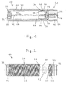
- FIG. 1 is a longitudinal section along the line 1 - 1 in FIG. 3 ,
- the connector 40 is connected to the housing sleeve 20 at a terminal end 24 in a manner described in more detail below.
- a sensor element 60 is arranged at a measuring end 22 opposite the connection end 22 of the housing sleeve 20 at a measuring end 22 opposite the connection end 22 of the housing sleeve 20, a sensor element 60 is arranged.
- the electronic sensor is an inductive sensor and, accordingly, the sensor element 60 is a sensor coil in a coil former.
- the inner lining 30 forms In the region of the measuring end 22 in the illustrated embodiment, a receptacle for the sensor element 60, so that a separate cup for the sensor element is not required here.
- an electronic assembly 70 with a circuit board 72 is present in the interior 28 of the housing sleeve 20 according to the invention.
- the printed circuit board 70 is held at the measuring end 22 by the sensor element 60 and at the connection end 24 by a receptacle formed in the connection body 50.
- the circuit board 72 carries components of a sensor electronics, which are not shown in detail. In the region of the connection end 24, the printed circuit board 72 projects into a receptacle formed in the connection body 50.
- LEDs 74 There are arranged on an upper and a lower side LEDs 74 on the circuit board 72, which are used to display optical status and / or measurement information.
- the housing sleeve 20 and the connecting sleeve 42 are made of metal and have a tubular or circular cylindrical shape. On its outer side, the housing sleeve 20 is provided with a thread 26, so that the sensor 10 can be screwed into a holder and optionally adjusted there.
- the connecting piece 40 is formed in the embodiment shown as a connector. That is, the ferrule 42, which may also be referred to as a lid, and the terminal body 50, which may also be referred to as a plastic inner liner, are configured to constitute the housing parts of a connector. In order to fix a connection cable, a thread 44 is also provided on an outer side of the connection sleeve 42.
- the inner lining 30 is closed on one side in the region of the measuring end of the housing sleeve 20, that is to say of the base housing, so that a lid-like closure 32 is formed there by the inner lining 30.
- a lid-like closure 32 is formed there by the inner lining 30.
- the sensor element 60 On the inside of this conclusion 32 is as out Fig. 1 can be seen, the sensor element 60 at.
- the termination 32 prevents vapors or other impurities from penetrating into the interior 28 of the sensor from the measuring end 22. This represents a significant advantage compared to the prior art.
- the connecting piece 40 is attached to the connecting end 24 of the housing sleeve 20 such that the connecting piece 40 seals with the inner lining 30.
- any housing assembly constitutes a potential weak point and is therefore unfavorable in principle from the viewpoint of as dense encapsulation as possible.
- the essential inventive approach is therefore to reduce the number of joints from the outset to a minimum.
- the connecting body 50 is also introduced into the connecting sleeve 42 by injection molding.
- the connection body 50 consists of a light-conducting plastic, so that optical information from the light-emitting diodes 74 can be conducted to the outside.
- a plurality of openings 49 are present in the connecting sleeve 42.
- the connecting sleeve 42 is formed so that the connecting body 50, the recesses 49 fills and forms transparent windows in this way.
- the connecting body 50 protrudes beyond the connecting sleeve 42 and forms an overhang 56. If openings are formed in a union nut to be screwed on, optical information can also be read there by a user because of the light-conducting properties of the connecting body 50.
- the housing sleeve 20 and the connecting sleeve 42 abut one another in a region 46 and are connected to one another in an undetachable manner after assembly, preferably welded. This can be done in particular by laser welding, whereby the heating caused by the welding is locally limited as far as possible and therefore the seal is not affected altogether.
- a circumferential weld seam 90 is formed during manufacture, so that as a result the seal as a whole can be further improved.
- a pre-fixing of the connecting sleeve 42 with respect to the housing sleeve 20 is achieved by a formed on the connecting sleeve 42 shoulder 48 with reduced outer diameter, which projects into the housing sleeve 20 and is guided by this.
- a sealing ring 80 is provided to provide the best possible seal between the housing sleeve 20 and the connector 40.
- a defined positioning of this Sealing ring 80 is made possible by a tubular extension 52 of the connecting body 50. How out Fig.
- the sealing ring 80 is pushed onto the pipe socket 52 prior to assembly and then the connector 40 is attached to the sealing ring 80 to the terminal end 24 of the housing sleeve 20 and the connecting sleeve 42 is welded to the housing sleeve 20.
- the housing sleeve 20 and the associated connector 40 are therefore designed so that they partially overlap and overlap in the assembled state and are sealed by a smallest possible number of seals, preferably by only a single functional seal, which is arranged in the region of the cover ,
- a defined receiving space for the sealing ring 80 is provided by a region 34 formed at the connection-side end of the inner lining 30 with reduced wall thickness. So that a coupling can be plugged with correct polarity onto the contact pins 76, a coding rib 58 is also provided on the inside of the connection body, which engages with a correspondingly shaped groove in a coupling element.
- Both the inner lining 30 and the connecting body 50 may be formed of an elastomeric material.
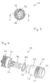
- FIGS. 5 and 6 a second embodiment of the sensor 10 according to the invention is shown.
- the connector 40 is designed as a cable outlet for the cable 78.
- a sealing lip 54 is formed on the connecting body 50 in the region in which it protrudes beyond the connecting sleeve 42.
- connection body 50 is slightly different from the connection body 50 of the first embodiment of FIGS. 1 to 4 educated. It has in its rear region a circumferential sealing device 53, which is provided with the cable sheath of the cable 78 for sealing the interior 28 of the sensor.
- the cable 78 is continued with its electrical lines except for the electrical assembly 70, in particular the printed circuit board 72, where it is connected to the existing components.
- a two-part strain relief 45 is additionally provided. This is mounted around the cable 78 and then inserted into the fitting 40. Here it comes to lie in the connection body 50, which in turn is designed to hold the strain relief 45 safely.
- the LEDs 74 are below the strain relief 45, so that it is also designed to be light-conducting, for example transparent, in order to forward the light signals of the LEDs 74 to the outside.
- a support ring 62 is provided, which is positioned in the assembled state in the contact region of the housing sleeve 20 with the connector 40.
- the support ring 62 supports on the one hand the sealing lip 54 so that it forms a sealing connection with the engagement portion 36, on the other hand, it also serves for a safer placement of the electronic assembly 70th
- a novel electronic sensor in which particularly good sealing properties are achieved by a reduced number of housing assemblies.
- the sensors according to the invention can be used particularly advantageously in areas where a high level of contamination is to be expected, for example in the food processing industry.
Landscapes
- Physics & Mathematics (AREA)
- General Physics & Mathematics (AREA)
- Connector Housings Or Holding Contact Members (AREA)
- Measuring Fluid Pressure (AREA)
- Investigating Or Analyzing Materials By The Use Of Electric Means (AREA)
- Casings For Electric Apparatus (AREA)
Priority Applications (2)
| Application Number | Priority Date | Filing Date | Title |
|---|---|---|---|
| EP08015398A EP2072967B1 (fr) | 2007-09-04 | 2008-09-01 | Capteur électronique et procédé de fabrication d'un capteur |
| US12/203,219 US8007170B2 (en) | 2007-09-04 | 2008-09-03 | Electronic sensor and method for the manufacture of a sensor |
Applications Claiming Priority (2)
| Application Number | Priority Date | Filing Date | Title |
|---|---|---|---|
| EP07017332A EP2034277A1 (fr) | 2007-09-04 | 2007-09-04 | Capteur électronique et procédé de fabrication d'un capteur |
| EP08015398A EP2072967B1 (fr) | 2007-09-04 | 2008-09-01 | Capteur électronique et procédé de fabrication d'un capteur |
Publications (2)
| Publication Number | Publication Date |
|---|---|
| EP2072967A1 true EP2072967A1 (fr) | 2009-06-24 |
| EP2072967B1 EP2072967B1 (fr) | 2010-03-17 |
Family
ID=39048898
Family Applications (2)
| Application Number | Title | Priority Date | Filing Date |
|---|---|---|---|
| EP07017332A Withdrawn EP2034277A1 (fr) | 2007-09-04 | 2007-09-04 | Capteur électronique et procédé de fabrication d'un capteur |
| EP08015398A Not-in-force EP2072967B1 (fr) | 2007-09-04 | 2008-09-01 | Capteur électronique et procédé de fabrication d'un capteur |
Family Applications Before (1)
| Application Number | Title | Priority Date | Filing Date |
|---|---|---|---|
| EP07017332A Withdrawn EP2034277A1 (fr) | 2007-09-04 | 2007-09-04 | Capteur électronique et procédé de fabrication d'un capteur |
Country Status (3)
| Country | Link |
|---|---|
| EP (2) | EP2034277A1 (fr) |
| AT (1) | ATE461429T1 (fr) |
| DE (1) | DE502008000450D1 (fr) |
Cited By (2)
| Publication number | Priority date | Publication date | Assignee | Title |
|---|---|---|---|---|
| WO2024170375A1 (fr) * | 2023-02-15 | 2024-08-22 | Pepperl + Fuchs Se | Capteur de proximité |
| DE102023125206A1 (de) * | 2023-09-18 | 2025-03-20 | Ifm Electronic Gmbh | Sensor mit Zustandsanzeige |
Families Citing this family (4)
| Publication number | Priority date | Publication date | Assignee | Title |
|---|---|---|---|---|
| DE102015103551A1 (de) * | 2015-03-11 | 2016-09-15 | Sick Ag | Steckerbaugruppe für einen Sensor und Verfahren zur Montage einer Steckerbaugruppe für einen Sensor |
| DE102015119557B4 (de) * | 2015-11-12 | 2022-11-10 | Sick Ag | Sensor |
| DE102017201711A1 (de) | 2017-02-02 | 2018-08-02 | Continental Teves Ag & Co. Ohg | Sensor mit einem Schutzgehäuse |
| CN118936825B (zh) * | 2024-08-23 | 2025-03-21 | 百林机电科技(苏州)有限公司 | 一种无线适配器模组 |
Citations (2)
| Publication number | Priority date | Publication date | Assignee | Title |
|---|---|---|---|---|
| DE10013218A1 (de) | 2000-03-17 | 2001-09-27 | Balluff Gebhard Feinmech | Verfahren zur Herstellung eines Positionssensors und Positionssensor |
| DE10237904B4 (de) | 2002-06-14 | 2007-05-31 | Ifm Electronic Gmbh | Elektronischer Sensor und Baueinheit aus einem elektronischen Sensor und einem Befestigungselement |
-
2007
- 2007-09-04 EP EP07017332A patent/EP2034277A1/fr not_active Withdrawn
-
2008
- 2008-09-01 DE DE502008000450T patent/DE502008000450D1/de active Active
- 2008-09-01 AT AT08015398T patent/ATE461429T1/de active
- 2008-09-01 EP EP08015398A patent/EP2072967B1/fr not_active Not-in-force
Patent Citations (2)
| Publication number | Priority date | Publication date | Assignee | Title |
|---|---|---|---|---|
| DE10013218A1 (de) | 2000-03-17 | 2001-09-27 | Balluff Gebhard Feinmech | Verfahren zur Herstellung eines Positionssensors und Positionssensor |
| DE10237904B4 (de) | 2002-06-14 | 2007-05-31 | Ifm Electronic Gmbh | Elektronischer Sensor und Baueinheit aus einem elektronischen Sensor und einem Befestigungselement |
Cited By (3)
| Publication number | Priority date | Publication date | Assignee | Title |
|---|---|---|---|---|
| WO2024170375A1 (fr) * | 2023-02-15 | 2024-08-22 | Pepperl + Fuchs Se | Capteur de proximité |
| DE102023103618B4 (de) * | 2023-02-15 | 2025-07-31 | Pepperl+Fuchs Se | Näherungssensor mit verbesserter Schlag- und Stoßfestigkeit |
| DE102023125206A1 (de) * | 2023-09-18 | 2025-03-20 | Ifm Electronic Gmbh | Sensor mit Zustandsanzeige |
Also Published As
| Publication number | Publication date |
|---|---|
| EP2034277A1 (fr) | 2009-03-11 |
| EP2072967B1 (fr) | 2010-03-17 |
| DE502008000450D1 (de) | 2010-04-29 |
| ATE461429T1 (de) | 2010-04-15 |
Similar Documents
| Publication | Publication Date | Title |
|---|---|---|
| EP2339312B1 (fr) | Dispositif d'étanchéité pour la fermeture d'un boîtier cellulaire de mesure de pression et ensemble cellulaire de mesure de pression muni de ce dispositif | |
| EP2072967B1 (fr) | Capteur électronique et procédé de fabrication d'un capteur | |
| DE19703206C2 (de) | Drucksensor-Bauteil mit Schlauchanschluß | |
| EP1169202B1 (fr) | Dispositif pour mesurer une pression de fluide | |
| DE102014009103B4 (de) | Drehmomentsensor-abdeckung | |
| DE112015000086T5 (de) | Raddrehzahlsensor und Herstellungsverfahren dafür | |
| DE102006006726A1 (de) | Elektrischer Steckverbinder | |
| WO2016087256A1 (fr) | Dispositif de détection | |
| DE102009028963A1 (de) | Anschlussanordnung für eine Sensoranordnung und Sensoranordnung | |
| DE102006008752B4 (de) | Verfahren zum Herstellen einer Komponente einer Fluiddruckmesseinheit, Verfahren zum Herstellen einer Fluiddruckmesseinheit, Komponente zum Einsatz in einer Fluiddruckmesseinheit sowie Fluiddruckmesseinheit | |
| DE102018124845A1 (de) | Sensoreinheit | |
| DE10039588B4 (de) | Gebereinrichtung | |
| DE202009009048U1 (de) | Sensorgehäusesystem | |
| DE102008061926B4 (de) | Langgestrecktes Metallelement zur Einspritzung in ein Bauteil | |
| DE102009002197A1 (de) | Befestigungseinrichtung für ein Kabel | |
| EP2574895B1 (fr) | Agencement de mesure destiné à la technique de mesure de processus et doté d'un raccord de processus universel | |
| EP3227641B1 (fr) | Dispositif de détection | |
| EP3479092B1 (fr) | Système d'essai pour boîtier antidéflagrant, boîtier antidéflagrant muni d'un système d'essai ainsi que procédé de fabrication et d'essai d'un boîtier antidéflagrant | |
| DE102007056545A1 (de) | Sensoranordnung zur Bestimmung eines Tankfüllstands und Tank mit Sensoranordnung | |
| EP2895779B1 (fr) | Dispositif pour relier deux conduites transportant du fluide | |
| DE10008885A1 (de) | Kupplung oder Stecker für eine Steckverbindung zur Anwendung in der Messtechnik, insbesondere in der Umweltmesstechnik | |
| EP3333554B1 (fr) | Dispositif destiné à afficher et/ou à réguler l'état d'un fluide | |
| DE3439784C2 (de) | Anordnung zur Einführung eines Kabels in ein Gehäuse | |
| EP3360496A1 (fr) | Raccordement de fluide et cryosonde le comprenant | |
| EP1193474A1 (fr) | Dispositif de mesure d' écoulements pour la détection magnétique-inductive ou capacitive des débits |
Legal Events
| Date | Code | Title | Description |
|---|---|---|---|
| PUAI | Public reference made under article 153(3) epc to a published international application that has entered the european phase |
Free format text: ORIGINAL CODE: 0009012 |
|
| AK | Designated contracting states |
Kind code of ref document: A1 Designated state(s): AT BE BG CH CY CZ DE DK EE ES FI FR GB GR HR HU IE IS IT LI LT LU LV MC MT NL NO PL PT RO SE SI SK TR |
|
| AX | Request for extension of the european patent |
Extension state: AL BA MK RS |
|
| 17P | Request for examination filed |
Effective date: 20090629 |
|
| GRAP | Despatch of communication of intention to grant a patent |
Free format text: ORIGINAL CODE: EPIDOSNIGR1 |
|
| GRAS | Grant fee paid |
Free format text: ORIGINAL CODE: EPIDOSNIGR3 |
|
| GRAA | (expected) grant |
Free format text: ORIGINAL CODE: 0009210 |
|
| AKX | Designation fees paid |
Designated state(s): AT BE BG CH CY CZ DE DK EE ES FI FR GB GR HR HU IE IS IT LI LT LU LV MC MT NL NO PL PT RO SE SI SK TR |
|
| AK | Designated contracting states |
Kind code of ref document: B1 Designated state(s): AT BE BG CH CY CZ DE DK EE ES FI FR GB GR HR HU IE IS IT LI LT LU LV MC MT NL NO PL PT RO SE SI SK TR |
|
| REG | Reference to a national code |
Ref country code: GB Ref legal event code: FG4D Free format text: NOT ENGLISH |
|
| REG | Reference to a national code |
Ref country code: CH Ref legal event code: EP |
|
| REG | Reference to a national code |
Ref country code: IE Ref legal event code: FG4D |
|
| REF | Corresponds to: |
Ref document number: 502008000450 Country of ref document: DE Date of ref document: 20100429 Kind code of ref document: P |
|
| REG | Reference to a national code |
Ref country code: CH Ref legal event code: NV Representative=s name: BOGENSBERGER PATENT- & MARKENBUERO DR. BURKHARD BO |
|
| REG | Reference to a national code |
Ref country code: NL Ref legal event code: VDEP Effective date: 20100317 |
|
| PG25 | Lapsed in a contracting state [announced via postgrant information from national office to epo] |
Ref country code: LT Free format text: LAPSE BECAUSE OF FAILURE TO SUBMIT A TRANSLATION OF THE DESCRIPTION OR TO PAY THE FEE WITHIN THE PRESCRIBED TIME-LIMIT Effective date: 20100317 Ref country code: HR Free format text: LAPSE BECAUSE OF FAILURE TO SUBMIT A TRANSLATION OF THE DESCRIPTION OR TO PAY THE FEE WITHIN THE PRESCRIBED TIME-LIMIT Effective date: 20100317 |
|
| LTIE | Lt: invalidation of european patent or patent extension |
Effective date: 20100317 |
|
| PG25 | Lapsed in a contracting state [announced via postgrant information from national office to epo] |
Ref country code: PL Free format text: LAPSE BECAUSE OF FAILURE TO SUBMIT A TRANSLATION OF THE DESCRIPTION OR TO PAY THE FEE WITHIN THE PRESCRIBED TIME-LIMIT Effective date: 20100317 Ref country code: FI Free format text: LAPSE BECAUSE OF FAILURE TO SUBMIT A TRANSLATION OF THE DESCRIPTION OR TO PAY THE FEE WITHIN THE PRESCRIBED TIME-LIMIT Effective date: 20100317 Ref country code: LV Free format text: LAPSE BECAUSE OF FAILURE TO SUBMIT A TRANSLATION OF THE DESCRIPTION OR TO PAY THE FEE WITHIN THE PRESCRIBED TIME-LIMIT Effective date: 20100317 Ref country code: SI Free format text: LAPSE BECAUSE OF FAILURE TO SUBMIT A TRANSLATION OF THE DESCRIPTION OR TO PAY THE FEE WITHIN THE PRESCRIBED TIME-LIMIT Effective date: 20100317 |
|
| REG | Reference to a national code |
Ref country code: IE Ref legal event code: FD4D |
|
| PG25 | Lapsed in a contracting state [announced via postgrant information from national office to epo] |
Ref country code: SE Free format text: LAPSE BECAUSE OF FAILURE TO SUBMIT A TRANSLATION OF THE DESCRIPTION OR TO PAY THE FEE WITHIN THE PRESCRIBED TIME-LIMIT Effective date: 20100317 Ref country code: GR Free format text: LAPSE BECAUSE OF FAILURE TO SUBMIT A TRANSLATION OF THE DESCRIPTION OR TO PAY THE FEE WITHIN THE PRESCRIBED TIME-LIMIT Effective date: 20100618 Ref country code: CY Free format text: LAPSE BECAUSE OF FAILURE TO SUBMIT A TRANSLATION OF THE DESCRIPTION OR TO PAY THE FEE WITHIN THE PRESCRIBED TIME-LIMIT Effective date: 20100317 Ref country code: EE Free format text: LAPSE BECAUSE OF FAILURE TO SUBMIT A TRANSLATION OF THE DESCRIPTION OR TO PAY THE FEE WITHIN THE PRESCRIBED TIME-LIMIT Effective date: 20100317 Ref country code: ES Free format text: LAPSE BECAUSE OF FAILURE TO SUBMIT A TRANSLATION OF THE DESCRIPTION OR TO PAY THE FEE WITHIN THE PRESCRIBED TIME-LIMIT Effective date: 20100628 Ref country code: RO Free format text: LAPSE BECAUSE OF FAILURE TO SUBMIT A TRANSLATION OF THE DESCRIPTION OR TO PAY THE FEE WITHIN THE PRESCRIBED TIME-LIMIT Effective date: 20100317 Ref country code: NL Free format text: LAPSE BECAUSE OF FAILURE TO SUBMIT A TRANSLATION OF THE DESCRIPTION OR TO PAY THE FEE WITHIN THE PRESCRIBED TIME-LIMIT Effective date: 20100317 |
|
| PG25 | Lapsed in a contracting state [announced via postgrant information from national office to epo] |
Ref country code: SK Free format text: LAPSE BECAUSE OF FAILURE TO SUBMIT A TRANSLATION OF THE DESCRIPTION OR TO PAY THE FEE WITHIN THE PRESCRIBED TIME-LIMIT Effective date: 20100317 Ref country code: IS Free format text: LAPSE BECAUSE OF FAILURE TO SUBMIT A TRANSLATION OF THE DESCRIPTION OR TO PAY THE FEE WITHIN THE PRESCRIBED TIME-LIMIT Effective date: 20100717 Ref country code: CZ Free format text: LAPSE BECAUSE OF FAILURE TO SUBMIT A TRANSLATION OF THE DESCRIPTION OR TO PAY THE FEE WITHIN THE PRESCRIBED TIME-LIMIT Effective date: 20100317 Ref country code: BG Free format text: LAPSE BECAUSE OF FAILURE TO SUBMIT A TRANSLATION OF THE DESCRIPTION OR TO PAY THE FEE WITHIN THE PRESCRIBED TIME-LIMIT Effective date: 20100617 |
|
| REG | Reference to a national code |
Ref country code: HU Ref legal event code: AG4A Ref document number: E008429 Country of ref document: HU |
|
| PLBE | No opposition filed within time limit |
Free format text: ORIGINAL CODE: 0009261 |
|
| STAA | Information on the status of an ep patent application or granted ep patent |
Free format text: STATUS: NO OPPOSITION FILED WITHIN TIME LIMIT |
|
| PG25 | Lapsed in a contracting state [announced via postgrant information from national office to epo] |
Ref country code: DK Free format text: LAPSE BECAUSE OF FAILURE TO SUBMIT A TRANSLATION OF THE DESCRIPTION OR TO PAY THE FEE WITHIN THE PRESCRIBED TIME-LIMIT Effective date: 20100317 Ref country code: IE Free format text: LAPSE BECAUSE OF FAILURE TO SUBMIT A TRANSLATION OF THE DESCRIPTION OR TO PAY THE FEE WITHIN THE PRESCRIBED TIME-LIMIT Effective date: 20100317 |
|
| 26N | No opposition filed |
Effective date: 20101220 |
|
| BERE | Be: lapsed |
Owner name: PEPPERL + FUCHS G.M.B.H. Effective date: 20100930 |
|
| PG25 | Lapsed in a contracting state [announced via postgrant information from national office to epo] |
Ref country code: MC Free format text: LAPSE BECAUSE OF NON-PAYMENT OF DUE FEES Effective date: 20100930 |
|
| PG25 | Lapsed in a contracting state [announced via postgrant information from national office to epo] |
Ref country code: BE Free format text: LAPSE BECAUSE OF NON-PAYMENT OF DUE FEES Effective date: 20100930 |
|
| PG25 | Lapsed in a contracting state [announced via postgrant information from national office to epo] |
Ref country code: MT Free format text: LAPSE BECAUSE OF FAILURE TO SUBMIT A TRANSLATION OF THE DESCRIPTION OR TO PAY THE FEE WITHIN THE PRESCRIBED TIME-LIMIT Effective date: 20100317 |
|
| PG25 | Lapsed in a contracting state [announced via postgrant information from national office to epo] |
Ref country code: NO Free format text: LAPSE BECAUSE OF FAILURE TO SUBMIT A TRANSLATION OF THE DESCRIPTION OR TO PAY THE FEE WITHIN THE PRESCRIBED TIME-LIMIT Effective date: 20100617 |
|
| PG25 | Lapsed in a contracting state [announced via postgrant information from national office to epo] |
Ref country code: LU Free format text: LAPSE BECAUSE OF NON-PAYMENT OF DUE FEES Effective date: 20100901 |
|
| PG25 | Lapsed in a contracting state [announced via postgrant information from national office to epo] |
Ref country code: TR Free format text: LAPSE BECAUSE OF FAILURE TO SUBMIT A TRANSLATION OF THE DESCRIPTION OR TO PAY THE FEE WITHIN THE PRESCRIBED TIME-LIMIT Effective date: 20100317 |
|
| REG | Reference to a national code |
Ref country code: CH Ref legal event code: PCAR Free format text: NEW ADDRESS: FALLSGASSE 7, 9492 ESCHEN (LI) |
|
| PG25 | Lapsed in a contracting state [announced via postgrant information from national office to epo] |
Ref country code: PT Free format text: LAPSE BECAUSE OF NON-PAYMENT OF DUE FEES Effective date: 20100317 |
|
| REG | Reference to a national code |
Ref country code: FR Ref legal event code: PLFP Year of fee payment: 8 |
|
| PGFP | Annual fee paid to national office [announced via postgrant information from national office to epo] |
Ref country code: GB Payment date: 20150928 Year of fee payment: 8 |
|
| PGFP | Annual fee paid to national office [announced via postgrant information from national office to epo] |
Ref country code: AT Payment date: 20150930 Year of fee payment: 8 |
|
| PGFP | Annual fee paid to national office [announced via postgrant information from national office to epo] |
Ref country code: CH Payment date: 20150928 Year of fee payment: 8 Ref country code: IT Payment date: 20150925 Year of fee payment: 8 |
|
| PGFP | Annual fee paid to national office [announced via postgrant information from national office to epo] |
Ref country code: HU Payment date: 20151120 Year of fee payment: 8 Ref country code: FR Payment date: 20150929 Year of fee payment: 8 |
|
| REG | Reference to a national code |
Ref country code: CH Ref legal event code: PL |
|
| REG | Reference to a national code |
Ref country code: AT Ref legal event code: MM01 Ref document number: 461429 Country of ref document: AT Kind code of ref document: T Effective date: 20160901 |
|
| GBPC | Gb: european patent ceased through non-payment of renewal fee |
Effective date: 20160901 |
|
| REG | Reference to a national code |
Ref country code: FR Ref legal event code: ST Effective date: 20170531 |
|
| PG25 | Lapsed in a contracting state [announced via postgrant information from national office to epo] |
Ref country code: FR Free format text: LAPSE BECAUSE OF NON-PAYMENT OF DUE FEES Effective date: 20160930 Ref country code: GB Free format text: LAPSE BECAUSE OF NON-PAYMENT OF DUE FEES Effective date: 20160901 Ref country code: CH Free format text: LAPSE BECAUSE OF NON-PAYMENT OF DUE FEES Effective date: 20160930 Ref country code: LI Free format text: LAPSE BECAUSE OF NON-PAYMENT OF DUE FEES Effective date: 20160930 |
|
| PG25 | Lapsed in a contracting state [announced via postgrant information from national office to epo] |
Ref country code: AT Free format text: LAPSE BECAUSE OF NON-PAYMENT OF DUE FEES Effective date: 20160901 Ref country code: HU Free format text: LAPSE BECAUSE OF NON-PAYMENT OF DUE FEES Effective date: 20160902 Ref country code: IT Free format text: LAPSE BECAUSE OF NON-PAYMENT OF DUE FEES Effective date: 20160901 |
|
| REG | Reference to a national code |
Ref country code: DE Ref legal event code: R082 Ref document number: 502008000450 Country of ref document: DE Representative=s name: SCHIFFER, AXEL, DIPL.-PHYS.UNIV. DR.RER.NAT., DE |
|
| PGFP | Annual fee paid to national office [announced via postgrant information from national office to epo] |
Ref country code: DE Payment date: 20190930 Year of fee payment: 12 |
|
| REG | Reference to a national code |
Ref country code: DE Ref legal event code: R119 Ref document number: 502008000450 Country of ref document: DE |
|
| PG25 | Lapsed in a contracting state [announced via postgrant information from national office to epo] |
Ref country code: DE Free format text: LAPSE BECAUSE OF NON-PAYMENT OF DUE FEES Effective date: 20210401 |