EP2073031A2 - Bloc-batterie, dispositif portable, procédé de détection de court-circuit interne et programme de détection de court-circuit interne - Google Patents
Bloc-batterie, dispositif portable, procédé de détection de court-circuit interne et programme de détection de court-circuit interne Download PDFInfo
- Publication number
- EP2073031A2 EP2073031A2 EP08171862A EP08171862A EP2073031A2 EP 2073031 A2 EP2073031 A2 EP 2073031A2 EP 08171862 A EP08171862 A EP 08171862A EP 08171862 A EP08171862 A EP 08171862A EP 2073031 A2 EP2073031 A2 EP 2073031A2
- Authority
- EP
- European Patent Office
- Prior art keywords
- unit
- battery unit
- battery
- voltage
- value
- Prior art date
- Legal status (The legal status is an assumption and is not a legal conclusion. Google has not performed a legal analysis and makes no representation as to the accuracy of the status listed.)
- Withdrawn
Links
Images





Classifications
-
- G—PHYSICS
- G01—MEASURING; TESTING
- G01R—MEASURING ELECTRIC VARIABLES; MEASURING MAGNETIC VARIABLES
- G01R31/00—Arrangements for testing electric properties; Arrangements for locating electric faults; Arrangements for electrical testing characterised by what is being tested not provided for elsewhere
- G01R31/36—Arrangements for testing, measuring or monitoring the electrical condition of accumulators or electric batteries, e.g. capacity or state of charge [SoC]
- G01R31/382—Arrangements for monitoring battery or accumulator variables, e.g. SoC
- G01R31/3842—Arrangements for monitoring battery or accumulator variables, e.g. SoC combining voltage and current measurements
-
- G—PHYSICS
- G01—MEASURING; TESTING
- G01R—MEASURING ELECTRIC VARIABLES; MEASURING MAGNETIC VARIABLES
- G01R31/00—Arrangements for testing electric properties; Arrangements for locating electric faults; Arrangements for electrical testing characterised by what is being tested not provided for elsewhere
- G01R31/36—Arrangements for testing, measuring or monitoring the electrical condition of accumulators or electric batteries, e.g. capacity or state of charge [SoC]
- G01R31/385—Arrangements for measuring battery or accumulator variables
- G01R31/387—Determining ampere-hour charge capacity or SoC
- G01R31/388—Determining ampere-hour charge capacity or SoC involving voltage measurements
-
- H—ELECTRICITY
- H01—ELECTRIC ELEMENTS
- H01M—PROCESSES OR MEANS, e.g. BATTERIES, FOR THE DIRECT CONVERSION OF CHEMICAL ENERGY INTO ELECTRICAL ENERGY
- H01M10/00—Secondary cells; Manufacture thereof
- H01M10/42—Methods or arrangements for servicing or maintenance of secondary cells or secondary half-cells
- H01M10/44—Methods for charging or discharging
-
- H—ELECTRICITY
- H01—ELECTRIC ELEMENTS
- H01M—PROCESSES OR MEANS, e.g. BATTERIES, FOR THE DIRECT CONVERSION OF CHEMICAL ENERGY INTO ELECTRICAL ENERGY
- H01M10/00—Secondary cells; Manufacture thereof
- H01M10/42—Methods or arrangements for servicing or maintenance of secondary cells or secondary half-cells
- H01M10/44—Methods for charging or discharging
- H01M10/441—Methods for charging or discharging for several batteries or cells simultaneously or sequentially
-
- H—ELECTRICITY
- H01—ELECTRIC ELEMENTS
- H01M—PROCESSES OR MEANS, e.g. BATTERIES, FOR THE DIRECT CONVERSION OF CHEMICAL ENERGY INTO ELECTRICAL ENERGY
- H01M10/00—Secondary cells; Manufacture thereof
- H01M10/42—Methods or arrangements for servicing or maintenance of secondary cells or secondary half-cells
- H01M10/44—Methods for charging or discharging
- H01M10/443—Methods for charging or discharging in response to temperature
-
- H—ELECTRICITY
- H01—ELECTRIC ELEMENTS
- H01M—PROCESSES OR MEANS, e.g. BATTERIES, FOR THE DIRECT CONVERSION OF CHEMICAL ENERGY INTO ELECTRICAL ENERGY
- H01M10/00—Secondary cells; Manufacture thereof
- H01M10/42—Methods or arrangements for servicing or maintenance of secondary cells or secondary half-cells
- H01M10/46—Accumulators structurally combined with charging apparatus
-
- H—ELECTRICITY
- H01—ELECTRIC ELEMENTS
- H01M—PROCESSES OR MEANS, e.g. BATTERIES, FOR THE DIRECT CONVERSION OF CHEMICAL ENERGY INTO ELECTRICAL ENERGY
- H01M10/00—Secondary cells; Manufacture thereof
- H01M10/42—Methods or arrangements for servicing or maintenance of secondary cells or secondary half-cells
- H01M10/48—Accumulators combined with arrangements for measuring, testing or indicating the condition of cells, e.g. the level or density of the electrolyte
- H01M10/482—Accumulators combined with arrangements for measuring, testing or indicating the condition of cells, e.g. the level or density of the electrolyte for several batteries or cells simultaneously or sequentially
-
- H—ELECTRICITY
- H01—ELECTRIC ELEMENTS
- H01M—PROCESSES OR MEANS, e.g. BATTERIES, FOR THE DIRECT CONVERSION OF CHEMICAL ENERGY INTO ELECTRICAL ENERGY
- H01M10/00—Secondary cells; Manufacture thereof
- H01M10/42—Methods or arrangements for servicing or maintenance of secondary cells or secondary half-cells
- H01M10/48—Accumulators combined with arrangements for measuring, testing or indicating the condition of cells, e.g. the level or density of the electrolyte
- H01M10/486—Accumulators combined with arrangements for measuring, testing or indicating the condition of cells, e.g. the level or density of the electrolyte for measuring temperature
-
- G—PHYSICS
- G01—MEASURING; TESTING
- G01R—MEASURING ELECTRIC VARIABLES; MEASURING MAGNETIC VARIABLES
- G01R31/00—Arrangements for testing electric properties; Arrangements for locating electric faults; Arrangements for electrical testing characterised by what is being tested not provided for elsewhere
- G01R31/50—Testing of electric apparatus, lines, cables or components for short-circuits, continuity, leakage current or incorrect line connections
- G01R31/52—Testing for short-circuits, leakage current or ground faults
-
- H—ELECTRICITY
- H01—ELECTRIC ELEMENTS
- H01M—PROCESSES OR MEANS, e.g. BATTERIES, FOR THE DIRECT CONVERSION OF CHEMICAL ENERGY INTO ELECTRICAL ENERGY
- H01M10/00—Secondary cells; Manufacture thereof
- H01M10/05—Accumulators with non-aqueous electrolyte
- H01M10/052—Li-accumulators
- H01M10/0525—Rocking-chair batteries, i.e. batteries with lithium insertion or intercalation in both electrodes; Lithium-ion batteries
-
- Y—GENERAL TAGGING OF NEW TECHNOLOGICAL DEVELOPMENTS; GENERAL TAGGING OF CROSS-SECTIONAL TECHNOLOGIES SPANNING OVER SEVERAL SECTIONS OF THE IPC; TECHNICAL SUBJECTS COVERED BY FORMER USPC CROSS-REFERENCE ART COLLECTIONS [XRACs] AND DIGESTS
- Y02—TECHNOLOGIES OR APPLICATIONS FOR MITIGATION OR ADAPTATION AGAINST CLIMATE CHANGE
- Y02E—REDUCTION OF GREENHOUSE GAS [GHG] EMISSIONS, RELATED TO ENERGY GENERATION, TRANSMISSION OR DISTRIBUTION
- Y02E60/00—Enabling technologies; Technologies with a potential or indirect contribution to GHG emissions mitigation
- Y02E60/10—Energy storage using batteries
Definitions
- This invention relates to a battery pack which detects an internal short-circuit in a battery unit contained in the battery pack, a portable device including a battery pack, an internal short detecting method for detecting an internal short-circuit in a battery pack, and an internal short detection program.
- a portable device such as a digital camera, carries a battery unit in which two or more lithium ion batteries as secondary batteries are connected together. Because lithium ion batteries are prone to overcharging or overdischarging, the lithium ion batteries are arranged with a battery pack containing a protection circuit for protecting the batteries from overcharging or overdischarging.
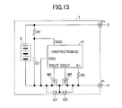
- FIG. 13 shows the composition of a battery pack 1 according to the related art.
- a battery unit 2 in which a plurality of lithium ion batteries are connected together is connected in parallel with a series circuit in which a capacitor Cl and a resistor R1 are connected in series.
- a positive electrode of the battery unit 2 is connected to an external terminal 3 of the battery pack 1, and a negative electrode of the battery unit 2 is connected to an external terminal 4 of the battery pack 1 via a pair of n channel MOS (metal oxide semiconductor) transistors M1 and M2 for current interception.
- MOS metal oxide semiconductor
- the drains of the MOS transistors M1 and M2 are connected to each other, the source of the MOS transistor M1 is connected to the negative electrode of the battery unit 2, and the source of the MOS transistor M2 is connected to the external terminal 4.
- Body diodes D1 and D2 are connected between the drain and the source of each of the MOS transistors M1 and M2 respectively in an equivalent manner.
- a protection IC (integrated circuit) 5 is arranged in the battery pack 1 so that the protection IC 5 includes an overcharge detecting circuit, an overdischarge detecting circuit, and an overcurrent detecting circuit.
- a power-source voltage Vdd is supplied to the protection IC 5 through the resistor R1 from the positive electrode of the battery unit 2, and a power-source voltage Vss is supplied to the protection IC 5 from the negative electrode of the battery unit 2, so that the protection IC 5 operates.
- the protection IC 5 sets the output signal DOUT to the low level to turn the MOS transistor M1 to an OFF state.
- the protection IC 5 sets the output signal COUT to the low level to turn the MOS transistor M2 to the OFF state.
- the battery pack of the above type may be arranged to have additional functions, including a function of detecting the battery remaining quantity of the battery unit, and a function of detecting whether the lithium ion batteries contained in the battery unit are the standard products.
- Japanese Laid-Open Patent Application No. 2006-92850 discloses a battery pack which carries a protection module provided with a function of detecting battery chargers supplied from non-authorized parties.
- the above-described battery pack according to the related art does not have a function of protecting the batteries from short-circuit which may take place in the battery unit. Even if the above battery pack can protect the lithium ion batteries from overcharging and overdischarging, it is difficult to secure safety when short-circuit takes place in the battery unit. Therefore, when an internal short-circuit occurs in the battery unit due to a manufacturing defect, due to a deposition of metal lithium through overdischarging of the batteries, or due to mechanical impact or stress of the batteries, the above-described battery pack according to the related art may involve a risk of resulting in an accident, such as an explosion or a burst.
- the present disclosure provides an improved battery pack in which the above-described problems are eliminated.
- the present disclosure provides a battery pack which is able to secure safety when a short-circuit takes place inside a battery unit containing a plurality of secondary batteries.
- the present disclosure provides a battery pack including a battery unit containing a plurality of chargeable and dischargeable secondary batteries, the battery pack comprising: a current detecting unit configured to detect a current which flows in the battery unit; a voltage detecting unit configured to detect a voltage of the battery unit; and a short detecting unit configured to detect an internal short-circuit in the battery unit, wherein the short detecting unit is configured to determine that an internal short-circuit in the battery unit occurs, when a difference between a first voltage of the battery unit detected at a time a current flowing in the battery unit is below a predetermined current value and a second voltage of the battery unit detected at a time after a predetermined period has elapsed while the current flowing in the battery unit is below the predetermined current value is larger than a predetermined voltage difference value.
- the above-mentioned battery pack may be arranged to further comprise a capacity value acquiring unit configured to acquire an available capacity value of the battery unit, based on a voltage detected by the voltage detecting unit, wherein the short detecting unit is configured to determine that an internal short-circuit in the battery unit occurs, when a difference between a first available capacity value of the battery unit acquired at a time a current flowing in the battery unit is below the predetermined current value and a second available capacity value of the battery unit acquired at a time after a predetermined period has elapsed while the current flowing in the battery unit is below the predetermined current value is larger than a predetermined value.
- a capacity value acquiring unit configured to acquire an available capacity value of the battery unit, based on a voltage detected by the voltage detecting unit, wherein the short detecting unit is configured to determine that an internal short-circuit in the battery unit occurs, when a difference between a first available capacity value of the battery unit acquired at a time a current flowing in the battery unit is below the predetermined current value and
- the above-mentioned battery pack may be arranged to further comprise: a temperature detecting unit configured to detect a temperature of the battery unit; and a temperature compensation unit configured to correct a voltage detected by the voltage detecting unit based on a temperature detected by the temperature detecting unit, wherein the capacity value acquiring unit is configured to acquire an available capacity value of the battery unit based on the voltage corrected by the temperature compensation unit.
- the above-mentioned battery pack may be arranged to further comprise a current value computing unit configured to compute a value of a current consumed during a predetermined period, based on a difference between a first available capacity value of the battery unit acquired at a time a current flowing in the battery unit is below the predetermined current value and a second available capacity value of the battery unit acquired at a time after the predetermined period has elapsed while the current flowing in the battery unit is below the predetermined current value, wherein the short detecting unit is configured to determine that an internal short-circuit in the battery unit occurs, when the value of the current computed by the current value computing unit is larger than a reference value.
- the above-mentioned battery pack may be arranged to further comprise a communication unit configured to communicate with a portable device in which the battery pack is arranged, wherein the communication unit outputs a notice of internal short detection to the portable device when it is determined by the short detecting unit that an internal short-circuit in the battery unit occurs.
- the present disclosure provides a portable device in which a battery pack is arranged, the battery pack including a battery unit containing a plurality of chargeable and dischargeable secondary batteries, the battery pack comprising: a current detecting unit configured to detect a current which flows in the battery unit; a voltage detecting unit configured to detect a voltage of the battery unit; and a short detecting unit configured to detect an internal short-circuit in the battery unit, wherein the short detecting unit is configured to determine that an internal short-circuit in the battery unit occurs, when a difference between a first voltage of the battery unit detected at a time a current flowing in the battery unit is below a predetermined current value and a second voltage of the battery unit detected at a time after a predetermined period has elapsed while the current flowing in the battery unit is below the predetermined current value is larger than a predetermined voltage difference value.
- the present disclosure provides a short detecting method for use in a battery pack including a battery unit containing a plurality of chargeable and dischargeable secondary batteries, the short detecting method comprising: detecting a current which flows in the battery unit; detecting a voltage of the battery unit; and detecting an internal short-circuit in the battery unit, wherein the detecting the internal short-circuit in the battery unit is configured to determine that an internal short-circuit in the battery unit occurs, when a difference between a first voltage of the battery unit detected at a time a current flowing in the battery unit is below a predetermined current value and a second voltage of the battery unit detected at a time after a predetermined period has elapsed while the current flowing in the battery unit is below the predetermined current value is larger than a predetermined voltage difference value.
- the battery pack of the embodiment of the invention is arranged to detect a first voltage of a battery unit containing a plurality of secondary batteries when charging and discharging of the battery unit is stopped, detect a second voltage of the battery unit when a predetermined period has elapsed after the time the charging and discharging of the battery unit is stopped, and determine whether an internal short-circuit occurs in the battery unit based on a voltage difference between the first voltage and the second voltage.
- the portable device of the embodiment of the invention is arranged to restrict operation of a main part of the portable device in response to a notice of internal short-circuit received from the battery pack.
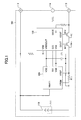
- FIG. 1 is a diagram showing the composition of a battery pack 100 of a first embodiment of the invention.
- the battery pack 100 includes a battery unit 111 in which a plurality of secondary batteries 110, such as lithium ion batteries, are connected together.
- the battery unit 111 in this embodiment is arranged so that the secondary batteries 110 are connected in series.
- the present invention is not limited to this embodiment.
- the battery pack 100 has a positive electrode terminal 112 and a negative electrode terminal 113 for connecting the battery pack 100 with a portable device (which will be described later) incorporating the battery pack 100 therein.
- the battery pack 100 includes a short detection IC 120 and a protection IC 130 which are arranged between the battery unit 111 and the positive and negative terminals 112, 113.
- the short detection IC 120 has a power-source voltage terminal VDD, a reference voltage terminal VSS, a voltage detection terminal VBAT1, a pair of current detection terminals VRSP, VRSM, and a communication terminal SIO.
- the short detection IC 120 receives from the power-source voltage terminal VDD a voltage which is generated from the battery voltage regulated in the protection IC 130.
- the reference voltage terminal VSS of the short detection IC 120 is connected directly to the negative electrode of the battery unit 111.
- the short detection IC 120 detects an internal short-circuit in the battery unit 111. Specifically, the short detection IC 120 detects an output voltage of the battery unit 111 from the voltage detection terminal VBAT1 which is connected to the positive electrode of the battery unit 111.
- the current detection terminal VRSM (one of the pair) is connected to the negative electrode of the battery unit 111, and connected further to the current detection terminal VRSP (the other of the pair) through a resistor R11 arranged outside the short detection IC 120.
- the short detection IC 120 detects a charging or discharging current of the battery unit 111 (i.e., a current which flows into the external resistor R11) through the current detection terminals VRSP and VRSM.
- the communication terminal SIO of the short detection IC 120 is connected through the protection IC 130 to an external terminal 114, and the external terminal 114 is used to allow the battery pack 100 to communicate with the portable device.
- the short detection IC 120 communicates with the portable device through the communication terminal SIO and the protection IC 130.
- the protection IC 130 has a terminal DOUT and a terminal COUT which are respectively connected to the gate of an n channel MOS transistor M11 and the gate of an n channel MOS transistor M12, and the MOS transistors M11 and M12 are arranged to intercept the charging and discharging of the battery pack 100.
- the protection IC 130 sets the output signal DOUT to the low level to turn the MOS transistor M11 to an OFF state.
- the protection IC 130 sets the output signal COUT to the low level to turn the MOS transistor M12 to the OFF state.
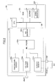
- FIG. 2 is a diagram showing the hardware composition of the short detection IC 120 of the first embodiment.
- the short detection IC 120 of FIG. 2 includes a CPU (central processing unit) 121, a sensor unit 122, an ROM (read only memory) 123, an EEPROM (electrically erasable and programmable ROM) 124, and a serial interface (I/F) 125.
- CPU central processing unit
- sensor unit 122
- ROM read only memory
- EEPROM electrically erasable and programmable ROM
- serial interface I/F
- the CPU 121 controls the respective units of the short detection IC 120.
- the sensor unit 122 detects a voltage, a current, and a temperature of the battery unit 111 (see FIG. 1 ).
- the ROM 123 stores a program which is executed by the CPU 121 to control the respective units of the short detection IC 120.
- the EEPROM 124 stores information indicating respective parameters including the voltage, the current, and the temperature of the battery unit 111 detected by the sensor unit 122, and information indicating an authentication ID for performing authentication between the battery pack and the portable device.
- the serial interface 125 enables the short detection IC 120 to communicate with the portable device through the communication terminal SIO.
- the CPU 121 the sensor unit 122, the ROM 123, the EEPROM 124, and the serial interface 125 are interconnected by a bus 126, and these elements can exchange the data and the program between them.
- the sensor unit 122 includes a temperature sensor 122a, a voltage sensor 122b, a current sensor 122c, a multiplexer 122d, and an analog-to-digital (A/D) converter 122e.
- the temperature sensor 122a detects a temperature of the battery unit 111.
- the voltage sensor 122b detects an output voltage of the battery unit 111 through the voltage detection terminal VBAT1 connected to the battery unit 111.
- the current sensor 122c detects a charging or discharging current of the battery unit 111 (i.e., a current which flows into the external resistor R11) through the current detection terminals VRSP and VRSM.
- the respective outputs of the temperature sensor 122a, the voltage sensor 122b, and the current sensor 122c are connected to the multiplexer 122d, and the multiplexer 122d outputs an analog signal.
- the A/D converter 122e converts the analog signal output by the multiplexer 122d into a digital signal.
- FIG. 3 is a block diagram showing the functional composition of the short detection IC 120 of the first embodiment.
- the functional composition of the short detection IC 120 shown in FIG. 3 is embodied by the program read from the ROM 123 shown in FIG. 2 .
- the hardware module which embodies the functional composition of FIG. 3 may be arranged separately from the elements of the hardware composition of FIG. 2 .
- the short detection IC 120 of the first embodiment includes a current value acquiring unit 210, a voltage value acquiring unit 220, a timer unit 230, a short detecting unit 240, a storage control unit 250, a communication unit 260, and a display control unit 270.
- the current value acquiring unit 210 is configured to acquire a current value detected by the current sensor 122c.
- the voltage value acquiring unit 220 is configured to acquire a voltage value detected by the voltage sensor 122b.
- the timer unit 230 is configured to measure a time by using the clock function provided in the short detection IC 120.
- the short detecting unit 240 is configured to detect an internal short-circuit in the battery unit 111, based on the current value acquired by the current value acquiring unit 210, the voltage value acquired by the voltage value acquiring unit 220, and the time measured by the timer unit 230.
- the storage control unit 250 is configured to store, into the EEPROM 124, the parameters including the current value acquired by the current value acquiring unit 210 and the voltage value acquired by the voltage value acquiring unit 220.
- the communication unit 260 is configured to communicate with the portable device in which the battery pack 100 is provided.
- the display control unit 270 is configured to display a message indicating that an internal short-circuit occurs in the battery unit 111, when it is detected by the short detecting unit 240.
- the storage control unit 250 is caused to store a corresponding first voltage value acquired by the voltage value acquiring unit 220 into the EEPROM 124. And after a predetermined period has elapsed while the state in which the acquired current value is below the predetermined value is continued, a second voltage value is acquired again by the voltage value acquiring unit 220.
- a difference between the first voltage value previously stored in the EEPROM 124 and the second voltage value currently acquired by the voltage value acquiring unit 220 is above a predetermined value, it is determined that an internal short-circuit is occurring in the battery unit 111.
- FIG. 4A, FIG. 4B and FIG. 4C are diagrams showing a current waveform and a voltage waveform at the time of charging the battery unit 111 in the battery pack 100.
- FIG. 5A, FIG. 5B and FIG. 5C are diagrams showing a current waveform and a voltage waveform at the time of discharging the battery unit 111 in the battery pack 100.
- FIG. 4A shows a current waveform at the time of charging the battery unit 111
- FIG. 4B shows a voltage waveform at the time of charging the battery unit 111 when no internal short-circuit occurs in the battery unit 111
- FIG. 4C shows a voltage waveform at the time of charging the battery unit 111 when an internal short-circuit occurs in the battery unit 111.
- the battery unit 111 is charged by receiving the constant current In as shown in FIG. 4A , and the voltage of the battery unit 111 is gradually increased from a voltage value V1 to a voltage value V2.
- the voltage value starts decreasing and, after a predetermined time t1 has elapsed, the voltage of the battery unit 111 is stabilized at an intermediate voltage value V3 (refer to FIG. 4B ).
- FIG. 5A shows a current waveform at the time of discharging the battery unit 111
- FIG. 5B shows a voltage waveform at the time of discharging the battery unit 111 when no internal short-circuit occurs in the battery unit 111
- FIG. 5C shows a voltage waveform at the time of discharging the battery unit 111 when an internal short-circuit occurs in the battery unit 111.
- the battery unit 111 is discharged by outputting the constant current In as shown in FIG. 5A , and the voltage of the battery unit 111 is gradually decreased from a voltage value V4 to a voltage value V5.
- the voltage value starts increasing and, after a predetermined time t2 has elapsed, the voltage of the battery unit 111 is stabilized at an intermediate voltage value V6 (refer to FIG. 5B ).
- the short detection IC 120 of the first embodiment the occurrence of an internal short-circuit in the battery unit 111 is detected by making use of the characteristics of the battery unit 111 described above with FIGs. 4A to 5C .
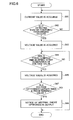
- FIG. 6 is a flowchart for explaining operation of the short detection IC 120 of the first embodiment.
- the short detection IC 120 causes the current value acquiring unit 210 to acquire a current value detected by the current sensor 122c (S61).
- the short detecting unit 240 determines whether charging or discharging of the battery unit 111 is performed, based on the current value acquired in step S61.
- the short detecting unit 240 compares the current value acquired in step S61 with a predetermined current value which is stored beforehand in the ROM 123. When the current value acquired in step S61 is below the predetermined current value, it is determined that charging or discharging of the battery unit 111 is not performed.
- the predetermined current value is a value used for detecting the state in which charging or discharging of the battery unit 111 is stopped. Therefore, it is preferred that the predetermined current value is sufficiently smaller than a current value when charging or discharging of the battery unit 111 is performed.
- the predetermined current value is distinct from the standby current.
- the standby current which flows in the battery pack 100 in this embodiment when it is arranged in a portable device is about 1 mA. Therefore, the predetermined current value may be set to about 10 mA.
- the standby current means the current which flows in a waiting state of the portable device in a case in which the portable device is a cellular phone.
- the short detecting unit 240 determines that charging or discharging is not performed (S62). At this time, the short detection IC 120 causes the voltage value acquiring unit 220 to acquire a voltage value Va detected by the voltage sensor 122b (S63).
- the short detection IC 120 causes the storage control unit 250 to store the acquired voltage value Va and time information indicating the time the voltage value Va is acquired, into the EEPROM 124, for example.
- the time information is acquired by using the clock function provided in the short detection IC 120.
- the short detecting unit 240 determines whether a predetermined period has elapsed after the acquisition of the voltage value Va in step S63 (S64). Specifically, the short detecting unit 240 compares a period from the instant the voltage value Va is stored in the EEPROM 124 to the instant the subsequently elapsed time is measured by the timer unit 230, with the predetermined period.
- the predetermined period may be set to either the time t1 in FIG. 4B or the time t2 in FIG. 5B .
- the predetermined period indicates the period from the instant charging or discharging of the battery unit 111 is stopped to the instant the voltage value is stabilized when no internal short-circuit occurs in the battery unit 111.
- the predetermined time may be set to the longer one of the time t1 and the time t2.
- the predetermined period may be stored beforehand in the ROM 123.
- the predetermined period in this embodiment may be set to, for example, 5 hours.
- the short detection IC 120 causes the voltage value acquiring unit 220 to acquire again a voltage value Vb detected by the voltage sensor 122b (S65).
- the short detecting unit 240 compares the voltage value Va acquired in step S63 and the voltage value Vb acquired in step S65, and determines whether a difference between the voltage value Va and the voltage value Vb is larger than a predetermined value (S67).
- the predetermined value is a reference value used for determining that the voltage value is not yet stabilized.
- the predetermined value may be stored in the ROM 123 beforehand.
- the predetermined value may be set to the value indicating (V2-V3) in the example of FIGs. 4A to 4C or set to the value indicating (V6-V5) in the example of FIGs. 5A to 5C .
- the short detecting unit 240 determines that an internal short-circuit occurs in the battery unit 111. In this case, the short detecting unit 240 notifies the communication unit 260 of the occurrence of an internal short-circuit in the battery unit 111. The communication unit 260 outputs a notice of internal short detection to the portable device (S68).
- the notice of internal short detection is transmitted from the communication terminal SIO of the short detection IC 120 to the portable device via the protection IC 130.
- the above embodiment may be arranged so that, when an internal short-circuit is detected, the display control unit 270 displays a message indicating the detection of the internal short-circuit.
- the display control unit 270 may cause the LED (light-emitting diode) in the battery pack 100 to be turned ON, indicating that an internal short-circuit in the battery unit 111 is detected.
- an internal short-circuit in the battery unit 111 can be detected as described above.
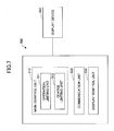
- FIG. 7 is a diagram showing the composition of a portable device 300 of an embodiment of the invention.
- the battery pack 100 shown in FIG. 1 is arranged, and, when an internal short-circuit in the battery unit 111 is detected by the battery pack 100, the battery pack 100 outputs a notice of internal short detection to the portable device 300, and operation of the main part of the portable device 300 can be controlled in response to this notice.
- the portable device 300 examples are a cellular phone, a digital camera, etc. Namely, the portable device 300 is an electronic device which is driven by electric power supplied by the battery pack 100.
- the portable device 300 restricts operation of the portable device 300. If an internal short-circuit in the battery unit 111 is detected, the portable device 300 can restrict the charging operation to the battery pack 100.
- the portable device 300 includes a processing unit and a storage device (which are not shown in FIG. 7 ), and the functions of respective units of the portable device 300 (which will be explained below) are carried out by causing the processing unit to execute a specific program read from the storage device.
- the portable device 300 includes a main control unit 310, a communication unit 320, and a display control unit 330.
- the main control unit 310 controls operation of the portable device 300.
- the main control unit 310 includes an operation limiting unit 311 and a charge limiting unit 312.
- the operation limiting unit 311 restricts operation of the portable device 300 in response to a notice of internal short detection from the battery pack 100.
- the charge limiting unit 312 restricts the charging operation to the battery pack 100 in response to a notice of internal short detection from the battery pack 100.
- the communication unit 320 performs communication with the battery pack 100. Specifically, the communication unit 320 is connected to the battery pack 100 and performs communication with the short detection IC 120 via the protection IC 130 provided in the battery pack 100.
- the display control unit 330 controls the displaying of messages or operational indications on a display device 340 which is provided in the portable device 300.
- the display device 340 is a liquid crystal display device provided in the portable device 300.
- the main control unit 310 performs the operation restriction or charging operation of the portable device 300.
- the setting data relating to the operation restriction and charging restriction of the portable device 300 is stored beforehand in the storage device (which is not illustrated).
- the main control unit 310 reads out the setting data in response to the notice of internal short detection, and performs the operation restriction or charging restriction of the portable device 300.
- the main control unit 310 may cause the operation limiting unit 311 to intercept the power supply of the portable device 300 in response to a notice of internal short detection.
- the main control unit 310 may cause the operation limiting unit 311 to inhibit operation of the operation button (not shown) provided in the portable device 300.
- the main control unit 310 may cause the charge limiting unit 312 to stop the charging of the battery pack 100.
- the display control unit 330 displays a message indicating that an internal short-circuit in the battery unit 111 is detected on the display device 340 in response to a notice of internal short detection. At this time, the display control unit 330 may further display a message indicating that operation and charging of the portable device 300 are restricted. These messages may be stored beforehand in the storage device which is not illustrated.
- the user of the portable device 300 is notified that an internal short-circuit in the battery unit 111 is detected, and operation of the portable device 300 is restricted in such a case. It is possible to prevent the battery pack 100 in which the internal short-circuit in the battery unit 111 takes place from being continuously used. Therefore, according to this embodiment, it is possible to secure safety when an internal short-circuit in the battery unit 111 occurs.
- the second embodiment differs from the first embodiment in that an internal short-circuit in a battery unit is detected in the second embodiment by using an available capacity value of the battery unit.
- an internal short-circuit in a battery unit is detected in the second embodiment by using an available capacity value of the battery unit.
- the elements in the second embodiment which are the same as corresponding elements in the first embodiment are designated by the same reference numerals, and a description thereof will be omitted.
- the amount of discharge from the battery unit 111 varies depending on the battery voltage. A change in the amount of discharge is not proportional to a change in the battery voltage. Taking into consideration this point, the battery pack of this embodiment is arranged to detect an internal short-circuit in the battery unit 111 by using an available capacity value of the battery unit 111, which makes it possible to detect more accurately an internal short-circuit in the battery unit.
- FIG. 8 is a block diagram showing the functional composition of a short detection IC 120A of the second embodiment.
- the short detection IC 120A of the second embodiment further includes a temperature compensation unit 280 and a capacity value acquiring unit 285.
- the short detecting unit 240A of this embodiment is configured to detect an internal short-circuit in the battery unit 111 based on an available capacity value acquired by the capacity value acquiring unit 285 and a time measured by the timer unit 230.
- the temperature compensation unit 280 is configured to correct a voltage value acquired by the voltage value acquiring unit 220 based on a temperature detected by the temperature sensor 122a.
- the temperature compensation unit 280 acquires a temperature of the battery unit 111 detected by the temperature sensor 122a.
- the capacity value acquiring unit 185 acquires a value of an available capacity of the battery unit 111.
- FIG. 9 is a flowchart explaining operation of the short detection IC 120A of the second embodiment.
- steps S901 to S903 are the same as the steps S61 to S63 in FIG. 6 , and a description thereof will be omitted.
- the temperature compensation unit 280 After a voltage value is acquired by the voltage value acquiring unit 220 in step S903, the temperature compensation unit 280 performs temperature compensation of the acquired voltage value (S904).
- the temperature compensation of this embodiment will be described below.
- a compensation table for correcting a voltage value is stored.
- This compensation table is a table in which a correction voltage value for every temperature change which is determined according to the relationship between the battery voltage (voltage value) and the temperature is stored. This correction voltage value will now be described with reference to FIG. 10.
- FIG. 10 is a diagram explaining a correction voltage value.
- a voltage value at a reference temperature Tref is a reference voltage Vref.
- a correction voltage value is defined as being a change in the voltage value corresponding to a difference between the reference temperature Tref and a temperature of the battery unit 111 detected when the voltage value is acquired.
- the correction voltage value is a change in the voltage value corresponding to a difference (Tref-T1) between the reference temperature Tref and the temperature T1, which is indicated by (Vref-Vt1).
- the correction voltage value is a change in the voltage value corresponding to a difference (Tref-T2) between the reference temperature Tref and the temperature T2, which is indicated by (Vref-Vt2).
- a difference between the reference temperature and a temperature when a voltage value is detected is associated with the corresponding correction voltage value.
- the reference temperature Tref and the compensation table are stored beforehand in the EEPROM 124 provided in the short detection IC 120A.
- the temperature compensation unit 280 of this embodiment computes a difference between the reference temperature and a temperature detected when the voltage value is acquired in step S903, and acquires a correction voltage value by making reference to the compensation table. Then, the temperature compensation unit 280 converts the acquired voltage value into a voltage value at the reference temperature Tref by using the correction voltage value.
- the short detection IC 120A causes the capacity value acquiring unit 285 to acquire an available capacity value Q1 of the battery unit 111 (S905).
- An available capacity value table in which voltage values and available capacity values are associated with each other is stored beforehand in the EEPROM 124 of the short detection IC 120A of this embodiment.
- step S905 the capacity value acquiring unit 285 makes reference to the available capacity value table based on the voltage value obtained by the temperature compensation in step S904, and acquires a corresponding available capacity value Q1 from the available capacity value table.
- the acquired available capacity value Q1 is stored in the EEPROM 124.
- the short detecting unit 240A determines whether a predetermined period has elapsed after the acquisition of the available capacity value Q1 in step S905 (S906). Specifically, the short detecting unit 240A compares a period from the instant the available capacity value Q1 is stored in the EEPROM 124 to the instant the subsequently elapsed time is measured by the timer unit 230, with the predetermined period.
- the predetermined period in this embodiment may be set to, for example, 1 hour. It is preferred that the predetermined period in this embodiment is shorter than that in the previously described embodiment of FIG. 6 .
- the predetermined time in this embodiment may be stored beforehand in the ROM 123.
- step S906 When it is determined in step S906 that the predetermined period has elapsed, the short detection IC 120A causes the voltage value acquiring unit 220 to acquire again a voltage value detected by the voltage sensor 122b (S907).
- the temperature compensation unit 280 performs temperature compensation of the voltage value acquired in step S907 (S908).
- the method of temperature compensation in step S908 is the same as described above in the step S904.
- the capacity value acquiring unit 285 computes an available capacity value Q2 of the battery unit 111 when the predetermined period has elapsed after the temperature compensation of the voltage value is performed (S909). Specifically, the capacity value acquiring unit 285 makes reference to the available capacity value table based on the temperature-compensated voltage value and acquires a corresponding available capacity value Q2 from the available capacity value table.
- the capacity value acquiring unit 285 computes a difference between the available capacity value Q1 acquired in step S905 and the available capacity value Q2.
- the capacity value acquiring unit 285 computes a discharge capacity value Qdis due to the current which has flowed during the time (the predetermined period) that has elapsed after the acquisition of the available capacity value Q1.
- the current having flowed during the predetermined period is represented by the current value detected in step S901.
- the capacity value acquiring unit 285 acquires a self-discharge capacity value Qsd of the battery unit 111 and the short detection IC 120A.
- This self-discharge capacity value Qsd is stored beforehand in the ROM 123, for example.
- the capacity value computing unit 285 computes a capacity value Qus by subtracting the discharge capacity value Qdis and the self-electric discharge capacity value Qsd from the difference between the available capacity value Q1 and the available capacity value Q2.
- This capacity value Qus indicates a capacity difference, or a change in the available capacity value of the battery unit 111 during the predetermined period.
- the short detecting unit 240A determines whether the capacity value Qus is larger than a predetermined value (S910).
- the short detecting unit 240A determines that an internal short-circuit in the battery unit 111 takes place. In this case, the short detecting unit 240A notifies the communication unit 260 of the occurrence of an internal short-circuit in the battery unit 111. The communication unit 260 outputs a notice of internal short detection to the portable device (S911).
- the notice of internal short detection is transmitted from the communication terminal SIO of the short detection IC 120A to the portable device via the protection IC 130. It is assumed that the predetermined value in step S910, which is a reference capacity value for the internal short detection, is stored beforehand in the ROM 123.
- the discharge capacity value increases as the time passes.
- the detection of an internal short-circuit in the battery unit 111 can be performed accurately and the safety during use of the battery pack 100 can be improved further.
- the third embodiment differs from the second embodiment in that an internal short-circuit in a battery unit is detected in the third embodiment by using a current value computed from a discharge capacity of the battery unit.
- a current value computed from a discharge capacity of the battery unit For the sake of convenience, only the features of the third embodiment differing from the second embodiment will be described.
- the elements in the third embodiment which the same as corresponding elements in the second embodiment are designated by the same reference numerals, and a description thereof will be omitted.
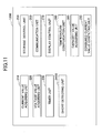
- FIG. 11 is a block diagram showing the functional composition of a short detection IC 120B of the third embodiment.
- the short detection IC 120B of this embodiment further includes a consumed current value computing unit 290.
- the short detecting unit 240B of this embodiment is arranged to detect an internal short-circuit in the battery unit 111 based on a current value computed from a discharge capacity value.
- the consumed current value computing unit 290 computes a consumed current value based on a capacity value acquired by the capacity value acquiring unit 285.
- FIG. 12 is a flowchart for explaining operation of the short detection IC 120B of the third embodiment.
- steps S1201 to S1209 are the same as the steps S901 to S909 shown in FIG. 9 , and a description thereof will be omitted.
- the current value computing unit 290 computes a consumed current value Ius during the predetermined period by using the capacity value Qus (S1210).
- the short detecting unit 240B determines whether the consumed current value Ius is larger than a predetermined value (S1211). When it is determined in step S1211 that the consumed current value Ius is larger than the predetermined value, the short detecting unit 240B determines that an internal short-circuit in the battery unit 111 takes place. In this case, the short detecting unit 240B notifies the communication unit 260 of the occurrence of an internal short-circuit in the battery unit 111. The communication unit 260 outputs a notice of internal short detection to the portable device (S1212).
- step S1211 which is a reference consumed current value used for internal short detection is stored beforehand in the ROM 123.
- a consumed current value is computed based on the discharge capacity value during the predetermined period, and the detection of an internal short-circuit in the battery unit can be detected.
- the detection of an internal short-circuit is based on the discharge capacity value, and it is possible to detect an internal short-circuit in the battery unit more accurately.
Landscapes
- Engineering & Computer Science (AREA)
- Manufacturing & Machinery (AREA)
- Chemical & Material Sciences (AREA)
- Chemical Kinetics & Catalysis (AREA)
- Electrochemistry (AREA)
- General Chemical & Material Sciences (AREA)
- Physics & Mathematics (AREA)
- General Physics & Mathematics (AREA)
- Protection Of Static Devices (AREA)
- Secondary Cells (AREA)
Applications Claiming Priority (2)
| Application Number | Priority Date | Filing Date | Title |
|---|---|---|---|
| JP2007326459 | 2007-12-18 | ||
| JP2008154519A JP2009170397A (ja) | 2007-12-18 | 2008-06-12 | 電池パック、電池パックを用いる携帯機器、電池パックにおける内部ショート検出方法、内部ショート検出プログラム |
Publications (1)
| Publication Number | Publication Date |
|---|---|
| EP2073031A2 true EP2073031A2 (fr) | 2009-06-24 |
Family
ID=40418940
Family Applications (1)
| Application Number | Title | Priority Date | Filing Date |
|---|---|---|---|
| EP08171862A Withdrawn EP2073031A2 (fr) | 2007-12-18 | 2008-12-16 | Bloc-batterie, dispositif portable, procédé de détection de court-circuit interne et programme de détection de court-circuit interne |
Country Status (2)
| Country | Link |
|---|---|
| US (2) | US20090155674A1 (fr) |
| EP (1) | EP2073031A2 (fr) |
Cited By (6)
| Publication number | Priority date | Publication date | Assignee | Title |
|---|---|---|---|---|
| CN106154172A (zh) * | 2016-06-17 | 2016-11-23 | 清华大学 | 锂离子动力电池内短路程度的定量估算方法 |
| EP3109653A1 (fr) * | 2015-06-23 | 2016-12-28 | Robert Bosch Gmbh | Procede de reconnaissance d'un court-circuit dans un accumulateur d'energie |
| EP3291353A1 (fr) * | 2016-09-02 | 2018-03-07 | Quanta Computer Inc. | Dispositif de batterie, dispositif électronique et procédé de protection d'un dispositif de batterie |
| EP3611817A1 (fr) * | 2018-08-13 | 2020-02-19 | Samsung SDI Co., Ltd. | Appareil et procédé de commande de batterie |
| KR20200019083A (ko) * | 2018-08-13 | 2020-02-21 | 삼성에스디아이 주식회사 | 배터리 제어 장치 및 배터리의 내부단락 검출 방법 |
| CN111699603A (zh) * | 2018-02-05 | 2020-09-22 | 三星Sdi株式会社 | 电池保护电路和包括该电池保护电路的电池组 |
Families Citing this family (28)
| Publication number | Priority date | Publication date | Assignee | Title |
|---|---|---|---|---|
| EP2485313B1 (fr) | 2009-09-30 | 2021-11-24 | Dai Nippon Printing Co., Ltd. | Appareil de contrôle de rupture d'isolation, procédé de contrôle de rupture d'isolation l'utilisant et procédé de fabrication d'une cellule électrochimique |
| US9678163B2 (en) | 2011-01-18 | 2017-06-13 | Tiax Llc | Differential current monitoring for parallel-connected batteries |
| TWI477788B (zh) * | 2012-04-10 | 2015-03-21 | Realtek Semiconductor Corp | 偵測發光二極體短路的方法及其裝置 |
| DE102013216972A1 (de) * | 2013-08-27 | 2015-03-05 | Volkswagen Aktiengesellschaft | Verfahren und Vorrichtung zur Überwachung einer elektrochemischen Zelle |
| DE102013220760A1 (de) * | 2013-10-15 | 2015-04-16 | Robert Bosch Gmbh | Kurzschlussdetektionsvorrichtung zur Detektion von Kurzschlüssen einer Batteriezelle und Verfahren zur Kurzschlussdetektion |
| EP3107182A4 (fr) * | 2014-02-07 | 2018-01-24 | Nec Corporation | Dispositif de correction de différence de tension, procédé de correction de différence de tension |
| CN112838286A (zh) * | 2014-06-30 | 2021-05-25 | 赛尔格有限责任公司 | 电池中区分短路的系统和方法 |
| KR102247052B1 (ko) | 2014-07-21 | 2021-04-30 | 삼성전자주식회사 | 배터리의 이상 상태를 감지하는 장치 및 방법 |
| KR102356475B1 (ko) | 2015-02-06 | 2022-01-27 | 삼성전자주식회사 | 배터리의 충전 전압 데이터에 기반한 배터리 상태 추정 방법 및 장치 |
| JP6876994B2 (ja) | 2016-06-16 | 2021-05-26 | パナソニックIpマネジメント株式会社 | 管理装置、及び蓄電システム |
| CN106230083B (zh) * | 2016-08-22 | 2018-12-04 | 维沃移动通信有限公司 | 充电器充电电路、移动终端充电电路、充电器及移动终端 |
| WO2018043222A1 (fr) | 2016-08-30 | 2018-03-08 | パナソニックIpマネジメント株式会社 | Dispositif de gestion et système de stockage d'énergie |
| US10656215B2 (en) | 2016-11-07 | 2020-05-19 | Nissan Motor Co., Ltd. | Short circuit detection device |
| KR102439932B1 (ko) | 2017-07-26 | 2022-09-05 | 삼성전자주식회사 | 배터리 이상 검출 방법 및 장치 |
| EP3657591B1 (fr) * | 2017-08-25 | 2021-07-14 | Guangdong Oppo Mobile Telecommunications Corp., Ltd. | Dispositif terminal et procédé et système de surveillance de sécurité de batterie associés |
| CN111108403A (zh) | 2017-09-21 | 2020-05-05 | 古河电气工业株式会社 | 可充电电池短路预测装置和可充电电池短路预测方法 |
| CN111263999A (zh) * | 2017-11-02 | 2020-06-09 | 株式会社杰士汤浅国际 | 管理装置、蓄电装置、原因的解析方法、发动机驱动车、电动汽车 |
| TWI657639B (zh) * | 2017-12-04 | 2019-04-21 | Industrial Technology Research Institute | 電池放電流程決定方法和系統 |
| US10838016B2 (en) * | 2018-07-06 | 2020-11-17 | Texas Instruments Incorporated | Short detect scheme for an output pin |
| US11035904B2 (en) | 2018-07-23 | 2021-06-15 | Samsung Sdi Co., Ltd. | Battery control apparatus and method for detecting internal short of battery |
| CN110154824B (zh) * | 2019-05-28 | 2021-04-20 | 蜂巢能源科技有限公司 | 电池包休眠的检测装置、方法及车辆 |
| US11186198B2 (en) * | 2019-05-31 | 2021-11-30 | Ford Global Technologies, Llc | Methods and systems for vehicle battery cell failure detection and overcharge protection |
| JP2020201081A (ja) * | 2019-06-07 | 2020-12-17 | 本田技研工業株式会社 | リチウムイオン二次電池の微小短絡判定方法 |
| DE102019134510A1 (de) * | 2019-12-16 | 2021-06-17 | Preh Gmbh | Verfahren zur Bestimmung eines bevorstehenden Fehlerfalls einer Batteriezelle sowie Batterie-Management-System |
| KR102332444B1 (ko) | 2019-12-23 | 2021-11-26 | 삼성에스디아이 주식회사 | 열 폭주 검출 장치, 배터리 시스템 및 배터리 시스템의 열 폭주 검출 방법 |
| US12241943B2 (en) * | 2021-07-14 | 2025-03-04 | GM Global Technology Operations LLC | Method for early detection of an internal short in a battery pack |
| JP2023136721A (ja) * | 2022-03-17 | 2023-09-29 | 株式会社東芝 | 充電制御方法、充電制御装置及び電池搭載機器 |
| EP4553508A3 (fr) | 2022-05-26 | 2025-08-20 | LG Energy Solution, Ltd. | Appareil et procédé de diagnostic d'élément de batterie |
Citations (1)
| Publication number | Priority date | Publication date | Assignee | Title |
|---|---|---|---|---|
| JP2006092850A (ja) | 2004-09-22 | 2006-04-06 | Matsushita Electric Ind Co Ltd | 電池パック |
Family Cites Families (1)
| Publication number | Priority date | Publication date | Assignee | Title |
|---|---|---|---|---|
| JP4739040B2 (ja) * | 2005-02-18 | 2011-08-03 | パナソニック株式会社 | 二次電池の内部短絡検出装置、二次電池の内部短絡検出方法、二次電池の電池パック及び電子機器 |
-
2008
- 2008-12-12 US US12/333,697 patent/US20090155674A1/en not_active Abandoned
- 2008-12-16 EP EP08171862A patent/EP2073031A2/fr not_active Withdrawn
-
2014
- 2014-03-04 US US14/196,101 patent/US20140184235A1/en not_active Abandoned
Patent Citations (1)
| Publication number | Priority date | Publication date | Assignee | Title |
|---|---|---|---|---|
| JP2006092850A (ja) | 2004-09-22 | 2006-04-06 | Matsushita Electric Ind Co Ltd | 電池パック |
Cited By (13)
| Publication number | Priority date | Publication date | Assignee | Title |
|---|---|---|---|---|
| EP3109653A1 (fr) * | 2015-06-23 | 2016-12-28 | Robert Bosch Gmbh | Procede de reconnaissance d'un court-circuit dans un accumulateur d'energie |
| US10365312B2 (en) | 2015-06-23 | 2019-07-30 | Robert Bosch Gmbh | Method for detection of short circuits within an energy storage device |
| CN106154172B (zh) * | 2016-06-17 | 2018-11-23 | 清华大学 | 锂离子动力电池内短路程度的定量估算方法 |
| CN106154172A (zh) * | 2016-06-17 | 2016-11-23 | 清华大学 | 锂离子动力电池内短路程度的定量估算方法 |
| EP3291353A1 (fr) * | 2016-09-02 | 2018-03-07 | Quanta Computer Inc. | Dispositif de batterie, dispositif électronique et procédé de protection d'un dispositif de batterie |
| US10547185B2 (en) | 2016-09-02 | 2020-01-28 | Quanta Computer Inc. | Battery device, electronic device and method for protecting a battery device |
| EP3751693A4 (fr) * | 2018-02-05 | 2021-11-03 | Samsung SDI Co., Ltd. | Circuit de protection de batterie et bloc-batterie comprenant celui-ci |
| CN111699603B (zh) * | 2018-02-05 | 2023-08-04 | 三星Sdi株式会社 | 电池保护电路和包括该电池保护电路的电池组 |
| CN111699603A (zh) * | 2018-02-05 | 2020-09-22 | 三星Sdi株式会社 | 电池保护电路和包括该电池保护电路的电池组 |
| EP3611817A1 (fr) * | 2018-08-13 | 2020-02-19 | Samsung SDI Co., Ltd. | Appareil et procédé de commande de batterie |
| US11041914B2 (en) | 2018-08-13 | 2021-06-22 | Samsung Sdi Co., Ltd. | Battery control apparatus and method for detection internal short of battery |
| KR102238559B1 (ko) | 2018-08-13 | 2021-04-09 | 삼성에스디아이 주식회사 | 배터리 제어 장치 및 배터리의 내부단락 검출 방법 |
| KR20200019083A (ko) * | 2018-08-13 | 2020-02-21 | 삼성에스디아이 주식회사 | 배터리 제어 장치 및 배터리의 내부단락 검출 방법 |
Also Published As
| Publication number | Publication date |
|---|---|
| US20140184235A1 (en) | 2014-07-03 |
| US20090155674A1 (en) | 2009-06-18 |
Similar Documents
| Publication | Publication Date | Title |
|---|---|---|
| EP2073031A2 (fr) | Bloc-batterie, dispositif portable, procédé de détection de court-circuit interne et programme de détection de court-circuit interne | |
| CN101465449B (zh) | 电池组、便携设备、电池组的内部短路检测方法和程序 | |
| US7977916B2 (en) | Battery pack | |
| EP2333929A1 (fr) | Dispositif mobile, bloc-batterie, procédé de commande d'affichage, et programme de commande d'affichage | |
| CN101465557B (zh) | 便携式设备、用于便携式设备的电池盒 | |
| US7723949B2 (en) | Battery device | |
| US7382110B2 (en) | Method of charging secondary battery, method of calculating remaining capacity rate of secondary battery, and battery pack | |
| JP2010186619A (ja) | 電池パックおよび電池容量計算方法 | |
| CN102782977B (zh) | 保护监视电路和电池组 | |
| JP3925507B2 (ja) | 二次電池の充電方法および電池パック | |
| WO2010082549A1 (fr) | Bloc-batterie, circuit intégré à semi-conducteurs, procédé de correction de capacité restante, et milieu de stockage | |
| US9774062B2 (en) | Storage battery, control method of storage battery, control device, and control method | |
| US6972545B2 (en) | Battery pack and battery remaining power calculating method | |
| JP2009097954A (ja) | 電池パックおよび二次電池の残容量補正方法 | |
| JP2009133676A (ja) | 電池パックおよび充放電方法 | |
| JP5601214B2 (ja) | 電池容量補正装置及び電池容量補正方法 | |
| JP4086008B2 (ja) | 二次電池の残容量率算出方法および電池パック | |
| CN108072793B (zh) | 用于计算电池系统的线路电阻的方法和设备 | |
| EP4242677B1 (fr) | Solution mère de jauge universelle dans un système à plusieurs batteries | |
| KR20030010867A (ko) | 휴대폰의 스마트 배터리 | |
| HK1072469A1 (zh) | 電池組及電池剩餘電量計算方法 | |
| HK1072469B (en) | Battery pack and remaining battery power calculation method | |
| JPH11339857A (ja) | 二次電池の放電管理装置 |
Legal Events
| Date | Code | Title | Description |
|---|---|---|---|
| PUAI | Public reference made under article 153(3) epc to a published international application that has entered the european phase |
Free format text: ORIGINAL CODE: 0009012 |
|
| AK | Designated contracting states |
Kind code of ref document: A2 Designated state(s): AT BE BG CH CY CZ DE DK EE ES FI FR GB GR HR HU IE IS IT LI LT LU LV MC MT NL NO PL PT RO SE SI SK TR |
|
| AX | Request for extension of the european patent |
Extension state: AL BA MK RS |
|
| STAA | Information on the status of an ep patent application or granted ep patent |
Free format text: STATUS: THE APPLICATION HAS BEEN WITHDRAWN |
|
| 18W | Application withdrawn |
Effective date: 20121224 |