WO2018043222A1 - Dispositif de gestion et système de stockage d'énergie - Google Patents
Dispositif de gestion et système de stockage d'énergie Download PDFInfo
- Publication number
- WO2018043222A1 WO2018043222A1 PCT/JP2017/030020 JP2017030020W WO2018043222A1 WO 2018043222 A1 WO2018043222 A1 WO 2018043222A1 JP 2017030020 W JP2017030020 W JP 2017030020W WO 2018043222 A1 WO2018043222 A1 WO 2018043222A1
- Authority
- WO
- WIPO (PCT)
- Prior art keywords
- power storage
- voltage
- smoothing
- blocks
- difference
- Prior art date
- Legal status (The legal status is an assumption and is not a legal conclusion. Google has not performed a legal analysis and makes no representation as to the accuracy of the status listed.)
- Ceased
Links
Images


Classifications
-
- G—PHYSICS
- G01—MEASURING; TESTING
- G01R—MEASURING ELECTRIC VARIABLES; MEASURING MAGNETIC VARIABLES
- G01R31/00—Arrangements for testing electric properties; Arrangements for locating electric faults; Arrangements for electrical testing characterised by what is being tested not provided for elsewhere
- G01R31/36—Arrangements for testing, measuring or monitoring the electrical condition of accumulators or electric batteries, e.g. capacity or state of charge [SoC]
- G01R31/382—Arrangements for monitoring battery or accumulator variables, e.g. SoC
- G01R31/3835—Arrangements for monitoring battery or accumulator variables, e.g. SoC involving only voltage measurements
-
- G—PHYSICS
- G01—MEASURING; TESTING
- G01R—MEASURING ELECTRIC VARIABLES; MEASURING MAGNETIC VARIABLES
- G01R31/00—Arrangements for testing electric properties; Arrangements for locating electric faults; Arrangements for electrical testing characterised by what is being tested not provided for elsewhere
- G01R31/36—Arrangements for testing, measuring or monitoring the electrical condition of accumulators or electric batteries, e.g. capacity or state of charge [SoC]
- G01R31/392—Determining battery ageing or deterioration, e.g. state of health
-
- G—PHYSICS
- G01—MEASURING; TESTING
- G01R—MEASURING ELECTRIC VARIABLES; MEASURING MAGNETIC VARIABLES
- G01R31/00—Arrangements for testing electric properties; Arrangements for locating electric faults; Arrangements for electrical testing characterised by what is being tested not provided for elsewhere
- G01R31/36—Arrangements for testing, measuring or monitoring the electrical condition of accumulators or electric batteries, e.g. capacity or state of charge [SoC]
- G01R31/396—Acquisition or processing of data for testing or for monitoring individual cells or groups of cells within a battery
-
- H—ELECTRICITY
- H01—ELECTRIC ELEMENTS
- H01M—PROCESSES OR MEANS, e.g. BATTERIES, FOR THE DIRECT CONVERSION OF CHEMICAL ENERGY INTO ELECTRICAL ENERGY
- H01M10/00—Secondary cells; Manufacture thereof
- H01M10/42—Methods or arrangements for servicing or maintenance of secondary cells or secondary half-cells
- H01M10/425—Structural combination with electronic components, e.g. electronic circuits integrated to the outside of the casing
-
- H—ELECTRICITY
- H01—ELECTRIC ELEMENTS
- H01M—PROCESSES OR MEANS, e.g. BATTERIES, FOR THE DIRECT CONVERSION OF CHEMICAL ENERGY INTO ELECTRICAL ENERGY
- H01M10/00—Secondary cells; Manufacture thereof
- H01M10/42—Methods or arrangements for servicing or maintenance of secondary cells or secondary half-cells
- H01M10/44—Methods for charging or discharging
-
- H—ELECTRICITY
- H01—ELECTRIC ELEMENTS
- H01M—PROCESSES OR MEANS, e.g. BATTERIES, FOR THE DIRECT CONVERSION OF CHEMICAL ENERGY INTO ELECTRICAL ENERGY
- H01M10/00—Secondary cells; Manufacture thereof
- H01M10/42—Methods or arrangements for servicing or maintenance of secondary cells or secondary half-cells
- H01M10/48—Accumulators combined with arrangements for measuring, testing or indicating the condition of cells, e.g. the level or density of the electrolyte
-
- H—ELECTRICITY
- H01—ELECTRIC ELEMENTS
- H01M—PROCESSES OR MEANS, e.g. BATTERIES, FOR THE DIRECT CONVERSION OF CHEMICAL ENERGY INTO ELECTRICAL ENERGY
- H01M50/00—Constructional details or processes of manufacture of the non-active parts of electrochemical cells other than fuel cells, e.g. hybrid cells
- H01M50/20—Mountings; Secondary casings or frames; Racks, modules or packs; Suspension devices; Shock absorbers; Transport or carrying devices; Holders
- H01M50/204—Racks, modules or packs for multiple batteries or multiple cells
-
- H—ELECTRICITY
- H02—GENERATION; CONVERSION OR DISTRIBUTION OF ELECTRIC POWER
- H02H—EMERGENCY PROTECTIVE CIRCUIT ARRANGEMENTS
- H02H7/00—Emergency protective circuit arrangements specially adapted for specific types of electric machines or apparatus or for sectionalised protection of cable or line systems, and effecting automatic switching in the event of an undesired change from normal working conditions
- H02H7/18—Emergency protective circuit arrangements specially adapted for specific types of electric machines or apparatus or for sectionalised protection of cable or line systems, and effecting automatic switching in the event of an undesired change from normal working conditions for batteries; for accumulators
-
- H—ELECTRICITY
- H02—GENERATION; CONVERSION OR DISTRIBUTION OF ELECTRIC POWER
- H02J—ELECTRIC POWER NETWORKS; CIRCUIT ARRANGEMENTS OR SYSTEMS FOR SUPPLYING OR DISTRIBUTING ELECTRIC POWER; SYSTEMS FOR STORING ELECTRIC ENERGY
- H02J7/00—Circuit arrangements for charging or discharging batteries or for supplying loads from batteries
-
- H—ELECTRICITY
- H02—GENERATION; CONVERSION OR DISTRIBUTION OF ELECTRIC POWER
- H02J—ELECTRIC POWER NETWORKS; CIRCUIT ARRANGEMENTS OR SYSTEMS FOR SUPPLYING OR DISTRIBUTING ELECTRIC POWER; SYSTEMS FOR STORING ELECTRIC ENERGY
- H02J7/00—Circuit arrangements for charging or discharging batteries or for supplying loads from batteries
- H02J7/50—Circuit arrangements for charging or discharging batteries or for supplying loads from batteries acting upon multiple batteries simultaneously or sequentially
-
- H—ELECTRICITY
- H02—GENERATION; CONVERSION OR DISTRIBUTION OF ELECTRIC POWER
- H02J—ELECTRIC POWER NETWORKS; CIRCUIT ARRANGEMENTS OR SYSTEMS FOR SUPPLYING OR DISTRIBUTING ELECTRIC POWER; SYSTEMS FOR STORING ELECTRIC ENERGY
- H02J7/00—Circuit arrangements for charging or discharging batteries or for supplying loads from batteries
- H02J7/80—Circuit arrangements for charging or discharging batteries or for supplying loads from batteries including monitoring or indicating arrangements
- H02J7/82—Control of state of charge [SOC]
-
- H—ELECTRICITY
- H01—ELECTRIC ELEMENTS
- H01M—PROCESSES OR MEANS, e.g. BATTERIES, FOR THE DIRECT CONVERSION OF CHEMICAL ENERGY INTO ELECTRICAL ENERGY
- H01M10/00—Secondary cells; Manufacture thereof
- H01M10/42—Methods or arrangements for servicing or maintenance of secondary cells or secondary half-cells
- H01M10/425—Structural combination with electronic components, e.g. electronic circuits integrated to the outside of the casing
- H01M2010/4271—Battery management systems including electronic circuits, e.g. control of current or voltage to keep battery in healthy state, cell balancing
-
- H—ELECTRICITY
- H01—ELECTRIC ELEMENTS
- H01M—PROCESSES OR MEANS, e.g. BATTERIES, FOR THE DIRECT CONVERSION OF CHEMICAL ENERGY INTO ELECTRICAL ENERGY
- H01M10/00—Secondary cells; Manufacture thereof
- H01M10/42—Methods or arrangements for servicing or maintenance of secondary cells or secondary half-cells
- H01M10/425—Structural combination with electronic components, e.g. electronic circuits integrated to the outside of the casing
- H01M2010/4278—Systems for data transfer from batteries, e.g. transfer of battery parameters to a controller, data transferred between battery controller and main controller
-
- H—ELECTRICITY
- H02—GENERATION; CONVERSION OR DISTRIBUTION OF ELECTRIC POWER
- H02J—ELECTRIC POWER NETWORKS; CIRCUIT ARRANGEMENTS OR SYSTEMS FOR SUPPLYING OR DISTRIBUTING ELECTRIC POWER; SYSTEMS FOR STORING ELECTRIC ENERGY
- H02J2105/00—Networks for supplying or distributing electric power characterised by their spatial reach or by the load
- H02J2105/30—Networks for supplying or distributing electric power characterised by their spatial reach or by the load the load networks being external to vehicles, i.e. exchanging power with vehicles
-
- Y—GENERAL TAGGING OF NEW TECHNOLOGICAL DEVELOPMENTS; GENERAL TAGGING OF CROSS-SECTIONAL TECHNOLOGIES SPANNING OVER SEVERAL SECTIONS OF THE IPC; TECHNICAL SUBJECTS COVERED BY FORMER USPC CROSS-REFERENCE ART COLLECTIONS [XRACs] AND DIGESTS
- Y02—TECHNOLOGIES OR APPLICATIONS FOR MITIGATION OR ADAPTATION AGAINST CLIMATE CHANGE
- Y02E—REDUCTION OF GREENHOUSE GAS [GHG] EMISSIONS, RELATED TO ENERGY GENERATION, TRANSMISSION OR DISTRIBUTION
- Y02E60/00—Enabling technologies; Technologies with a potential or indirect contribution to GHG emissions mitigation
- Y02E60/10—Energy storage using batteries
-
- Y—GENERAL TAGGING OF NEW TECHNOLOGICAL DEVELOPMENTS; GENERAL TAGGING OF CROSS-SECTIONAL TECHNOLOGIES SPANNING OVER SEVERAL SECTIONS OF THE IPC; TECHNICAL SUBJECTS COVERED BY FORMER USPC CROSS-REFERENCE ART COLLECTIONS [XRACs] AND DIGESTS
- Y02—TECHNOLOGIES OR APPLICATIONS FOR MITIGATION OR ADAPTATION AGAINST CLIMATE CHANGE
- Y02T—CLIMATE CHANGE MITIGATION TECHNOLOGIES RELATED TO TRANSPORTATION
- Y02T10/00—Road transport of goods or passengers
- Y02T10/60—Other road transportation technologies with climate change mitigation effect
- Y02T10/70—Energy storage systems for electromobility, e.g. batteries
Definitions
- the present invention relates to a management device for managing a power storage unit, and a power storage system.
- secondary batteries such as lithium ion batteries and nickel metal hydride batteries have been used for various purposes.
- in-vehicle applications including electric bicycles, peak shifts, and backups for supplying electric power to EV (Electric Vehicle), HEV (Hybrid Electric Vehicle), and PHV (Plug-in Hybrid Vehicle) driving motors Is used for power storage purposes, and for FR (Frequency Regulation) purposes for frequency stabilization of the system.
- a minute short circuit may occur in the battery due to contact between the positive electrode and the negative electrode due to a shift of the separator, or generation of a conductive path due to contamination of the battery.
- the micro short-circuit causes overheating, and may shift from the micro short-circuit state to a complete short-circuit state due to a change in the direction of foreign matter.
- a micro short circuit is generally detected based on a change in cell voltage or SOC (State Of Of Charge) during a period in which charging / discharging is stopped (see, for example, Patent Document 1).
- SOC State Of Of Charge
- a micro short circuit occurs, a conductive path is formed between the positive electrode and the negative electrode of the battery. Therefore, in the battery in which the micro short circuit occurs, a current flows even while charging / discharging is stopped, and the voltage and SOC decrease.
- There has also been proposed a method of detecting a micro short circuit based on the rate of increase of the cell voltage while charging or the rate of decrease of the cell voltage while continuing discharge see, for example, Patent Document 2.
- Some power storage systems used for FR continue to charge and discharge for 24 hours.
- discharge from a power storage system to a commercial power system (hereinafter simply referred to as a system) and charging from the system to the power storage system occur irregularly according to the frequency or voltage of the system.
- a system a commercial power system
- the present invention has been made in view of such circumstances, and an object of the present invention is to provide a technique for detecting a cell abnormality without considering a current state.
- a management device includes m (m is an integer of 1 or more) storage cells and n (n is an integer of 2 or more) storage blocks connected in parallel.
- the difference between the smoothing unit for smoothing and the smoothing voltage of one of the n storage blocks and the smoothing voltage of the remaining storage block or all of the storage blocks is calculated.
- a determination unit that determines that a power storage block whose difference between the representative value and the representative value is greater than or equal to a set value in a predetermined period is a power storage block including an abnormal power storage cell.
- cell abnormality can be detected without considering the current state.
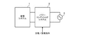
- FIG. 1 is a diagram for explaining a usage example of a power storage system 1 according to an embodiment of the present invention.
- the power storage system 1 shown in FIG. 1 is used for FR, and is connected to the system 3 through a power conditioner system 2.
- the power conditioner system 2 includes a bidirectional inverter. When the power storage system 1 is discharged, the DC power supplied from the power storage system 1 is converted into AC power and supplied to the system 3. In addition, when the power storage system 1 is charged, AC power supplied from the grid 3 is converted into DC power and supplied to the power storage system 1.
- An electric power supplier such as an electric power company needs to stably supply electric power, and it is necessary to keep the frequency and voltage of the grid 3 within a certain range.
- the power storage system 1 is used as a means for system stabilization.
- independent system operators ISO: Independend System Operators
- RTO Regional Transmission Organization
- the ISO or RTO notifies the power conditioner system 2 of the power storage system 1 procured by bidding to notify the power command every several seconds and suppress fluctuations in the system frequency. Specifically, a discharge command is notified when the system frequency decreases, and a charge command is notified when the system frequency increases.
- FIG. 2 is a diagram showing a configuration example of the power storage system 1 according to the embodiment of the present invention.
- the power storage system 1 includes a power storage module 20 and a battery management device 10.
- the power storage module 20 is configured by connecting n (n is an integer of 2 or more) battery blocks (first battery block B1, second battery block B2,..., Nth battery block Bn) in series.
- the first battery block B1 is configured by connecting m (m is an integer of 1 or more) battery cells S11-S1m in parallel. The same applies to the second battery block B2 and the nth battery block Bn.
- As the battery cell a lithium ion battery cell, a nickel metal hydride battery cell, a lead battery cell, or the like can be used.
- FIG. 2 one power storage module 20 is illustrated, but a plurality of power storage modules can be further connected in series to increase the output voltage.
- the battery management device 10 includes a voltage detection unit 11, a control unit 13, and a storage unit 14.
- the voltage detection unit 11 detects the detection voltage of each of the battery blocks B1, B2,..., Bn at a predetermined sampling cycle (for example, 1 second cycle), and outputs it to the control unit 13.
- the control unit 13 includes a smoothing unit 13a, a calculation unit 13b, and a determination unit 13c.
- the configuration of the control unit 13 can be realized by cooperation of hardware resources and software resources, or only by hardware resources.
- a hardware resource a microcomputer, DSP, FPGA, or other LSI can be used.
- Firmware and other programs can be used as software resources.
- the storage unit 14 can be realized by a ROM and a RAM, and is used as a work area for the smoothing unit 13a, the calculation unit 13b, and the determination unit 13c in the present embodiment.
- the smoothing unit 13a also stores the past data of the battery blocks B1, B2,..., Bn detected by the voltage detection unit 11 over a certain period (for example, 10 hours, 12 hours, 24 hours). And smoothing voltage is generated.
- the smoothing unit 13a smoothes the voltages of the battery blocks B1, B2,..., Bn using, for example, a primary low-pass filter of the following (Equation 1).
- V ⁇ (t) ⁇ V (t) + (1- ⁇ ) V ⁇ (t-1) (Equation 1) 0 ⁇ ⁇ 1
- Equation 1 0 ⁇ ⁇ 1
- Equation 1 is an example of the smoothing process, and other smoothing processes may be used.
- a smoothing voltage may be generated by calculating a moving average of detection voltages for a certain period.
- the calculation unit 13b calculates a representative value of the smoothing voltages of the remaining battery blocks excluding the smoothing voltage of the target battery block among the smoothing voltages of the n battery blocks B1, B2, ..., Bn. .
- the median value of the smoothed voltages of the remaining battery blocks is calculated as a representative value.
- the calculation unit 13b calculates a difference between the smoothed voltage of the target battery block and the representative value of the smoothed voltages of the remaining battery blocks.
- the determination unit 13c determines that the target battery block is a battery block including a battery cell that is slightly short-circuited when the difference is increased by a predetermined value or more in a predetermined period. For example, when the difference expands by 5 mV or more in 12 hours, it is determined that the battery block includes a battery cell that is slightly short-circuited.
- the criterion depends on the battery specifications and the number of parallel connections. As the battery capacity and / or the parallel number increases, the influence of the discharge due to the micro short circuit is reduced, and therefore, the gradient of the difference change with respect to the determination time serving as a determination criterion is set to be gentle. Conversely, as the battery capacity and / or the parallel number is smaller, the gradient of the difference change with respect to the determination time serving as a determination reference is set more rapidly.
- FIG. 3 is a diagram showing an example of occurrence of abnormality in the battery cell.
- a state in which the first battery block B1 and the second battery block B2 are connected in series as illustrated in FIG. 3 will be described as an example.
- each battery cell constituting each battery block has an internal resistance R11-Rnm.
- the voltage drop of the second battery block B2 is larger than the voltage drop of the first battery block B1.
- FIG. 4 is a flowchart showing the flow of the micro short-circuit detection method by the battery management apparatus 10 according to the embodiment of the present invention.
- 1 is set to the variable i (S10).
- the voltage detector 11 detects the voltages of n battery blocks (S11).
- the smoothing unit 13a smoothes the voltage of each battery block to generate a smoothed voltage (S12).
- the calculating unit 13b calculates the median value of the smoothed voltages of the remaining battery blocks excluding the battery block (i) (S13).
- the calculation unit 13b calculates the difference (i) by subtracting the smoothed voltage of the battery block (i) from the calculated median value (S14).
- the calculation unit 13b calculates a change value ⁇ V of the difference (i) by subtracting the difference (i) calculated before a predetermined period from the currently calculated difference (i) (S15).
- the determination unit 13c determines whether or not the change value ⁇ V of the difference (i) is greater than or equal to a set value (S16).
- the set value is set to a value derived by the designer based on experimental data or simulation data such as the battery specification, the number of parallel connections, and the current that flows when a minute short circuit occurs in the battery.
- the determination unit 13c determines that the battery block (i) includes a battery cell that is slightly short-circuited (S17). The determination unit 13c notifies the host device (in this embodiment, the power conditioner system 2) of the occurrence of a micro short circuit.
- the process in step S17 is skipped.
- the variable i is incremented (S18), and it is determined whether the variable i exceeds the serial number n (S19).
- the process proceeds to step S13, and the determination process of the minute short circuit of the other battery block is continued.
- the process proceeds to step S10 (N in S21), and a new voltage is detected.
- the power source of the battery management device 10 is turned off (Y in S21)
- the micro short-circuit detection process ends.
- the power-off determination condition is described in step S ⁇ b> 21, but when the power of the battery management device 10 is turned off, the micro short-circuit detection process ends at any time.
- the influence of the status (charge, discharge, stop) at the time of voltage detection can be removed by using the smoothed voltage obtained by smoothing the voltage for a certain period. Therefore, a minute short circuit of the battery cell can be detected regardless of the current state. That is, there is no need to separate charging and discharging, and it is possible to uniformly determine the presence or absence of a micro short circuit without being restricted by the current value. Since it is not restricted by the current value, it can be applied to applications where charging and discharging are always performed. Further, by using a smoothing voltage whose fluctuation is smaller than that of the detection voltage, it can be applied to applications such as FR in which fluctuations in charging and discharging vary irregularly and drastically. The same algorithm can be applied not only to FR applications but also to in-vehicle applications and stationary applications, and is highly versatile.
- the feature amount (the amount of change in the smoothing voltage) used in the present embodiment is changed at an early stage when a minute short circuit occurs, and thus can be detected in a short time.
- the feature amount (the amount of change in the smoothing voltage) used in the present embodiment is changed at an early stage when a minute short circuit occurs, and thus can be detected in a short time.
- it takes time to detect since the voltage of the battery block varies due to temperature, deterioration, etc., it takes time to determine that a difference in the voltage of the battery block has occurred due to a minute short circuit.
- the presence / absence of a micro short circuit of the battery cell included in the target battery block is determined.
- the representative values of the smoothed SOC of the target battery block and the smoothed SOC of the remaining battery blocks may be determined.
- the SOC of each battery block can be estimated by the OCV (Open Circuit Voltage) method. There is a stable relationship between the open circuit voltage of the battery and the SOC, and the SOC can be estimated by detecting the open circuit voltage.
- the SOC can also be calculated by a current integration method, but the position of the battery block in which a micro short-circuit has occurred among the battery blocks connected in series cannot be specified from the detected current value.
- the smoothing voltage / SOC of the target battery block by comparing the smoothing voltage / SOC of the target battery block with the representative values of the smoothing voltage / SOC of the remaining battery blocks, the presence or absence of a micro short circuit of the battery cells included in the target battery block was judged.
- the smoothing voltage / SOC of the target battery block by comparing the smoothing voltage / SOC of the target battery block with the representative values of the smoothing voltage / SOC of all the battery blocks, it is determined whether there is a micro short circuit in the battery cell included in the target battery block. Also good.
- the difference between the two can be increased.
- the smoothing voltage / SOC of the target battery block is compared with the representative value of the smoothing voltage / SOC of all the battery blocks, the calculation amount can be reduced because the representative value needs to be calculated only once. .
- a battery block including one or more battery cells is used as a power storage module.
- one or more capacitor cells for example, an electric double layer capacitor cell, a lithium ion capacitor cell
- a power storage block including may be used.
- the above-described series of processing from the voltage / SOC smoothing processing of the target battery block to the determination processing for the presence or absence of micro short-circuits may be executed only when the voltage / SOC of the target battery block is within a predetermined range.
- a predetermined intermediate range for example, a voltage range corresponding to SOC 10% to 90%, more preferably a voltage range corresponding to SOC 30% to 70%
- the above process is executed, and the series of processes is interrupted when it is out of the range of the predetermined intermediate area. In a region where the SOC is low, the voltage change is significant and the smoothing accuracy may be reduced.
- the smoothing accuracy may decrease even in a region where the SOC is high. Therefore, by performing the above range restriction, it is possible to prevent the determination accuracy of the micro short circuit from being lowered.
- the charge / discharge control is performed so that the target battery block returns to the intermediate region, or the detection method of the micro short circuit is switched to another method.
- the smoothing period is set to be longer than 10 hours to increase the detection accuracy.
- the smoothing period is shortened to 1 to 2 hours, and when the current difference (i) is compared with the past difference (i), the past difference (i) that is traced back for a longer period of time is used.
- the detection accuracy may be increased.
- Power storage modules (S11-Snm), m (m is an integer of 1 or more), power storage blocks (B1-Bn) connected in parallel, n (n is an integer of 2 or more), power storage modules connected in series ( 20) a management device (10) for managing A voltage detector (11) for detecting each voltage of the n power storage blocks (B1-Bn); A smoothing unit (13a) for smoothing the detected voltage of each power storage block (B1-Bn) based on past data for a certain period; Of the n power storage blocks (B1-Bn), the smoothing voltage of one power storage block (B1) and the smoothing voltage of the remaining power storage blocks (B2-Bn) or all the power storage blocks (B1-Bn) A calculation unit (13b) for calculating a difference from the representative value of A determination unit (13c) that determines that the power storage block (B1) whose difference from the representative value is equal to or larger than a set value in a predetermined period is a power storage block (B
- the calculation unit (13b) calculates the difference between the smoothed voltage of one power storage block (B1) out of the n power storage blocks (B1-Bn) and the median value of the remaining power storage blocks (B2-Bn).
- Power storage modules (S11-Snm), m (m is an integer of 1 or more), power storage blocks (B1-Bn) connected in parallel, n (n is an integer of 2 or more), power storage modules connected in series ( 20) a management device (10) for managing A voltage detector (11) for detecting each voltage of the n power storage blocks (B1-Bn); A smoothing unit (13a) for smoothing the SOC based on the detected voltage of each power storage block (B1-Bn) based on past data for a certain period; Of the n power storage blocks (B1-Bn), the smoothed SOC of one power storage block (B1) and the smoothed SOC of the remaining power storage blocks (B2-Bn) or all the power storage blocks (B1-Bn) A calculation unit (13b) for calculating a difference from the representative value of A determination unit (13c) that determines that the power storage block (B1) whose difference from the representative value is equal to or larger than a set value in a pre
- the voltage of the power storage block (B1) falls within a predetermined range.
- the SOC of the power storage block (B1) falls within a predetermined range.
- 1 power storage system 1 power storage system, 2 power conditioner system, 3 systems, 10 battery management device, 11 voltage detection unit, 13 control unit, 13a smoothing unit, 13b calculation unit, 13c determination unit, 14 storage unit, 20 storage module, B1 1st 1 battery block, B2 2nd battery block, Bn nth battery block, S11 battery cell, R11 internal resistance, Ps fine short circuit path.
Landscapes
- Engineering & Computer Science (AREA)
- General Physics & Mathematics (AREA)
- Physics & Mathematics (AREA)
- Chemical & Material Sciences (AREA)
- Chemical Kinetics & Catalysis (AREA)
- Electrochemistry (AREA)
- General Chemical & Material Sciences (AREA)
- Power Engineering (AREA)
- Manufacturing & Machinery (AREA)
- Microelectronics & Electronic Packaging (AREA)
- Secondary Cells (AREA)
- Tests Of Electric Status Of Batteries (AREA)
- Protection Of Static Devices (AREA)
- Charge And Discharge Circuits For Batteries Or The Like (AREA)
Abstract
Selon la présente invention, une unité de lissage (13a) lisse la tension détectée de chaque bloc de stockage d'énergie sur la base de données passées pour une période fixe. Une unité de calcul (13b) calcule la différence entre la tension lissée d'un bloc de stockage d'énergie parmi n blocs de stockage d'énergie et une valeur représentative pour les tensions lissées des blocs de stockage d'énergie restants ou tous les blocs de stockage d'énergie. Une unité de détermination (13c) détermine qu'un bloc de stockage d'énergie pour lequel la différence avec la valeur représentative a été développée au moyen d'une valeur définie ou supérieure sur une période fixe constitue un bloc de stockage d'énergie qui comprend une cellule de stockage d'énergie anormale.
Priority Applications (3)
| Application Number | Priority Date | Filing Date | Title |
|---|---|---|---|
| JP2018537167A JP6986707B2 (ja) | 2016-08-30 | 2017-08-23 | 管理装置、及び蓄電システム |
| CN201780051078.8A CN109661588A (zh) | 2016-08-30 | 2017-08-23 | 管理装置以及蓄电系统 |
| US16/275,242 US10811889B2 (en) | 2016-08-30 | 2019-02-13 | Management device and power storage system |
Applications Claiming Priority (2)
| Application Number | Priority Date | Filing Date | Title |
|---|---|---|---|
| JP2016168510 | 2016-08-30 | ||
| JP2016-168510 | 2016-08-30 |
Related Child Applications (1)
| Application Number | Title | Priority Date | Filing Date |
|---|---|---|---|
| US16/275,242 Continuation US10811889B2 (en) | 2016-08-30 | 2019-02-13 | Management device and power storage system |
Publications (1)
| Publication Number | Publication Date |
|---|---|
| WO2018043222A1 true WO2018043222A1 (fr) | 2018-03-08 |
Family
ID=61305279
Family Applications (1)
| Application Number | Title | Priority Date | Filing Date |
|---|---|---|---|
| PCT/JP2017/030020 Ceased WO2018043222A1 (fr) | 2016-08-30 | 2017-08-23 | Dispositif de gestion et système de stockage d'énergie |
Country Status (4)
| Country | Link |
|---|---|
| US (1) | US10811889B2 (fr) |
| JP (1) | JP6986707B2 (fr) |
| CN (1) | CN109661588A (fr) |
| WO (1) | WO2018043222A1 (fr) |
Cited By (9)
| Publication number | Priority date | Publication date | Assignee | Title |
|---|---|---|---|---|
| WO2020021888A1 (fr) * | 2018-07-25 | 2020-01-30 | パナソニックIpマネジメント株式会社 | Dispositif de gestion et système d'alimentation électrique |
| WO2020021889A1 (fr) * | 2018-07-25 | 2020-01-30 | パナソニックIpマネジメント株式会社 | Dispositif de gestion et système d'alimentation électrique |
| JPWO2021033480A1 (fr) * | 2019-08-22 | 2021-02-25 | ||
| WO2021125676A1 (fr) * | 2019-12-20 | 2021-06-24 | 주식회사 엘지에너지솔루션 | Dispositif et procédé de diagnostic de batterie |
| JP2021173551A (ja) * | 2020-04-21 | 2021-11-01 | トヨタ自動車株式会社 | 組電池の状態判定装置および状態判定方法 |
| WO2023095674A1 (fr) * | 2021-11-29 | 2023-06-01 | パナソニックIpマネジメント株式会社 | Système de détection d'anomalie de batterie, procédé de détection d'anomalie de batterie et programme de détection d'anomalie de batterie |
| JP2024509220A (ja) * | 2021-03-12 | 2024-02-29 | ベバスト エスエー | 電池監視ユニット |
| JP2025530378A (ja) * | 2022-09-22 | 2025-09-11 | エルジー エナジー ソリューション リミテッド | 電池管理装置およびその動作方法 |
| US12613289B2 (en) | 2021-10-13 | 2026-04-28 | Lg Energy Solution, Ltd. | Battery diagnosis apparatus, battery pack, electric vehicle, and battery diagnosis method |
Families Citing this family (3)
| Publication number | Priority date | Publication date | Assignee | Title |
|---|---|---|---|---|
| WO2020026509A1 (fr) * | 2018-07-30 | 2020-02-06 | 日立オートモティブシステムズ株式会社 | Dispositif d'estimation d'état de cellule et dispositif de commande de cellule |
| CN113866669B (zh) | 2020-06-30 | 2023-09-15 | 宁德时代新能源科技股份有限公司 | 电芯内部短路故障的检测方法、装置、设备和介质 |
| EP4443692A4 (fr) * | 2021-11-30 | 2025-06-18 | Panasonic Intellectual Property Management Co., Ltd. | Système de détection d'anomalie de batterie, procédé de détection d'anomalie de batterie et programme de détection d'anomalie de batterie |
Citations (6)
| Publication number | Priority date | Publication date | Assignee | Title |
|---|---|---|---|---|
| JP2007309839A (ja) * | 2006-05-19 | 2007-11-29 | Fuji Electric Systems Co Ltd | 組電池状態測定装置、組電池劣化判定方法および組電池劣化判定プログラム |
| US20090099799A1 (en) * | 2007-10-10 | 2009-04-16 | Texas Instruments Incorporated | Systems, Methods and Circuits for Determining Micro-Short |
| JP2010231948A (ja) * | 2009-03-26 | 2010-10-14 | Primearth Ev Energy Co Ltd | 電池の内部短絡検査方法 |
| WO2011037257A1 (fr) * | 2009-09-28 | 2011-03-31 | 日立ビークルエナジー株式会社 | Système de batterie |
| JP2011083147A (ja) * | 2009-10-08 | 2011-04-21 | Lenovo Singapore Pte Ltd | 電池パック、そのファームウェア更新方法、および電池パックシステム |
| JP2014064404A (ja) * | 2012-09-21 | 2014-04-10 | Yazaki Corp | 電圧検出装置及び均等化装置 |
Family Cites Families (9)
| Publication number | Priority date | Publication date | Assignee | Title |
|---|---|---|---|---|
| JP4019815B2 (ja) * | 2002-06-26 | 2007-12-12 | 日産自動車株式会社 | 組電池の異常診断装置および方法 |
| JP2009170397A (ja) * | 2007-12-18 | 2009-07-30 | Mitsumi Electric Co Ltd | 電池パック、電池パックを用いる携帯機器、電池パックにおける内部ショート検出方法、内部ショート検出プログラム |
| US20090155674A1 (en) | 2007-12-18 | 2009-06-18 | Mitsumi Electronic Co., Ltd. | Battery Pack, Portable Device, Internal Short Detecting Method, and Internal Short Detecting Program |
| KR101042768B1 (ko) * | 2008-06-03 | 2011-06-20 | 삼성에스디아이 주식회사 | 배터리 팩 및 그 충전 방법 |
| JP5422810B2 (ja) * | 2009-03-26 | 2014-02-19 | 株式会社Nttファシリティーズ | 予備電源システム及び予備電源システム保護方法 |
| CN102792497B (zh) * | 2010-03-12 | 2015-04-29 | 松下电器产业株式会社 | 蓄电装置用电极活性物质和使用它的蓄电装置 |
| EP2600486B1 (fr) * | 2010-07-27 | 2016-08-17 | Yoshifumi Takeda | Procédé de commande de charge et procédé de commande de décharge pour dispositif de stockage d'électricité |
| JP5879983B2 (ja) | 2011-12-02 | 2016-03-08 | 日産自動車株式会社 | 組電池の制御装置 |
| CN105572540B (zh) * | 2015-11-09 | 2019-07-05 | 上海凌翼动力科技有限公司 | 自适应的电动汽车高压电安全故障诊断预警定位监测系统 |
-
2017
- 2017-08-23 WO PCT/JP2017/030020 patent/WO2018043222A1/fr not_active Ceased
- 2017-08-23 JP JP2018537167A patent/JP6986707B2/ja active Active
- 2017-08-23 CN CN201780051078.8A patent/CN109661588A/zh active Pending
-
2019
- 2019-02-13 US US16/275,242 patent/US10811889B2/en active Active
Patent Citations (6)
| Publication number | Priority date | Publication date | Assignee | Title |
|---|---|---|---|---|
| JP2007309839A (ja) * | 2006-05-19 | 2007-11-29 | Fuji Electric Systems Co Ltd | 組電池状態測定装置、組電池劣化判定方法および組電池劣化判定プログラム |
| US20090099799A1 (en) * | 2007-10-10 | 2009-04-16 | Texas Instruments Incorporated | Systems, Methods and Circuits for Determining Micro-Short |
| JP2010231948A (ja) * | 2009-03-26 | 2010-10-14 | Primearth Ev Energy Co Ltd | 電池の内部短絡検査方法 |
| WO2011037257A1 (fr) * | 2009-09-28 | 2011-03-31 | 日立ビークルエナジー株式会社 | Système de batterie |
| JP2011083147A (ja) * | 2009-10-08 | 2011-04-21 | Lenovo Singapore Pte Ltd | 電池パック、そのファームウェア更新方法、および電池パックシステム |
| JP2014064404A (ja) * | 2012-09-21 | 2014-04-10 | Yazaki Corp | 電圧検出装置及び均等化装置 |
Cited By (21)
| Publication number | Priority date | Publication date | Assignee | Title |
|---|---|---|---|---|
| JP7289113B2 (ja) | 2018-07-25 | 2023-06-09 | パナソニックIpマネジメント株式会社 | 管理装置、及び電源システム |
| WO2020021889A1 (fr) * | 2018-07-25 | 2020-01-30 | パナソニックIpマネジメント株式会社 | Dispositif de gestion et système d'alimentation électrique |
| CN112514138A (zh) * | 2018-07-25 | 2021-03-16 | 松下知识产权经营株式会社 | 管理装置以及电源系统 |
| WO2020021888A1 (fr) * | 2018-07-25 | 2020-01-30 | パナソニックIpマネジメント株式会社 | Dispositif de gestion et système d'alimentation électrique |
| JPWO2020021889A1 (ja) * | 2018-07-25 | 2021-08-26 | パナソニックIpマネジメント株式会社 | 管理装置、及び電源システム |
| JPWO2020021888A1 (ja) * | 2018-07-25 | 2021-09-24 | パナソニックIpマネジメント株式会社 | 管理装置、及び電源システム |
| JP7217474B2 (ja) | 2018-07-25 | 2023-02-03 | パナソニックIpマネジメント株式会社 | 管理装置、及び電源システム |
| CN112514138B (zh) * | 2018-07-25 | 2024-04-23 | 松下知识产权经营株式会社 | 管理装置以及电源系统 |
| JPWO2021033480A1 (fr) * | 2019-08-22 | 2021-02-25 | ||
| WO2021033480A1 (fr) * | 2019-08-22 | 2021-02-25 | パナソニックIpマネジメント株式会社 | Dispositif de gestion et système de stockage d'énergie |
| JP7511164B2 (ja) | 2019-08-22 | 2024-07-05 | パナソニックIpマネジメント株式会社 | 管理装置、及び蓄電システム |
| WO2021125676A1 (fr) * | 2019-12-20 | 2021-06-24 | 주식회사 엘지에너지솔루션 | Dispositif et procédé de diagnostic de batterie |
| US12044747B2 (en) | 2019-12-20 | 2024-07-23 | Lg Energy Solution, Ltd. | Apparatus and method for diagnosing battery |
| KR102943878B1 (ko) * | 2019-12-20 | 2026-03-26 | 주식회사 엘지에너지솔루션 | 배터리 진단 장치 및 방법 |
| JP7314855B2 (ja) | 2020-04-21 | 2023-07-26 | トヨタ自動車株式会社 | 組電池の状態判定装置および状態判定方法 |
| JP2021173551A (ja) * | 2020-04-21 | 2021-11-01 | トヨタ自動車株式会社 | 組電池の状態判定装置および状態判定方法 |
| JP2024509220A (ja) * | 2021-03-12 | 2024-02-29 | ベバスト エスエー | 電池監視ユニット |
| JP7634710B2 (ja) | 2021-03-12 | 2025-02-21 | ベバスト エスエー | 電池監視ユニット |
| US12613289B2 (en) | 2021-10-13 | 2026-04-28 | Lg Energy Solution, Ltd. | Battery diagnosis apparatus, battery pack, electric vehicle, and battery diagnosis method |
| WO2023095674A1 (fr) * | 2021-11-29 | 2023-06-01 | パナソニックIpマネジメント株式会社 | Système de détection d'anomalie de batterie, procédé de détection d'anomalie de batterie et programme de détection d'anomalie de batterie |
| JP2025530378A (ja) * | 2022-09-22 | 2025-09-11 | エルジー エナジー ソリューション リミテッド | 電池管理装置およびその動作方法 |
Also Published As
| Publication number | Publication date |
|---|---|
| CN109661588A (zh) | 2019-04-19 |
| US20190181663A1 (en) | 2019-06-13 |
| JP6986707B2 (ja) | 2021-12-22 |
| JPWO2018043222A1 (ja) | 2019-06-24 |
| US10811889B2 (en) | 2020-10-20 |
Similar Documents
| Publication | Publication Date | Title |
|---|---|---|
| JP6986707B2 (ja) | 管理装置、及び蓄電システム | |
| US12057558B2 (en) | System for dynamic management and control of lithium battery energy storage system | |
| JP7065435B2 (ja) | 電池管理装置、電池システム、及び電池管理方法 | |
| CN106469930B (zh) | 电池系统 | |
| US20150070024A1 (en) | Battery pack, apparatus including battery pack, and method of managing battery pack | |
| US9041354B2 (en) | Energy storage system and method of controlling the same | |
| US10838013B2 (en) | Management apparatus and power storage system | |
| JP7117534B2 (ja) | 蓄電システム、管理装置 | |
| US9401616B2 (en) | Battery pack, energy storage system including battery pack, and method of charging battery pack | |
| US20150194707A1 (en) | Battery pack, energy storage system including the battery pack, and method of operating the battery pack | |
| US20130187466A1 (en) | Power management system | |
| WO2017130258A1 (fr) | Dispositif de gestion et dispositif de stockage d'énergie | |
| WO2014181081A1 (fr) | Appareil de transfert d'énergie et procédé de commande de distribution associé | |
| JP6439866B2 (ja) | 蓄電装置及び接続制御方法 | |
| EP4077021A1 (fr) | Procédé de prédiction d'une charge électrique imprimée sur chaque unité de batterie dans un système de stockage d'énergie électrique | |
| Birkl et al. | Modular converter system for low-cost off-grid energy storage using second life li-ion batteries | |
| CN102232261B (zh) | 一种锂电池均衡控制设备和方法 | |
| Araujo et al. | Smartbattery: An active-battery solution for energy storage system | |
| KR20150094407A (ko) | 에너지 저장 시스템과 그의 구동방법 | |
| Raju et al. | A behavior modelling and analysis of lithium ion battery | |
| KR20170019972A (ko) | 에너지 저장 시스템 및 이를 이용하는 배터리 제어 방법 | |
| Lee et al. | Operation control algorithm of ESS with high reliability | |
| Mehta et al. | FMDB Transactions on Sustainable Energy Sequence | |
| WO2013042712A1 (fr) | Dispositif de régulation de charge / décharge pour bloc de batteries |
Legal Events
| Date | Code | Title | Description |
|---|---|---|---|
| ENP | Entry into the national phase |
Ref document number: 2018537167 Country of ref document: JP Kind code of ref document: A |
|
| 121 | Ep: the epo has been informed by wipo that ep was designated in this application |
Ref document number: 17846227 Country of ref document: EP Kind code of ref document: A1 |
|
| NENP | Non-entry into the national phase |
Ref country code: DE |
|
| 122 | Ep: pct application non-entry in european phase |
Ref document number: 17846227 Country of ref document: EP Kind code of ref document: A1 |