EP2073322A2 - Installationsanordnung - Google Patents
Installationsanordnung Download PDFInfo
- Publication number
- EP2073322A2 EP2073322A2 EP08021989A EP08021989A EP2073322A2 EP 2073322 A2 EP2073322 A2 EP 2073322A2 EP 08021989 A EP08021989 A EP 08021989A EP 08021989 A EP08021989 A EP 08021989A EP 2073322 A2 EP2073322 A2 EP 2073322A2
- Authority
- EP
- European Patent Office
- Prior art keywords
- installation
- arrangement according
- installation arrangement
- base
- devices
- Prior art date
- Legal status (The legal status is an assumption and is not a legal conclusion. Google has not performed a legal analysis and makes no representation as to the accuracy of the status listed.)
- Ceased
Links
Images


Classifications
-
- H—ELECTRICITY
- H01—ELECTRIC ELEMENTS
- H01R—ELECTRICALLY-CONDUCTIVE CONNECTIONS; STRUCTURAL ASSOCIATIONS OF A PLURALITY OF MUTUALLY-INSULATED ELECTRICAL CONNECTING ELEMENTS; COUPLING DEVICES; CURRENT COLLECTORS
- H01R24/00—Two-part coupling devices, or either of their cooperating parts, characterised by their overall structure
- H01R24/76—Two-part coupling devices, or either of their cooperating parts, characterised by their overall structure with sockets, clips or analogous contacts and secured to apparatus or structure, e.g. to a wall
- H01R24/78—Two-part coupling devices, or either of their cooperating parts, characterised by their overall structure with sockets, clips or analogous contacts and secured to apparatus or structure, e.g. to a wall with additional earth or shield contacts
-
- H—ELECTRICITY
- H01—ELECTRIC ELEMENTS
- H01R—ELECTRICALLY-CONDUCTIVE CONNECTIONS; STRUCTURAL ASSOCIATIONS OF A PLURALITY OF MUTUALLY-INSULATED ELECTRICAL CONNECTING ELEMENTS; COUPLING DEVICES; CURRENT COLLECTORS
- H01R13/00—Details of coupling devices of the kinds covered by groups H01R12/70 or H01R24/00 - H01R33/00
- H01R13/648—Protective earth or shield arrangements on coupling devices, e.g. anti-static shielding
- H01R13/655—Protective earth or shield arrangements on coupling devices, e.g. anti-static shielding with earth brace
-
- H—ELECTRICITY
- H01—ELECTRIC ELEMENTS
- H01R—ELECTRICALLY-CONDUCTIVE CONNECTIONS; STRUCTURAL ASSOCIATIONS OF A PLURALITY OF MUTUALLY-INSULATED ELECTRICAL CONNECTING ELEMENTS; COUPLING DEVICES; CURRENT COLLECTORS
- H01R13/00—Details of coupling devices of the kinds covered by groups H01R12/70 or H01R24/00 - H01R33/00
- H01R13/66—Structural association with built-in electrical component
- H01R13/665—Structural association with built-in electrical component with built-in electronic circuit
- H01R13/6683—Structural association with built-in electrical component with built-in electronic circuit with built-in sensor
-
- H—ELECTRICITY
- H01—ELECTRIC ELEMENTS
- H01R—ELECTRICALLY-CONDUCTIVE CONNECTIONS; STRUCTURAL ASSOCIATIONS OF A PLURALITY OF MUTUALLY-INSULATED ELECTRICAL CONNECTING ELEMENTS; COUPLING DEVICES; CURRENT COLLECTORS
- H01R2103/00—Two poles
-
- H—ELECTRICITY
- H02—GENERATION; CONVERSION OR DISTRIBUTION OF ELECTRIC POWER
- H02J—ELECTRIC POWER NETWORKS; CIRCUIT ARRANGEMENTS OR SYSTEMS FOR SUPPLYING OR DISTRIBUTING ELECTRIC POWER; SYSTEMS FOR STORING ELECTRIC ENERGY
- H02J13/00—Circuit arrangements for providing remote monitoring or remote control of equipment in a power distribution network
- H02J13/13—Circuit arrangements for providing remote monitoring or remote control of equipment in a power distribution network characterised by the transmission of data to equipment in the power network
- H02J13/1331—Circuit arrangements for providing remote monitoring or remote control of equipment in a power distribution network characterised by the transmission of data to equipment in the power network using wireless data transmission
-
- H—ELECTRICITY
- H02—GENERATION; CONVERSION OR DISTRIBUTION OF ELECTRIC POWER
- H02J—ELECTRIC POWER NETWORKS; CIRCUIT ARRANGEMENTS OR SYSTEMS FOR SUPPLYING OR DISTRIBUTING ELECTRIC POWER; SYSTEMS FOR STORING ELECTRIC ENERGY
- H02J13/00—Circuit arrangements for providing remote monitoring or remote control of equipment in a power distribution network
- H02J13/18—Circuit arrangements for providing remote monitoring or remote control of equipment in a power distribution network characterised by the remotely-controlled equipment, e.g. converters or transformers
- H02J13/38—Circuit arrangements for providing remote monitoring or remote control of equipment in a power distribution network characterised by the remotely-controlled equipment, e.g. converters or transformers the equipment being power outlets
-
- Y—GENERAL TAGGING OF NEW TECHNOLOGICAL DEVELOPMENTS; GENERAL TAGGING OF CROSS-SECTIONAL TECHNOLOGIES SPANNING OVER SEVERAL SECTIONS OF THE IPC; TECHNICAL SUBJECTS COVERED BY FORMER USPC CROSS-REFERENCE ART COLLECTIONS [XRACs] AND DIGESTS
- Y02—TECHNOLOGIES OR APPLICATIONS FOR MITIGATION OR ADAPTATION AGAINST CLIMATE CHANGE
- Y02B—CLIMATE CHANGE MITIGATION TECHNOLOGIES RELATED TO BUILDINGS, e.g. HOUSING, HOUSE APPLIANCES OR RELATED END-USER APPLICATIONS
- Y02B90/00—Enabling technologies or technologies with a potential or indirect contribution to GHG emissions mitigation
- Y02B90/20—Smart grids as enabling technology in buildings sector
-
- Y—GENERAL TAGGING OF NEW TECHNOLOGICAL DEVELOPMENTS; GENERAL TAGGING OF CROSS-SECTIONAL TECHNOLOGIES SPANNING OVER SEVERAL SECTIONS OF THE IPC; TECHNICAL SUBJECTS COVERED BY FORMER USPC CROSS-REFERENCE ART COLLECTIONS [XRACs] AND DIGESTS
- Y04—INFORMATION OR COMMUNICATION TECHNOLOGIES HAVING AN IMPACT ON OTHER TECHNOLOGY AREAS
- Y04S—SYSTEMS INTEGRATING TECHNOLOGIES RELATED TO POWER NETWORK OPERATION, COMMUNICATION OR INFORMATION TECHNOLOGIES FOR IMPROVING THE ELECTRICAL POWER GENERATION, TRANSMISSION, DISTRIBUTION, MANAGEMENT OR USAGE, i.e. SMART GRIDS
- Y04S20/00—Management or operation of end-user stationary applications or the last stages of power distribution; Controlling, monitoring or operating thereof
-
- Y—GENERAL TAGGING OF NEW TECHNOLOGICAL DEVELOPMENTS; GENERAL TAGGING OF CROSS-SECTIONAL TECHNOLOGIES SPANNING OVER SEVERAL SECTIONS OF THE IPC; TECHNICAL SUBJECTS COVERED BY FORMER USPC CROSS-REFERENCE ART COLLECTIONS [XRACs] AND DIGESTS
- Y04—INFORMATION OR COMMUNICATION TECHNOLOGIES HAVING AN IMPACT ON OTHER TECHNOLOGY AREAS
- Y04S—SYSTEMS INTEGRATING TECHNOLOGIES RELATED TO POWER NETWORK OPERATION, COMMUNICATION OR INFORMATION TECHNOLOGIES FOR IMPROVING THE ELECTRICAL POWER GENERATION, TRANSMISSION, DISTRIBUTION, MANAGEMENT OR USAGE, i.e. SMART GRIDS
- Y04S40/00—Systems for electrical power generation, transmission, distribution or end-user application management characterised by the use of communication or information technologies, or communication or information technology specific aspects supporting them
- Y04S40/12—Systems for electrical power generation, transmission, distribution or end-user application management characterised by the use of communication or information technologies, or communication or information technology specific aspects supporting them characterised by data transport means between the monitoring, controlling or managing units and monitored, controlled or operated electrical equipment
- Y04S40/126—Systems for electrical power generation, transmission, distribution or end-user application management characterised by the use of communication or information technologies, or communication or information technology specific aspects supporting them characterised by data transport means between the monitoring, controlling or managing units and monitored, controlled or operated electrical equipment using wireless data transmission
Definitions
- the invention relates to an installation arrangement for the building system technology according to the preamble of claim 1.
- the object of the present invention is therefore to eliminate the above-mentioned disadvantages and to provide an installation arrangement which reduces the installation effort and ensures a permanent power supply.
- the invention according to claim 1 has the advantage that installation sites and supply lines of electrical devices are also used to supply even non-functional devices with voltage. So far, these devices have been installed on separate assembly sites, so that an additional installation of the supply lines including visually disadvantageous surface-mounted installations or complex flush-mounted installations was required.
- the inventive arrangement also a covert installation of these devices is possible with little installation effort. Interference between the devices does not arise. In addition, a permanent power supply is possible, so that can be dispensed with temporary energy storage for the devices.
- a preferred application of the invention results from the combination of conventional wireline devices with wireless communicating, preferably radio based, devices. Such devices can, if they have no function-specific installation location, are largely placed regardless of location, such. B. so-called repeaters or routers that receive radio signals, select, amplify and / or forward.
- a usable installation space of a wired installation device, preferably a socket, is usually present in the operating radius of each corresponding radio.
- an incoming line voltage is converted to a suitable lower voltage and / or different type of energy for the radio components.
- visually or acoustically acting components are arranged, for example, for status messages.
- the arrangement according to the invention can be realized both in surface-mounted and in-wall installations.
- An adaptation to existing installation devices is not a problem, as at the terminals an additional tap is possible at any time.
- the arrangement of the device is done in a version on the back of the wired installation device, since there is sufficient mounting space available. Installation technology, the use of a deep installation box is advantageous because then easy mounting is possible.
- a space-saving arrangement of the wireless device is possible.
- a receiving space is created by an advantageous component arrangement within the existing structure of the device base, so that the device can be preferably integrated in a form-fitting and flush-mounted in the device base.
- the unit base There is no need for extra space in front of or behind the unit base to place the unit.
- a universally usable installation device is created, if necessary can be combined with a suitable device.
- the generally existing structure of device bases, in particular their dimensions and their attachment and contact points remains unchanged.
- the electrical connection of the device is made indirectly to the supply voltage of the installation device, advantageously with a detachable technology, in particular by means of mating, to the terminals or contact elements of the installation device.
- the contacting of the device is advantageously carried out automatically during the device assembly.
- the corresponding contact elements of the installation device and the device to be adapted are arranged protected against contact. It is also conceivable, however, an inseparable connection.
- a possible embodiment of the invention results from an electrical socket with a back of the device base arranged and supplied via terminals of the device base with the mains voltage radio repeater.
- a first electrical device 2 in the form of a socket is shown, which is equipped with a second electrical device 3 in the form of a radio-based repeater.
- the installation arrangement 1 has a first electrical device 2, which is fastened in an installation housing 4, which is fixedly fixed in a building wall 5.
- the device 2 has a device base 6, the outside of a support frame 7 surrounds, which allows the attachment of the device 2 in the installation housing 4.
- Front side, a function-specific front element 8 is attached, depending on the application can be one or more parts.
- terminals 9 and associated metallic contact elements are arranged in the front plug pins of a device plug, not shown, are inserted.
- a grounding strap is arranged in the device base 6, which serves for the front-side contacting of a grounding contact of the device plug.
- a wall-mounted supply line 10 supplies the device 2 with a mains voltage, wherein the individual lines 11 are releasably fixed in the terminals 9.
- a radio-based subsystem which consists of various devices 3, 12, 13, which exchange data signals by means of radio signals 14, wherein the device 3 receives, for example from a device 12 incoming data telegrams, optionally selected, amplified and sends to another device 13 ,
- the device 3 is arranged in a free space 15 in the installation housing 4 behind the device 2.
- the device 3 is connected via terminal contacts 16 releasably connected to the terminals 9 of the installation device 2 and thus also connected to the supply network.
- various electronic components are arranged, with which a transformation of the incoming mains voltage is realized in a suitable supply voltage for the radio components.
- the device 3 acts as a repeater and can be placed within system-related limits at any point.
- the arrangement on the installation device 2, the corresponding line installation and the mains voltage can be shared and separate installation work accounts.
- FIG. 2 an advantageous rear arrangement of the device 3 is shown within a receiving space 17 in the device base 6.
- a removable cover closes this receiving space 17, in which the device 3 can be positively inserted and latched in a form-locking manner.
- the connection contacts 16 are guided protected against contact from the device 3, which are electrically contacted with the terminals 9 in the device base 6.
- the front element 8 is removed, the device base 6 is released from the installation housing 4 and then removes the cover of the receiving space 17.
- the device 3 is pushed into the receiving space 17. It is automatically mechanically locked as well as electrically connected to the mains voltage.
- the device base 6 equipped in this way is fastened again in the installation housing 4 and the front element 8 is mounted.
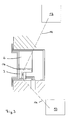
- FIG. 3 an advantageous front-side arrangement of the device 3 is shown in a receiving space 17 of the device base 6.
- a removable cover (not shown) closes this receiving space 17, in which the device 3 can be positively inserted and latched in a form-locking manner.
- the connection contacts 16 are guided protected against contact from the device 3, which are electrically contacted with the terminals 9 in the device base 6.
- the front element 8 and then the cover of the receiving space 17 is removed. Due to the positive connection and a cylindrical spatial extension, the device 3 can be pushed linearly without tilting up to the stop in the circular segment-shaped receiving space 17. It is automatically mechanically locked as well as electrically connected to the mains voltage. On the upper side of the device 3 are lighting elements to light signals targeted To be able to direct display elements in the front element 8. Finally, the front element 8 is mounted again. In this embodiment, neither an expansion of the installation device 2 nor additional connection work is necessary.
Landscapes
- Engineering & Computer Science (AREA)
- Microelectronics & Electronic Packaging (AREA)
- Details Of Indoor Wiring (AREA)
- Casings For Electric Apparatus (AREA)
Abstract
Description
- Die Erfindung betrifft eine Installationsanordnung für die Gebäudesystemtechnik nach dem Oberbegriff des Patentanspruches 1.
- Elektrische Installationsgeräte werden im Rahmen der Gebäudesystemtechnik sowohl bei der Erstausstattung als auch im Nachrüstbereich eingesetzt. Häufig ist es wichtig, das jeweilige elektrische Installationsgerät funktional aufrüsten zu können. Aus diesem Grund hat es sich als vorteilhaft erwiesen, modulare Baugruppen zu schaffen, mit denen bei Bedarf das vorhandene Gerät ergänzt werden kann. Aus dem Stand der Technik, beispielsweise aus der
EP 0 281 969 B1 , ist eine netzversorgte Steckdose bekannt, bei der eine Baugruppe rückseitig befestigt werden kann, die in Form eines Überspannungsschutzes funktional auf die Steckdose einwirkt. - Neben herkömmlichen leitungsgebundenen Installationssystemen existieren Systeme bei denen Datentelegramme drahtlos mittels Funksignalen von Bedienelementen und Sensoren zur lastschaltenden Aktorik übertragen werden, die dann leitungsgebunden die jeweiligen Verbraucher mit Netzspannung versorgt. Aufgrund eingeschränkter Sendeleistung und räumlich bedingter Störungen des Funkverkehrs werden oftmals Signal verstärkende bzw. wiederholende Bauelemente sogenannte Repeater bzw. Router verwendet, um eine einwandfreie Datenübermittlung zu gewährleisten. Diese Geräte werden an exponierten Stellen positioniert und müssen aufgrund permanenter Sendebelastung mit einer zuverlässigen Spannungsversorgung ausgestattet sein. Da temporäre Energiespeicher einem hohen Wechselzyklus unterliegen, wird die Versorgung mit Netzspannung bevorzugt. Abhängig vom Montageort ist folglich eine entsprechende Erweiterung der Leitungsinstallation erforderlich.
- Die Aufgabe der vorliegenden Erfindung besteht deshalb darin, die vorstehend genannten Nachteile zu beseitigen und eine Installationsanordnung zu schaffen, die den Installationsaufwand verringert und eine permanente Spannungsversorgung gewährleistet.
- Gelöst wird diese Aufgabe durch die im Patentanspruch 1 angegebenen Merkmale. Vorteilhafte Ausgestaltungen ergeben sich aus den Unteransprüchen.
- Die Erfindung gemäß dem Patentanspruch 1 weist den Vorteil auf, dass Installationsplätze und Versorgungsleitungen von elektrischen Geräten zusätzlich genutzt werden, um auch funktionsfremde Geräte mit Spannung zu versorgen. Bisher wurden diese Geräte an separaten Montageplätzen installiert, so dass eine zusätzliche Verlegung der Versorgungsleitungen einschließlich optisch nachteiliger Aufputzinstallationen oder aufwendiger Unterputzinstallationen erforderlich war. Durch die erfindungsgemäße Anordnung wird außerdem mit geringem Installationsaufwand eine verdeckte Installation dieser Geräte möglich. Interferenzen zwischen den Geräten entstehen nicht. Darüber hinaus wird eine permanente Spannungsversorgung ermöglicht, so dass auf temporäre Energiespeicher für die Geräte verzichtet werden kann.
- Eine bevorzugte Anwendung der Erfindung ergibt sich bei der Kombination von herkömmlichen leitungsgebundenen Geräten mit drahtlos kommunizierenden, vorzugsweise auf Funk basierenden, Geräten. Derartige Geräte können, sofern sie keinen funktionsspezifischen Montageort haben, weitgehend ortsunabhängig platziert werden, wie z. B. sogenannte Repeater oder Router, die Funksignale empfangen, selektieren, verstärken und/oder weiterleiten. Ein nutzbarer Installationsplatz eines drahtgebundenen Installationsgerätes, vorzugsweise eine Steckdose, ist in der Regel in dem Aktionsradius jedes entsprechenden Funkgerätes vorhanden.
- Da die zu adaptierenden Geräte funktional in sich geschlossene Baugruppen bilden, sind am Installationsgerät keine Veränderungen notwendig. In Funk basierenden Geräten wird eine eingehende Netzspannung in eine geeignete kleinere Spannung und/oder andere Energieart für die Funkbauelemente umgewandelt. Optional sind visuell oder akustisch wirkende Bauelemente beispielsweise für Zustandsmeldungen angeordnet.
- Die erfindungsgemäße Anordnung kann sowohl in Aufputz- als auch in Unterputzinstallationen realisiert werden. Eine Adaption an vorhandene Installationsgeräte ist unproblematisch, da an den Anschlussklemmen ein zusätzlicher Abgriff jederzeit möglich ist.
- Die Anordnung des Gerätes erfolgt in einer Ausführung rückseitig des drahtgebundenen Installationsgerätes, da hier ausreichend Montageplatz vorhanden ist. Installationstechnisch ist dabei die Verwendung einer tiefen Installationsdose vorteilhaft, da dann eine leichte Montage möglich ist.
- In bevorzugt ausgebildeten Installationsgeräten ist eine platzsparende Anordnung des drahtlos arbeitenden Gerätes möglich. Dabei wird durch eine vorteilhafte Bauteilanordnung innerhalb der vorhandenen Struktur des Gerätesockels ein Aufnahmeraum geschaffen, so dass das Gerät vorzugsweise formschlüssig und flächenbündig in den Gerätesockel integriert werden kann. Es wird kein zusätzlicher Platz vor oder hinter dem Gerätesockel benötigt, um das Gerät anzuordnen. Somit wird ein universell verwendbares Installationsgerät geschaffen, das im Bedarfsfall mit einem geeigneten Gerät kombiniert werden kann. Die allgemein vorhandene Struktur von Gerätesockeln, insbesondere deren Abmessungen und deren Befestigungs- und Kontaktpunkte, bleibt unverändert erhalten.
- Besonders vorteilhaft ist dabei die Ausbildung eines frontseitig zugänglichen Aufnahmeraumes innerhalb des Gerätesockels, da der Gerätesockel für die Montage dann nicht aus dem Installationsgehäuse gelöst werden muss. Lediglich das entsprechende Frontelement muss entfernt werden, um das Gerät einsetzen zu können. Es entsteht ein erheblicher Installationsvorteil. Darüber hinaus können funktionsspezifischen Frontelemente innerhalb einer Produktserie beim Austausch eines bestehenden Installationsgerätes weiter verwendet werden.
- Der elektrische Anschluss des Gerätes erfolgt indirekt an der Versorgungsspannung des Installationsgerätes, vorteilhafterweise mit einer lösbaren Technik, insbesondere mittels Steckung, an die Anschlussklemmen oder Kontaktelemente des Installationsgerätes. Die Kontaktierung des Gerätes erfolgt vorteilhafterweise während der Gerätemontage selbsttätig. Die entsprechenden Kontaktelemente des Installationsgerätes und des zu adaptierenden Gerätes sind berührungsgeschützt angeordnet. Denkbar ist jedoch auch eine unlösbare Verbindung.
- Eine mögliche Ausführungsform der Erfindung ergibt sich durch eine elektrische Steckdose mit einem rückseitig des Gerätesockels angeordneten und über Anschlussklemmen des Gerätesockels mit der Netzspannung versorgten Funk-Repeater.
- Weitere Einzelheiten, Merkmale und Vorteile der Erfindung ergeben sich aus nachfolgender Beschreibung bevorzugter Ausführungsbeispiele anhand der Zeichnungen.
- Es zeigen:
- Figur 1
- schematisch eine erfindungsgemäße Installationsanordnung mit rückseitiger Geräteanordnung.
- Figur 2
- ein weiteres Ausführungsbeispiel mit rückseitiger Geräteanordnung.
- Figur 3
- ein weiteres Ausführungsbeispiel mit frontseitiger Geräteanordnung.
- Gleiche oder gleichwirkende Bauteile sind in der nachfolgenden Beschreibung mit gleichen Bezugszeichen versehen.
- Nachfolgend wird der Aufbau und die Funktionsweise der erfindungsgemäßen Installationsanordnung 1 schematisch anhand von drei Alternativen näher beschrieben. Beispielhaft ist dabei ein erstes elektrisches Gerät 2 in Form einer Steckdose dargestellt, die mit einem zweiten elektrischen Gerät 3 in Form eines Funk basierenden Repeaters bestückt ist.
- Die Installationsanordnung 1 weist ein erstes elektrisches Gerät 2 auf, das in einem Installationsgehäuse 4 befestigt ist, welches ortsfest in einer Gebäudewand 5 fixiert ist. Das Gerät 2 weist einen Gerätesockel 6 auf, den außenseitig ein Tragrahmen 7 umgibt, der die Befestigung des Gerätes 2 in dem Installationsgehäuse 4 ermöglicht. Frontseitig ist ein funktionsspezifisches Frontelement 8 befestigt, das je nach Anwendung ein- oder mehrteilig sein kann. In dem Gerätesockel 6 sind Anschlussklemmen 9 und damit verbundene metallische Kontaktelemente angeordnet, in die frontseitig Steckerstifte eines nicht dargestellten Gerätesteckers gesteckt werden. Des weiteren ist in dem Gerätesockel 6 ein Erdungsbügel angeordnet, der zur frontseitigen Kontaktierung eines Erdungskontaktes des Gerätesteckers dient. Eine wandseitig verlegte Versorgungsleitung 10 versorgt das Gerät 2 mit einer Netzspannung, wobei die einzelnen Leitungen 11 lösbar in den Anschlussklemmen 9 fixiert sind.
- Darüber hinaus ist ein funkbasierendes Teilsystem angeordnet, das aus verschiedenen Geräten 3, 12, 13 besteht, die mittels Funksignalen 14 Datentelegramme austauschen, wobei das Gerät 3 beispielsweise von einem Gerät 12 eingehende Datentelegramme empfängt, gegebenenfalls selektiert, verstärkt und an ein weiteres Gerät 13 sendet.
- Das Gerät 3 ist in einem Freiraum 15 in dem Installationsgehäuse 4 hinter dem Gerät 2 angeordnet. Das Gerät 3 ist über Anschlusskontakte 16 lösbar mit den Anschlussklemmen 9 des Installationsgerätes 2 verbunden und somit ebenfalls an das Versorgungsnetz angeschlossen. In dem Gerät 3 sind diverse elektronische Bauteile angeordnet, mit denen eine Transformation der eingehenden Netzspannung in eine geeignete Versorgungsspannung für die Funkbauelemente realisiert wird. Das Gerät 3 fungiert als Repeater und kann innerhalb systemtechnisch bedingter Grenzen an beliebiger Stelle platziert sein. Durch die Anordnung an dem Installationsgerät 2 kann die entsprechende Leitungsinstallation und die Netzspannung mitgenutzt werden und separate Installationsarbeiten entfallen.
- Gemäß
Figur 2 ist eine vorteilhafte rückseitige Anordnung des Gerätes 3 innerhalb eines Aufnahmeraumes 17 in dem Gerätesockel 6 dargestellt. - Im unbestückten Zustand verschließt eine entfernbare Abdeckung (nicht dargestellt) diesen Aufnahmeraum 17, in den das Gerät 3 formschlüssig einsetzbar und rastend fixierbar ist. Bodenseitig sind die Anschlusskontakte 16 berührungsgeschützt aus dem Gerät 3 geführt, die mit den Anschlussklemmen 9 in dem Gerätesockel 6 elektrisch kontaktierbar sind. Für die Montage des Gerätes 3 wird das Frontelement 8 entfernt, der Gerätesockel 6 aus dem Installationsgehäuse 4 gelöst und anschließend die Abdeckung des Aufnahmeraumes 17 entfernt. Das Gerät 3 wird in den Aufnahmeraum 17 geschoben. Automatisch wird es dabei sowohl mechanisch verrastet als auch elektrisch an die Netzspannung angeschlossen. Abschließend wird der so bestückte Gerätesockel 6 wieder in dem Installationsgehäuse 4 befestigt und das Frontelement 8 montiert.
- Gemäß
Figur 3 ist eine vorteilhafte frontseitige Anordnung des Gerätes 3 in einem Aufnahmeraum 17 des Gerätesockels 6 dargestellt. Im unbestückten Zustand verschließt eine entfernbare Abdeckung (nicht dargestellt) diesen Aufnahmeraum 17, in den das Gerät 3 formschlüssig einsetzbar und rastend fixierbar ist. Bodenseitig sind die Anschlusskontakte 16 berührungsgeschützt aus dem Gerät 3 geführt, die mit den Anschlussklemmen 9 in dem Gerätesockel 6 elektrisch kontaktierbar sind. - Für die Montage des Gerätes 3 wird das Frontelement 8 und anschließend die Abdeckung des Aufnahmeraumes 17 entfernt. Aufgrund des Formschlusses und einer zylindrischen Raumerstreckung kann das Gerät 3 ohne Verkantungen linear bis zum Anschlag in den kreissegmentförmigen Aufnahmeraum 17 geschoben werden. Automatisch wird es dabei sowohl mechanisch verrastet als auch elektrisch an die Netzspannung angeschlossen. Oberseitig des Gerätes 3 befinden sich Leuchtelemente, um Lichtsignale gezielt an Anzeigeelemente in dem Frontelement 8 leiten zu können. Abschließend wird das Frontelement 8 wieder montiert. In diesem Ausführungsbeispiel ist weder ein Ausbau des Installationsgerätes 2 noch sind zusätzliche Anschlussarbeiten notwendig.
- Die vorstehende Beschreibung des Ausführungsbeispieles dient nur zu illustrativen Zwecken und nicht zum Zwecke der Beschränkung der Erfindung. Im Rahmen der Erfindung sind verschiedene Änderungen und Modifikationen möglich, ohne den Umfang der Erfindung sowie ihrer Äquivalente zu verlassen.
-
- 1
- Installationsanordnung
- 2
- Erstes Gerät
- 3
- Zweites Gerät
- 4
- Installationsgehäuse
- 5
- Gebäudewand
- 6
- Gerätesockel
- 7
- Tragrahmen
- 8
- Frontelement
- 9
- Anschlussklemmen
- 10
- Versorgungsleitung
- 11
- Leitungen
- 12
- Gerät
- 13
- Gerät
- 14
- Funksignal
- 15
- Freiraum
- 16
- Anschlusskontakte
- 17
- Aufnahmeraum
Claims (13)
- Installationsanordnung für die Gebäudesystemtechnik, bestehend aus mehreren elektrischen Geräten (2, 3, 12, 13), wobei ein erstes Gerät (2) einen Gerätesockel (6) aufweist, der ortsfest in einem Installationsgehäuse (4) befestigt ist, der an eine Netzspannung angeschlossen ist, und an dem frontseitig ein Frontelement (8) befestigt ist, und wobei ein zweites Gerät (3) an dem Gerätesockel (6) des ersten Gerätes (2) angeordnet ist und an die Versorgungsspannung des ersten Gerätes (2) angeschlossen ist und wobei das zweite Gerät (3) funktional unabhängig von dem ersten Gerät (2) ist.
- Installationsanordnung nach Patentanspruch 1, dadurch gekennzeichnet, dass das zweite Gerät (3) mit weiteren Geräten (12, 13) drahtlos kommuniziert.
- Installationsanordnung nach einem der vorhergehenden Patentansprüche, dadurch gekennzeichnet, dass drahtlose Signale in dem zweiten Gerät (3) empfangbar, verstärkbar und/oder weiterleitbar sind.
- Installationsanordnung nach einem der vorhergehenden Patentansprüche, dadurch gekennzeichnet, dass die Übertragung der Signale (14) mittels Funkwellen erfolgt.
- Installationsanordnung nach einem der vorhergehenden Patentansprüche, dadurch gekennzeichnet, dass die in dem zweiten Gerät (3) eingehende Netzspannung transformiert wird.
- Installationsanordnung nach einem der vorhergehenden Patentansprüche, dadurch gekennzeichnet, dass das zweite Gerät (3) in dem Installationsgehäuse (4) angeordnet ist.
- Installationsanordnung nach einem der vorhergehenden Patentansprüche, dadurch gekennzeichnet, dass das zweite Gerät (3) lösbar an dem Gerätesockel (6) des ersten Gerätes (2) angeordnet ist.
- Installationsanordnung nach einem der vorhergehenden Patentansprüche, dadurch gekennzeichnet, dass das zweite Gerät (3) frontseitig oder rückseitig des Gerätesockels (6) angeordnet ist.
- Installationsanordnung nach einem der vorhergehenden Patentansprüche, dadurch gekennzeichnet, dass der Gerätesockel (6) einen Aufnahmeraum (17) für ein formschlüssig einsteckbares zweites Gerät (3) aufweist.
- Installationsanordnung nach einem der vorhergehenden Patentansprüche, dadurch gekennzeichnet, dass das zweite Gerät (3) frontseitig und flächenbündig in dem Aufnahmeraum (17) des Gerätesockels (6) angeordnet ist.
- Installationsanordnung nach einem der vorhergehenden Patentansprüche, dadurch gekennzeichnet, dass bei der mechanischen Positionierung des zweiten Gerätes (3) an dem Gerätesockel (6) eine selbsttätige elektrische Kontaktierung erfolgt.
- Installationsanordnung nach einem der vorhergehenden Patentansprüche, dadurch gekennzeichnet, dass das erste Gerät (2) als elektrische Steckdose ausgeführt ist.
- Installationsanordnung nach einem der vorhergehenden Patentansprüche, dadurch gekennzeichnet, dass das zweite Gerät (3) als drahtlos kommunizierender Router oder Repeater ausgeführt ist.
Applications Claiming Priority (1)
| Application Number | Priority Date | Filing Date | Title |
|---|---|---|---|
| DE102007063586A DE102007063586A1 (de) | 2007-12-21 | 2007-12-21 | Installationsanordnung |
Publications (2)
| Publication Number | Publication Date |
|---|---|
| EP2073322A2 true EP2073322A2 (de) | 2009-06-24 |
| EP2073322A3 EP2073322A3 (de) | 2011-03-30 |
Family
ID=40474199
Family Applications (1)
| Application Number | Title | Priority Date | Filing Date |
|---|---|---|---|
| EP08021989A Ceased EP2073322A3 (de) | 2007-12-21 | 2008-12-18 | Installationsanordnung |
Country Status (2)
| Country | Link |
|---|---|
| EP (1) | EP2073322A3 (de) |
| DE (1) | DE102007063586A1 (de) |
Families Citing this family (1)
| Publication number | Priority date | Publication date | Assignee | Title |
|---|---|---|---|---|
| DE102010022725A1 (de) * | 2010-06-04 | 2011-12-08 | Hans-Dieter Leibold | Analysevorrichtung für Stromverbraucher |
Citations (1)
| Publication number | Priority date | Publication date | Assignee | Title |
|---|---|---|---|---|
| EP0281969B1 (de) | 1987-03-10 | 1994-02-09 | Asea Brown Boveri Aktiengesellschaft | Steckdose mit Zusatzmodul |
Family Cites Families (8)
| Publication number | Priority date | Publication date | Assignee | Title |
|---|---|---|---|---|
| US6160728A (en) * | 1999-05-26 | 2000-12-12 | Advanced Micro Devices, Inc. | Dual-mode AC/DC electrical receptacle |
| US6993289B2 (en) * | 2000-08-02 | 2006-01-31 | Simple Devices | System including a wall switch device and a system including a power outlet device and methods for using the same |
| US6993417B2 (en) * | 2001-09-10 | 2006-01-31 | Osann Jr Robert | System for energy sensing analysis and feedback |
| DE602004026108D1 (de) * | 2003-11-07 | 2010-04-29 | Mpathx Llc | Automatische mess-leistungssysteme und verfahren |
| ATE350785T1 (de) * | 2004-02-02 | 2007-01-15 | Alombard Sas | Elektrische anschlussklemme und anwendung in einer steckdose |
| DE102005010949A1 (de) * | 2005-03-10 | 2006-09-14 | Abb Patent Gmbh | System zur Freigabe eines elektrischen Installationsgerätes |
| EP1929591A4 (de) * | 2005-09-02 | 2013-04-03 | Kim Sun Young | Steckerbuchse mit automatischem standby-stromausschalten |
| DE202005015140U1 (de) * | 2005-09-24 | 2005-12-08 | Kleinknecht Systemtechnik Gmbh | Elektrische Steckdose oder elektrischer Schalter |
-
2007
- 2007-12-21 DE DE102007063586A patent/DE102007063586A1/de not_active Ceased
-
2008
- 2008-12-18 EP EP08021989A patent/EP2073322A3/de not_active Ceased
Patent Citations (1)
| Publication number | Priority date | Publication date | Assignee | Title |
|---|---|---|---|---|
| EP0281969B1 (de) | 1987-03-10 | 1994-02-09 | Asea Brown Boveri Aktiengesellschaft | Steckdose mit Zusatzmodul |
Also Published As
| Publication number | Publication date |
|---|---|
| EP2073322A3 (de) | 2011-03-30 |
| DE102007063586A1 (de) | 2009-07-02 |
Similar Documents
| Publication | Publication Date | Title |
|---|---|---|
| EP2057718B1 (de) | Energieschienensystem | |
| DE29912331U1 (de) | Elektrischer Vielzweck-Verbinder | |
| DE102010007502A1 (de) | Elektrisches Unterputz-Installationsgerät zur Aufnahme eines mobilen Audio- und Kommunikationsgerätes | |
| EP3744159B1 (de) | Steckverbinder und elektronisches gerät | |
| EP3176878B1 (de) | Kabelanschlusskasten und überspannungsschutzmodul für einen kabelanschlusskasten | |
| EP2073322A2 (de) | Installationsanordnung | |
| EP3671976A1 (de) | Elektrische steckverbindungseinrichtung und elektrisches gerät hiermit | |
| EP2253047B1 (de) | Funktionserweiterbarer anschlussblock und modul | |
| EP2073321B1 (de) | Installationsgerät | |
| DE202014100207U1 (de) | Koppler für Mittelspannungs-Powerline-Communication | |
| DE102007063584B4 (de) | Elektrisches Installationsgerät | |
| DE102010040595A1 (de) | Verbindungssystem sowie Aufnahmeeinheit für ein Steuergerät | |
| DE2616392C2 (de) | Geräteeinsatz der elektrischen Nachrichtenübertragungstechnik | |
| EP2351176B1 (de) | Elektrisches installationsgerät | |
| EP4070985A1 (de) | Elektrische leistungssteuereinheit und ladestation | |
| DE202011000284U1 (de) | Funktionsüberprüfungseinrichtung für Photovoltaikanlagen | |
| EP2315319A1 (de) | Elektrische Schutzkontaktsteckdose | |
| DE202014000549U1 (de) | Netzwerkzugangsvorrichtung | |
| DE102009008905A1 (de) | Anschlußdose, Endgerät und Signalübertragungsvorrichtung | |
| DE202013008312U1 (de) | Gefahrenmelderzentrale mit integrierter KNX-Busschnittstelle | |
| EP2214416B1 (de) | Patch-Panel sowie Verfahren zu seiner Installation | |
| DE20311394U1 (de) | Schutzvorrichtung | |
| DE2635336C2 (de) | Verdrahtung von tragbaren Geräten der Funkortungstechnik | |
| DE102022120668A1 (de) | Auslesevorrichtung zum Auslesen von Daten eines Verbrauchszählers | |
| DE102018106003A1 (de) | Anschlussklemme |
Legal Events
| Date | Code | Title | Description |
|---|---|---|---|
| PUAI | Public reference made under article 153(3) epc to a published international application that has entered the european phase |
Free format text: ORIGINAL CODE: 0009012 |
|
| AK | Designated contracting states |
Kind code of ref document: A2 Designated state(s): AT BE BG CH CY CZ DE DK EE ES FI FR GB GR HR HU IE IS IT LI LT LU LV MC MT NL NO PL PT RO SE SI SK TR |
|
| AX | Request for extension of the european patent |
Extension state: AL BA MK RS |
|
| PUAL | Search report despatched |
Free format text: ORIGINAL CODE: 0009013 |
|
| AK | Designated contracting states |
Kind code of ref document: A3 Designated state(s): AT BE BG CH CY CZ DE DK EE ES FI FR GB GR HR HU IE IS IT LI LT LU LV MC MT NL NO PL PT RO SE SI SK TR |
|
| AX | Request for extension of the european patent |
Extension state: AL BA MK RS |
|
| 17P | Request for examination filed |
Effective date: 20110914 |
|
| AKX | Designation fees paid |
Designated state(s): AT BE BG CH CY CZ DE DK EE ES FI FR GB GR HR HU IE IS IT LI LT LU LV MC MT NL NO PL PT RO SE SI SK TR |
|
| 17Q | First examination report despatched |
Effective date: 20120302 |
|
| APBK | Appeal reference recorded |
Free format text: ORIGINAL CODE: EPIDOSNREFNE |
|
| APBN | Date of receipt of notice of appeal recorded |
Free format text: ORIGINAL CODE: EPIDOSNNOA2E |
|
| APBR | Date of receipt of statement of grounds of appeal recorded |
Free format text: ORIGINAL CODE: EPIDOSNNOA3E |
|
| APAF | Appeal reference modified |
Free format text: ORIGINAL CODE: EPIDOSCREFNE |
|
| PUAJ | Public notification under rule 129 epc |
Free format text: ORIGINAL CODE: 0009425 |
|
| 32PN | Public notification |
Free format text: LADUNG ZUR MUENDLICHEN VERHANDLUNG |
|
| APBT | Appeal procedure closed |
Free format text: ORIGINAL CODE: EPIDOSNNOA9E |
|
| STAA | Information on the status of an ep patent application or granted ep patent |
Free format text: STATUS: THE APPLICATION HAS BEEN REFUSED |
|
| 18R | Application refused |
Effective date: 20201008 |