EP2073322A2 - Agencement d'installation - Google Patents
Agencement d'installation Download PDFInfo
- Publication number
- EP2073322A2 EP2073322A2 EP08021989A EP08021989A EP2073322A2 EP 2073322 A2 EP2073322 A2 EP 2073322A2 EP 08021989 A EP08021989 A EP 08021989A EP 08021989 A EP08021989 A EP 08021989A EP 2073322 A2 EP2073322 A2 EP 2073322A2
- Authority
- EP
- European Patent Office
- Prior art keywords
- installation
- arrangement according
- installation arrangement
- base
- devices
- Prior art date
- Legal status (The legal status is an assumption and is not a legal conclusion. Google has not performed a legal analysis and makes no representation as to the accuracy of the status listed.)
- Ceased
Links
Images


Classifications
-
- H—ELECTRICITY
- H01—ELECTRIC ELEMENTS
- H01R—ELECTRICALLY-CONDUCTIVE CONNECTIONS; STRUCTURAL ASSOCIATIONS OF A PLURALITY OF MUTUALLY-INSULATED ELECTRICAL CONNECTING ELEMENTS; COUPLING DEVICES; CURRENT COLLECTORS
- H01R24/00—Two-part coupling devices, or either of their cooperating parts, characterised by their overall structure
- H01R24/76—Two-part coupling devices, or either of their cooperating parts, characterised by their overall structure with sockets, clips or analogous contacts and secured to apparatus or structure, e.g. to a wall
- H01R24/78—Two-part coupling devices, or either of their cooperating parts, characterised by their overall structure with sockets, clips or analogous contacts and secured to apparatus or structure, e.g. to a wall with additional earth or shield contacts
-
- H—ELECTRICITY
- H01—ELECTRIC ELEMENTS
- H01R—ELECTRICALLY-CONDUCTIVE CONNECTIONS; STRUCTURAL ASSOCIATIONS OF A PLURALITY OF MUTUALLY-INSULATED ELECTRICAL CONNECTING ELEMENTS; COUPLING DEVICES; CURRENT COLLECTORS
- H01R13/00—Details of coupling devices of the kinds covered by groups H01R12/70 or H01R24/00 - H01R33/00
- H01R13/648—Protective earth or shield arrangements on coupling devices, e.g. anti-static shielding
- H01R13/655—Protective earth or shield arrangements on coupling devices, e.g. anti-static shielding with earth brace
-
- H—ELECTRICITY
- H01—ELECTRIC ELEMENTS
- H01R—ELECTRICALLY-CONDUCTIVE CONNECTIONS; STRUCTURAL ASSOCIATIONS OF A PLURALITY OF MUTUALLY-INSULATED ELECTRICAL CONNECTING ELEMENTS; COUPLING DEVICES; CURRENT COLLECTORS
- H01R13/00—Details of coupling devices of the kinds covered by groups H01R12/70 or H01R24/00 - H01R33/00
- H01R13/66—Structural association with built-in electrical component
- H01R13/665—Structural association with built-in electrical component with built-in electronic circuit
- H01R13/6683—Structural association with built-in electrical component with built-in electronic circuit with built-in sensor
-
- H—ELECTRICITY
- H01—ELECTRIC ELEMENTS
- H01R—ELECTRICALLY-CONDUCTIVE CONNECTIONS; STRUCTURAL ASSOCIATIONS OF A PLURALITY OF MUTUALLY-INSULATED ELECTRICAL CONNECTING ELEMENTS; COUPLING DEVICES; CURRENT COLLECTORS
- H01R2103/00—Two poles
-
- H—ELECTRICITY
- H02—GENERATION; CONVERSION OR DISTRIBUTION OF ELECTRIC POWER
- H02J—ELECTRIC POWER NETWORKS; CIRCUIT ARRANGEMENTS OR SYSTEMS FOR SUPPLYING OR DISTRIBUTING ELECTRIC POWER; SYSTEMS FOR STORING ELECTRIC ENERGY
- H02J13/00—Circuit arrangements for providing remote monitoring or remote control of equipment in a power distribution network
- H02J13/13—Circuit arrangements for providing remote monitoring or remote control of equipment in a power distribution network characterised by the transmission of data to equipment in the power network
- H02J13/1331—Circuit arrangements for providing remote monitoring or remote control of equipment in a power distribution network characterised by the transmission of data to equipment in the power network using wireless data transmission
-
- H—ELECTRICITY
- H02—GENERATION; CONVERSION OR DISTRIBUTION OF ELECTRIC POWER
- H02J—ELECTRIC POWER NETWORKS; CIRCUIT ARRANGEMENTS OR SYSTEMS FOR SUPPLYING OR DISTRIBUTING ELECTRIC POWER; SYSTEMS FOR STORING ELECTRIC ENERGY
- H02J13/00—Circuit arrangements for providing remote monitoring or remote control of equipment in a power distribution network
- H02J13/18—Circuit arrangements for providing remote monitoring or remote control of equipment in a power distribution network characterised by the remotely-controlled equipment, e.g. converters or transformers
- H02J13/38—Circuit arrangements for providing remote monitoring or remote control of equipment in a power distribution network characterised by the remotely-controlled equipment, e.g. converters or transformers the equipment being power outlets
-
- Y—GENERAL TAGGING OF NEW TECHNOLOGICAL DEVELOPMENTS; GENERAL TAGGING OF CROSS-SECTIONAL TECHNOLOGIES SPANNING OVER SEVERAL SECTIONS OF THE IPC; TECHNICAL SUBJECTS COVERED BY FORMER USPC CROSS-REFERENCE ART COLLECTIONS [XRACs] AND DIGESTS
- Y02—TECHNOLOGIES OR APPLICATIONS FOR MITIGATION OR ADAPTATION AGAINST CLIMATE CHANGE
- Y02B—CLIMATE CHANGE MITIGATION TECHNOLOGIES RELATED TO BUILDINGS, e.g. HOUSING, HOUSE APPLIANCES OR RELATED END-USER APPLICATIONS
- Y02B90/00—Enabling technologies or technologies with a potential or indirect contribution to GHG emissions mitigation
- Y02B90/20—Smart grids as enabling technology in buildings sector
-
- Y—GENERAL TAGGING OF NEW TECHNOLOGICAL DEVELOPMENTS; GENERAL TAGGING OF CROSS-SECTIONAL TECHNOLOGIES SPANNING OVER SEVERAL SECTIONS OF THE IPC; TECHNICAL SUBJECTS COVERED BY FORMER USPC CROSS-REFERENCE ART COLLECTIONS [XRACs] AND DIGESTS
- Y04—INFORMATION OR COMMUNICATION TECHNOLOGIES HAVING AN IMPACT ON OTHER TECHNOLOGY AREAS
- Y04S—SYSTEMS INTEGRATING TECHNOLOGIES RELATED TO POWER NETWORK OPERATION, COMMUNICATION OR INFORMATION TECHNOLOGIES FOR IMPROVING THE ELECTRICAL POWER GENERATION, TRANSMISSION, DISTRIBUTION, MANAGEMENT OR USAGE, i.e. SMART GRIDS
- Y04S20/00—Management or operation of end-user stationary applications or the last stages of power distribution; Controlling, monitoring or operating thereof
-
- Y—GENERAL TAGGING OF NEW TECHNOLOGICAL DEVELOPMENTS; GENERAL TAGGING OF CROSS-SECTIONAL TECHNOLOGIES SPANNING OVER SEVERAL SECTIONS OF THE IPC; TECHNICAL SUBJECTS COVERED BY FORMER USPC CROSS-REFERENCE ART COLLECTIONS [XRACs] AND DIGESTS
- Y04—INFORMATION OR COMMUNICATION TECHNOLOGIES HAVING AN IMPACT ON OTHER TECHNOLOGY AREAS
- Y04S—SYSTEMS INTEGRATING TECHNOLOGIES RELATED TO POWER NETWORK OPERATION, COMMUNICATION OR INFORMATION TECHNOLOGIES FOR IMPROVING THE ELECTRICAL POWER GENERATION, TRANSMISSION, DISTRIBUTION, MANAGEMENT OR USAGE, i.e. SMART GRIDS
- Y04S40/00—Systems for electrical power generation, transmission, distribution or end-user application management characterised by the use of communication or information technologies, or communication or information technology specific aspects supporting them
- Y04S40/12—Systems for electrical power generation, transmission, distribution or end-user application management characterised by the use of communication or information technologies, or communication or information technology specific aspects supporting them characterised by data transport means between the monitoring, controlling or managing units and monitored, controlled or operated electrical equipment
- Y04S40/126—Systems for electrical power generation, transmission, distribution or end-user application management characterised by the use of communication or information technologies, or communication or information technology specific aspects supporting them characterised by data transport means between the monitoring, controlling or managing units and monitored, controlled or operated electrical equipment using wireless data transmission
Definitions
- the invention relates to an installation arrangement for the building system technology according to the preamble of claim 1.
- the object of the present invention is therefore to eliminate the above-mentioned disadvantages and to provide an installation arrangement which reduces the installation effort and ensures a permanent power supply.
- the invention according to claim 1 has the advantage that installation sites and supply lines of electrical devices are also used to supply even non-functional devices with voltage. So far, these devices have been installed on separate assembly sites, so that an additional installation of the supply lines including visually disadvantageous surface-mounted installations or complex flush-mounted installations was required.
- the inventive arrangement also a covert installation of these devices is possible with little installation effort. Interference between the devices does not arise. In addition, a permanent power supply is possible, so that can be dispensed with temporary energy storage for the devices.
- a preferred application of the invention results from the combination of conventional wireline devices with wireless communicating, preferably radio based, devices. Such devices can, if they have no function-specific installation location, are largely placed regardless of location, such. B. so-called repeaters or routers that receive radio signals, select, amplify and / or forward.
- a usable installation space of a wired installation device, preferably a socket, is usually present in the operating radius of each corresponding radio.
- an incoming line voltage is converted to a suitable lower voltage and / or different type of energy for the radio components.
- visually or acoustically acting components are arranged, for example, for status messages.
- the arrangement according to the invention can be realized both in surface-mounted and in-wall installations.
- An adaptation to existing installation devices is not a problem, as at the terminals an additional tap is possible at any time.
- the arrangement of the device is done in a version on the back of the wired installation device, since there is sufficient mounting space available. Installation technology, the use of a deep installation box is advantageous because then easy mounting is possible.
- a space-saving arrangement of the wireless device is possible.
- a receiving space is created by an advantageous component arrangement within the existing structure of the device base, so that the device can be preferably integrated in a form-fitting and flush-mounted in the device base.
- the unit base There is no need for extra space in front of or behind the unit base to place the unit.
- a universally usable installation device is created, if necessary can be combined with a suitable device.
- the generally existing structure of device bases, in particular their dimensions and their attachment and contact points remains unchanged.
- the electrical connection of the device is made indirectly to the supply voltage of the installation device, advantageously with a detachable technology, in particular by means of mating, to the terminals or contact elements of the installation device.
- the contacting of the device is advantageously carried out automatically during the device assembly.
- the corresponding contact elements of the installation device and the device to be adapted are arranged protected against contact. It is also conceivable, however, an inseparable connection.
- a possible embodiment of the invention results from an electrical socket with a back of the device base arranged and supplied via terminals of the device base with the mains voltage radio repeater.
- a first electrical device 2 in the form of a socket is shown, which is equipped with a second electrical device 3 in the form of a radio-based repeater.
- the installation arrangement 1 has a first electrical device 2, which is fastened in an installation housing 4, which is fixedly fixed in a building wall 5.
- the device 2 has a device base 6, the outside of a support frame 7 surrounds, which allows the attachment of the device 2 in the installation housing 4.
- Front side, a function-specific front element 8 is attached, depending on the application can be one or more parts.
- terminals 9 and associated metallic contact elements are arranged in the front plug pins of a device plug, not shown, are inserted.
- a grounding strap is arranged in the device base 6, which serves for the front-side contacting of a grounding contact of the device plug.
- a wall-mounted supply line 10 supplies the device 2 with a mains voltage, wherein the individual lines 11 are releasably fixed in the terminals 9.
- a radio-based subsystem which consists of various devices 3, 12, 13, which exchange data signals by means of radio signals 14, wherein the device 3 receives, for example from a device 12 incoming data telegrams, optionally selected, amplified and sends to another device 13 ,
- the device 3 is arranged in a free space 15 in the installation housing 4 behind the device 2.
- the device 3 is connected via terminal contacts 16 releasably connected to the terminals 9 of the installation device 2 and thus also connected to the supply network.
- various electronic components are arranged, with which a transformation of the incoming mains voltage is realized in a suitable supply voltage for the radio components.
- the device 3 acts as a repeater and can be placed within system-related limits at any point.
- the arrangement on the installation device 2, the corresponding line installation and the mains voltage can be shared and separate installation work accounts.
- FIG. 2 an advantageous rear arrangement of the device 3 is shown within a receiving space 17 in the device base 6.
- a removable cover closes this receiving space 17, in which the device 3 can be positively inserted and latched in a form-locking manner.
- the connection contacts 16 are guided protected against contact from the device 3, which are electrically contacted with the terminals 9 in the device base 6.
- the front element 8 is removed, the device base 6 is released from the installation housing 4 and then removes the cover of the receiving space 17.
- the device 3 is pushed into the receiving space 17. It is automatically mechanically locked as well as electrically connected to the mains voltage.
- the device base 6 equipped in this way is fastened again in the installation housing 4 and the front element 8 is mounted.
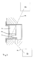
- FIG. 3 an advantageous front-side arrangement of the device 3 is shown in a receiving space 17 of the device base 6.
- a removable cover (not shown) closes this receiving space 17, in which the device 3 can be positively inserted and latched in a form-locking manner.
- the connection contacts 16 are guided protected against contact from the device 3, which are electrically contacted with the terminals 9 in the device base 6.
- the front element 8 and then the cover of the receiving space 17 is removed. Due to the positive connection and a cylindrical spatial extension, the device 3 can be pushed linearly without tilting up to the stop in the circular segment-shaped receiving space 17. It is automatically mechanically locked as well as electrically connected to the mains voltage. On the upper side of the device 3 are lighting elements to light signals targeted To be able to direct display elements in the front element 8. Finally, the front element 8 is mounted again. In this embodiment, neither an expansion of the installation device 2 nor additional connection work is necessary.
Landscapes
- Engineering & Computer Science (AREA)
- Microelectronics & Electronic Packaging (AREA)
- Details Of Indoor Wiring (AREA)
- Casings For Electric Apparatus (AREA)
Applications Claiming Priority (1)
| Application Number | Priority Date | Filing Date | Title |
|---|---|---|---|
| DE102007063586A DE102007063586A1 (de) | 2007-12-21 | 2007-12-21 | Installationsanordnung |
Publications (2)
| Publication Number | Publication Date |
|---|---|
| EP2073322A2 true EP2073322A2 (fr) | 2009-06-24 |
| EP2073322A3 EP2073322A3 (fr) | 2011-03-30 |
Family
ID=40474199
Family Applications (1)
| Application Number | Title | Priority Date | Filing Date |
|---|---|---|---|
| EP08021989A Ceased EP2073322A3 (fr) | 2007-12-21 | 2008-12-18 | Agencement d'installation |
Country Status (2)
| Country | Link |
|---|---|
| EP (1) | EP2073322A3 (fr) |
| DE (1) | DE102007063586A1 (fr) |
Families Citing this family (1)
| Publication number | Priority date | Publication date | Assignee | Title |
|---|---|---|---|---|
| DE102010022725A1 (de) * | 2010-06-04 | 2011-12-08 | Hans-Dieter Leibold | Analysevorrichtung für Stromverbraucher |
Citations (1)
| Publication number | Priority date | Publication date | Assignee | Title |
|---|---|---|---|---|
| EP0281969B1 (fr) | 1987-03-10 | 1994-02-09 | Asea Brown Boveri Aktiengesellschaft | Prise de courant à module supplémentaire |
Family Cites Families (8)
| Publication number | Priority date | Publication date | Assignee | Title |
|---|---|---|---|---|
| US6160728A (en) * | 1999-05-26 | 2000-12-12 | Advanced Micro Devices, Inc. | Dual-mode AC/DC electrical receptacle |
| US6993289B2 (en) * | 2000-08-02 | 2006-01-31 | Simple Devices | System including a wall switch device and a system including a power outlet device and methods for using the same |
| US6993417B2 (en) * | 2001-09-10 | 2006-01-31 | Osann Jr Robert | System for energy sensing analysis and feedback |
| DE602004026108D1 (de) * | 2003-11-07 | 2010-04-29 | Mpathx Llc | Automatische mess-leistungssysteme und verfahren |
| ATE350785T1 (de) * | 2004-02-02 | 2007-01-15 | Alombard Sas | Elektrische anschlussklemme und anwendung in einer steckdose |
| DE102005010949A1 (de) * | 2005-03-10 | 2006-09-14 | Abb Patent Gmbh | System zur Freigabe eines elektrischen Installationsgerätes |
| EP1929591A4 (fr) * | 2005-09-02 | 2013-04-03 | Kim Sun Young | Socle de fiche a coupure automatique de courant de reserve |
| DE202005015140U1 (de) * | 2005-09-24 | 2005-12-08 | Kleinknecht Systemtechnik Gmbh | Elektrische Steckdose oder elektrischer Schalter |
-
2007
- 2007-12-21 DE DE102007063586A patent/DE102007063586A1/de not_active Ceased
-
2008
- 2008-12-18 EP EP08021989A patent/EP2073322A3/fr not_active Ceased
Patent Citations (1)
| Publication number | Priority date | Publication date | Assignee | Title |
|---|---|---|---|---|
| EP0281969B1 (fr) | 1987-03-10 | 1994-02-09 | Asea Brown Boveri Aktiengesellschaft | Prise de courant à module supplémentaire |
Also Published As
| Publication number | Publication date |
|---|---|
| EP2073322A3 (fr) | 2011-03-30 |
| DE102007063586A1 (de) | 2009-07-02 |
Similar Documents
| Publication | Publication Date | Title |
|---|---|---|
| EP2057718B1 (fr) | Systeme d'energie a rail | |
| DE29912331U1 (de) | Elektrischer Vielzweck-Verbinder | |
| DE102010007502A1 (de) | Elektrisches Unterputz-Installationsgerät zur Aufnahme eines mobilen Audio- und Kommunikationsgerätes | |
| EP3744159B1 (fr) | Connecteur enfichable et dispositif électronique | |
| EP3176878B1 (fr) | Boîte de connexion de câbles et module de protection contre les surtensions pour une boîte de connexion de câbles | |
| EP2073322A2 (fr) | Agencement d'installation | |
| EP3671976A1 (fr) | Dispositif de raccordement enfichable électrique et appareil électrique associé | |
| EP2253047B1 (fr) | Bloc de raccordement à fonctions extensibles et module | |
| EP2073321B1 (fr) | Appareil d'installation | |
| DE202014100207U1 (de) | Koppler für Mittelspannungs-Powerline-Communication | |
| DE102007063584B4 (de) | Elektrisches Installationsgerät | |
| DE102010040595A1 (de) | Verbindungssystem sowie Aufnahmeeinheit für ein Steuergerät | |
| DE2616392C2 (de) | Geräteeinsatz der elektrischen Nachrichtenübertragungstechnik | |
| EP2351176B1 (fr) | Boîte d'installation électrique | |
| EP4070985A1 (fr) | Unité électrique de commande de puissance et station de charge | |
| DE202011000284U1 (de) | Funktionsüberprüfungseinrichtung für Photovoltaikanlagen | |
| EP2315319A1 (fr) | Prise électrique à contact protégé | |
| DE202014000549U1 (de) | Netzwerkzugangsvorrichtung | |
| DE102009008905A1 (de) | Anschlußdose, Endgerät und Signalübertragungsvorrichtung | |
| DE202013008312U1 (de) | Gefahrenmelderzentrale mit integrierter KNX-Busschnittstelle | |
| EP2214416B1 (fr) | Patch-Panel ainsi que son procédé d'installation | |
| DE20311394U1 (de) | Schutzvorrichtung | |
| DE2635336C2 (de) | Verdrahtung von tragbaren Geräten der Funkortungstechnik | |
| DE102022120668A1 (de) | Auslesevorrichtung zum Auslesen von Daten eines Verbrauchszählers | |
| DE102018106003A1 (de) | Anschlussklemme |
Legal Events
| Date | Code | Title | Description |
|---|---|---|---|
| PUAI | Public reference made under article 153(3) epc to a published international application that has entered the european phase |
Free format text: ORIGINAL CODE: 0009012 |
|
| AK | Designated contracting states |
Kind code of ref document: A2 Designated state(s): AT BE BG CH CY CZ DE DK EE ES FI FR GB GR HR HU IE IS IT LI LT LU LV MC MT NL NO PL PT RO SE SI SK TR |
|
| AX | Request for extension of the european patent |
Extension state: AL BA MK RS |
|
| PUAL | Search report despatched |
Free format text: ORIGINAL CODE: 0009013 |
|
| AK | Designated contracting states |
Kind code of ref document: A3 Designated state(s): AT BE BG CH CY CZ DE DK EE ES FI FR GB GR HR HU IE IS IT LI LT LU LV MC MT NL NO PL PT RO SE SI SK TR |
|
| AX | Request for extension of the european patent |
Extension state: AL BA MK RS |
|
| 17P | Request for examination filed |
Effective date: 20110914 |
|
| AKX | Designation fees paid |
Designated state(s): AT BE BG CH CY CZ DE DK EE ES FI FR GB GR HR HU IE IS IT LI LT LU LV MC MT NL NO PL PT RO SE SI SK TR |
|
| 17Q | First examination report despatched |
Effective date: 20120302 |
|
| APBK | Appeal reference recorded |
Free format text: ORIGINAL CODE: EPIDOSNREFNE |
|
| APBN | Date of receipt of notice of appeal recorded |
Free format text: ORIGINAL CODE: EPIDOSNNOA2E |
|
| APBR | Date of receipt of statement of grounds of appeal recorded |
Free format text: ORIGINAL CODE: EPIDOSNNOA3E |
|
| APAF | Appeal reference modified |
Free format text: ORIGINAL CODE: EPIDOSCREFNE |
|
| PUAJ | Public notification under rule 129 epc |
Free format text: ORIGINAL CODE: 0009425 |
|
| 32PN | Public notification |
Free format text: LADUNG ZUR MUENDLICHEN VERHANDLUNG |
|
| APBT | Appeal procedure closed |
Free format text: ORIGINAL CODE: EPIDOSNNOA9E |
|
| STAA | Information on the status of an ep patent application or granted ep patent |
Free format text: STATUS: THE APPLICATION HAS BEEN REFUSED |
|
| 18R | Application refused |
Effective date: 20201008 |