EP2073358A2 - Compact actuator - Google Patents
Compact actuator Download PDFInfo
- Publication number
- EP2073358A2 EP2073358A2 EP20080105625 EP08105625A EP2073358A2 EP 2073358 A2 EP2073358 A2 EP 2073358A2 EP 20080105625 EP20080105625 EP 20080105625 EP 08105625 A EP08105625 A EP 08105625A EP 2073358 A2 EP2073358 A2 EP 2073358A2
- Authority
- EP
- European Patent Office
- Prior art keywords
- rotor
- sun gear
- gear
- actuator according
- teeth
- Prior art date
- Legal status (The legal status is an assumption and is not a legal conclusion. Google has not performed a legal analysis and makes no representation as to the accuracy of the status listed.)
- Withdrawn
Links
Images
Classifications
-
- H—ELECTRICITY
- H02—GENERATION; CONVERSION OR DISTRIBUTION OF ELECTRIC POWER
- H02K—DYNAMO-ELECTRIC MACHINES
- H02K7/00—Arrangements for handling mechanical energy structurally associated with dynamo-electric machines, e.g. structural association with mechanical driving motors or auxiliary dynamo-electric machines
- H02K7/10—Structural association with clutches, brakes, gears, pulleys or mechanical starters
- H02K7/116—Structural association with clutches, brakes, gears, pulleys or mechanical starters with gears
-
- H—ELECTRICITY
- H02—GENERATION; CONVERSION OR DISTRIBUTION OF ELECTRIC POWER
- H02K—DYNAMO-ELECTRIC MACHINES
- H02K21/00—Synchronous motors having permanent magnets; Synchronous generators having permanent magnets
- H02K21/12—Synchronous motors having permanent magnets; Synchronous generators having permanent magnets with stationary armatures and rotating magnets
- H02K21/14—Synchronous motors having permanent magnets; Synchronous generators having permanent magnets with stationary armatures and rotating magnets with magnets rotating within the armatures
Definitions
- the present invention relates to a compact actuator according to the preamble of claim 1.
- Actuators are known from the prior art in different configurations. Actuators are used for example in vehicles as wiper motors, Wegverstellmotoren or window regulator motors. Due to the often cramped space conditions, it is desirable that such actuators are designed as small as possible. The problem here is that due to the high speeds of the electric motors for the applications in each case a reduction gear must be installed. However, this increases the size of the engine-transmission units.
- the actuator according to the invention with the features of claim 1 has the advantage over that it takes up a minimal space and yet it is very simple and inexpensive. Furthermore, according to the invention, a multi-stage reduction gear can be provided, so that the actuator according to the invention can be used in particular as a small actuator in vehicles.
- the actuator designed as a hollow shaft with internal teeth rotor than Input element of a planetary gear includes. Inside the hollow rotor then the planetary gear with multiple planets and a planet carrier and at least one sun gear is arranged. The internal toothing of the rotor forms the ring gear of the planetary gear. Thus, the rotor is an integral part of the planetary gear. This allows a very compact design for the actuator can be realized.
- a plurality of permanent magnets are further arranged on the circumference of the rotor. This allows the electric machine to be designed as EC motor. Without permanent magnets, an SR motor or a switched reluctance machine can be provided.
- exactly one sun gear is provided, which is arranged stationary.
- An output of the planetary gear takes place via a planet carrier.
- the sun gear which is fixed in place, for example, on a housing, additionally assumes a bearing function for the planetary gear. In this case, no separate bearing components are to be provided for the rotor and the planet or the planet carrier.
- the planetary gear comprises a first sun gear and a second sun gear. Both sun gears mesh with the planet gears, wherein the first sun gear is arranged stationary and the second sun gear is rotatably arranged. An output of the planetary gear via the second, rotatable sun gear.
- This structure makes it possible for a compact and simple output to take place via, for example, an output shaft fixed to the second sun gear.
- a bearing of the second sun gear as well as the rotor, can be done via the planetary gears and the stationary first sun gear. This allows the actuator to provide a particularly simple and compact design.
- a number of teeth of the stationary first sun gear is greater than a number of teeth of the second rotatable sun gear.
- the number of teeth of the second rotatable sun gear equal to a number of teeth of the first stationary Sun gear minus or plus the number of existing planetary gears. That is, for example, if the first sun gear has a number of teeth of 30 and three planet gears are present, the second sun gear has a number of teeth of 27.
- the second sun gear has a number of teeth which is equal to a number of teeth of the first sun gear minus or in addition a multiple of the number of existing planetary gears. This ensures that the planets are always in contact with the first and second sun gears.
- the two sun gears can be realized with reversed numbers of teeth, for example, standing sun gear 27 teeth and rotating sun gear 30 teeth.
- the rotor is preferably made of a laminated core.
- the rotor is produced by means of stamping and an internal toothing of the rotor is carried out simultaneously with the punching process in several or all sheets.
- the individual sheets can be connected to each other for example by gluing or by riveting or via positive connections between the individual sheets.
- a number of the planetary gears of the planetary gear according to the invention is preferably 3 or 4. In this way, on the one hand a sufficient reduction can be ensured and on the other hand, the number of parts of the planetary gear is not too large.
- magnets which are arranged in the rotor, magnets are preferably used from a rare earth material.
- permanent magnets made of NdFeB are used here, whereby a remanent induction, e.g. compared to ferrite, can be significantly increased by about a factor of 3.
- the actuator is preferably used in vehicles as a wiper drive or as a window lift drive or Wegverstellantrieb or Schiebedachverstellantrieb.
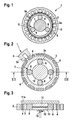
- FIG. 1 an actuator 1 according to a first preferred embodiment of the invention described in detail.
- the actuator 1 comprises a stator 2 with a plurality of poles 2a, on each of which a winding (not shown) is provided.
- a rotor 3 is arranged, which is designed as a hollow rotor. Inside the hollow rotor, an internal toothing 3a is provided.
- a plurality of permanent magnets 4 are arranged along the circumference. In this embodiment, the permanent magnets 4 are fixed by means of gluing on the rotor 3.
- the permanent magnets are made of a rare earth material.
- a planetary gear 5 is arranged inside the hollow rotor.
- the internal gear 3a of the rotor 3 forms the ring gear of the planetary gear 5.
- the planetary gear 5 comprises three planet gears 6 and a sun gear 7.
- the sun gear 7 is arranged centrally in the rotor 3 and arranged stationary on a housing of the actuator. By means of this structure, it is possible in particular to dispense with a separate mounting of the rotor 3.
- the rotor 3 is guided and supported in this embodiment via the three planet gears.
- An output of the planetary gear is provided via a planet carrier, not shown.
- a motor and a transmission of the actuator 1 is a compact unit, wherein the planetary gear 5 is integrated directly in the interior of the hollow rotor.
- the rotor is part of the planetary gear.
- the actuator still has a very simple and inexpensive construction.
- the motor can be used in particular where small speeds and high torque requirements, such as window regulators or sunroof drives, are required.
- the rotor 3 is formed from a stamped laminated core, wherein the laminated core comprises a plurality of stamped individual sheets.
- the laminated core comprises a plurality of stamped individual sheets.
- a deburring step is additionally carried out after the punching process, in particular in the region of the internal toothing, as a result of which a service life of the rotor can be significantly increased.
- the individual sheets are joined together via positive connection elements to the laminated core.
- FIGS. 2 and 3 an actuator 1 according to a second embodiment of the invention described in detail.
- the same or functionally identical parts are denoted by the same reference numerals as in the first embodiment.
- FIGS. 2 and 3 only the rotor is shown schematically together with the integrated planetary gear.
- a stator 2 is, as in the in FIG. 1 shown embodiment, constructed.
- FIG. 2 in contrast to the first embodiment in the second embodiment, the permanent magnets 4 are integrated into the rotor 3 and disposed slightly within the outer periphery of the rotor 3.
- the rotor made of a plurality of sheets on punched recesses for receiving the permanent magnets 4.
- the planetary gear 5 has four planet wheels 6.
- a first sun gear 11 and a second sun gear 12 are provided.
- the two sun gears 11 and 12 are arranged on an axis one behind the other, wherein, however, the first sun gear 11 via a mounting plate 11a with a housing of the actuator (not shown) is connected.
- the second sun gear 12 is connected to an output shaft 10.
- the first sun gear 11 is stationary arranged and the second sun gear 12 is rotatably arranged. In the axial direction, a gap 13 between the first and second sun gear 11, 12 is present.
- a number of teeth of the sun gears is selected such that the second rotatable sun gear 12 has a number of teeth equal to the number of teeth of the first fixed sun gear 11 minus the number of planets 6. That is, when the first sun gear 11 has a number of teeth of 84 and four planetary gears 6 are provided, the rotatable second sun gear 12 has a number of teeth of 80.
- the rotor 3 can be supported via the planet gears 6. Furthermore, the four planet gears 6 can also support the rotatable sun gear 12. Since the stationary first sun gear 11 supports the planet 6, it is not absolutely necessary to provide a planet carrier, but the planet gears 6 can be arranged freely between the internal teeth 3 a and the sun gears 11, 12.
- a support of a differential torque with respect to the housing is taken over the first stationary sun gear 11 during operation.
- an actuator can thus be provided in which a planetary gear is integrated in a hollow rotor shaft of an electric drive.
- a planetary gear is integrated in a hollow rotor shaft of an electric drive.
- the internal toothing of the rotor can also be made of a different material than the laminated core. It is also also possible to store the rotating parts of the drive, such as the rotor and the gears, separately.
Landscapes
- Engineering & Computer Science (AREA)
- Power Engineering (AREA)
- Connection Of Motors, Electrical Generators, Mechanical Devices, And The Like (AREA)
- Retarders (AREA)
Abstract
Description
Die vorliegende Erfindung betrifft einen kompakten Stellantrieb gemäß dem Oberbegriff des Anspruches 1.The present invention relates to a compact actuator according to the preamble of claim 1.
Stellantriebe sind aus dem Stand der Technik in unterschiedlichen Ausgestaltungen bekannt. Stellantriebe werden beispielsweise in Fahrzeugen als Wischermotoren, Sitzverstellmotoren oder Fensterhebermotoren verwendet. Aufgrund der häufig beengten Platzverhältnisse ist es wünschenswert, dass derartige Stellantriebe möglichst kleinbauend ausgelegt sind. Problematisch hierbei ist, dass aufgrund der hohen Drehzahlen der Elektromotoren für die Anwendungsfälle jeweils noch ein Untersetzungsgetriebe eingebaut werden muss. Hierbei vergrößern sich jedoch die Abmessungen der Motor-Getriebe-Einheiten.Actuators are known from the prior art in different configurations. Actuators are used for example in vehicles as wiper motors, Sitzverstellmotoren or window regulator motors. Due to the often cramped space conditions, it is desirable that such actuators are designed as small as possible. The problem here is that due to the high speeds of the electric motors for the applications in each case a reduction gear must be installed. However, this increases the size of the engine-transmission units.
Aus der
Der erfindungsgemäße Stellantrieb mit den Merkmalen des Patentanspruchs 1 weist demgegenüber den Vorteil auf, dass er einen minimalen Bauraum aufnimmt und dabei trotzdem sehr einfach und kostengünstig aufgebaut ist. Ferner kann erfindungsgemäß auch ein mehrstufiges Untersetzungsgetriebe bereitgestellt werden, so dass der erfindungsgemäße Stellantrieb insbesondere auch in Fahrzeugen als kleiner Stellantrieb verwendet werden kann. Dies wird erfindungsgemäß dadurch erreicht, dass der Stellantrieb einen als Hohlwelle mit einer Innenverzahnung ausgebildeten Rotor als Eingangselement eines Planetengetriebes umfasst. Im Inneren des hohlen Rotors ist dann das Planetengetriebe mit mehreren Planeten und einem Planetenradträger sowie wenigstens einem Sonnenrad angeordnet. Die Innenverzahnung des Rotors bildet das Hohlrad des Planetengetriebes. Somit ist der Rotor integraler Bestandteil des Planetengetriebes. Dadurch kann ein sehr kompakter Aufbau für den Stellantrieb realisiert werden.The actuator according to the invention with the features of claim 1 has the advantage over that it takes up a minimal space and yet it is very simple and inexpensive. Furthermore, according to the invention, a multi-stage reduction gear can be provided, so that the actuator according to the invention can be used in particular as a small actuator in vehicles. This is inventively achieved in that the actuator designed as a hollow shaft with internal teeth rotor than Input element of a planetary gear includes. Inside the hollow rotor then the planetary gear with multiple planets and a planet carrier and at least one sun gear is arranged. The internal toothing of the rotor forms the ring gear of the planetary gear. Thus, the rotor is an integral part of the planetary gear. This allows a very compact design for the actuator can be realized.
Die Unteransprüche zeigen bevorzugte Weiterbildungen der Erfindung.The dependent claims show preferred developments of the invention.
Bevorzugt sind am Umfang des Rotors ferner eine Vielzahl von Permanentmagneten angeordnet. Hierdurch kann die elektrische Maschine als EC-Motor ausgebildet sein. Ohne Permanentmagnete kann ein SR-Motor bzw. eine geschaltete Reluktanzmaschine bereitgestellt werden.Further, a plurality of permanent magnets are further arranged on the circumference of the rotor. This allows the electric machine to be designed as EC motor. Without permanent magnets, an SR motor or a switched reluctance machine can be provided.
Vorzugsweise ist genau ein Sonnenrad vorgesehen, welches ortsfest angeordnet ist. Ein Abtrieb des Planetengetriebes erfolgt dabei über einen Planetenradträger. Hierdurch übernimmt das Sonnenrad, welches beispielsweise an einem Gehäuse ortsfest fixiert ist, zusätzlich noch eine Lagerfunktion für das Planetengetriebe. Hierbei sind für den Rotor und die Planeten- bzw. den Planetenradträger keine separaten Lagerbauteile vorzusehen.Preferably, exactly one sun gear is provided, which is arranged stationary. An output of the planetary gear takes place via a planet carrier. As a result, the sun gear, which is fixed in place, for example, on a housing, additionally assumes a bearing function for the planetary gear. In this case, no separate bearing components are to be provided for the rotor and the planet or the planet carrier.
Gemäß einer alternativen Ausgestaltung der vorliegenden Erfindung umfasst das Planetengetriebe ein erstes Sonnenrad und ein zweites Sonnenrad. Beide Sonnenräder kämmen dabei mit den Planetenrädern, wobei das erste Sonnenrad ortsfest angeordnet ist und das zweite Sonnenrad drehbar angeordnet ist. Ein Abtrieb des Planetengetriebes erfolgt über das zweite, drehbare Sonnenrad. Dieser Aufbau ermöglicht es, dass ein kompakter und einfacher Abtrieb über beispielsweise eine am zweiten Sonnenrad fixierte Abtriebswelle erfolgen kann. Eine Lagerung des zweiten Sonnenrads sowie auch des Rotors, kann dabei über die Planetenräder und das ortsfeste erste Sonnenrad erfolgen. Dadurch kann der Stellantrieb einen besonders einfachen und kompakten Aufbau bereitstellen.According to an alternative embodiment of the present invention, the planetary gear comprises a first sun gear and a second sun gear. Both sun gears mesh with the planet gears, wherein the first sun gear is arranged stationary and the second sun gear is rotatably arranged. An output of the planetary gear via the second, rotatable sun gear. This structure makes it possible for a compact and simple output to take place via, for example, an output shaft fixed to the second sun gear. A bearing of the second sun gear as well as the rotor, can be done via the planetary gears and the stationary first sun gear. This allows the actuator to provide a particularly simple and compact design.
Vorzugsweise ist eine Zähnezahl des ortsfesten ersten Sonnenrads größer als eine Zähnezahl des zweiten drehbaren Sonnenrads. Besonders bevorzugt ist dabei die Zähnezahl des zweiten drehbaren Sonnenrads gleich einer Zähnezahl des ersten ortsfesten Sonnenrads abzüglich oder zuzüglich der Anzahl der vorhandenen Planetenräder. D.h., wenn z.B. das erste Sonnenrad eine Zähnezahl von 30 aufweist und drei Planetenräder vorhanden sind, weist das zweite Sonnenrad einen Zähnezahl von 27 auf. Alternativ weist das zweite Sonnenrad eine Zähnezahl auf, welche gleich einer Zähnezahl des ersten Sonnenrads abzüglich oder zuzüglich eines Vielfachen der Anzahl der vorhandenen Planetenräder ist. Hierdurch wird gewährleistet, dass die Planeten immer in Kontakt mit dem ersten und zweiten Sonnenrad sind. Selbstverständlich lassen sich die beiden Sonnenräder auch mit umgekehrten Zahnzahlen realisieren, z.B. stehendes Sonnenrad 27 Zähne und drehendes Sonnenrad 30 Zähne.Preferably, a number of teeth of the stationary first sun gear is greater than a number of teeth of the second rotatable sun gear. Particularly preferred is the number of teeth of the second rotatable sun gear equal to a number of teeth of the first stationary Sun gear minus or plus the number of existing planetary gears. That is, for example, if the first sun gear has a number of teeth of 30 and three planet gears are present, the second sun gear has a number of teeth of 27. Alternatively, the second sun gear has a number of teeth which is equal to a number of teeth of the first sun gear minus or in addition a multiple of the number of existing planetary gears. This ensures that the planets are always in contact with the first and second sun gears. Of course, the two sun gears can be realized with reversed numbers of teeth, for example, standing sun gear 27 teeth and rotating sun gear 30 teeth.
Um eine besonders einfache und kostengünstige Herstellbarkeit des Stellantriebs zu gewährleisten, ist der Rotor vorzugsweise aus einem Blechpaket hergestellt. Besonders bevorzugt wird der Rotor dabei mittels Stanzen hergestellt und eine Innenverzahnung des Rotors wird gleichzeitig mit dem Stanzvorgang in mehreren oder allen Blechen vorgenommen. Die einzelnen Bleche können beispielsweise mittels Kleben oder mittels Nieten oder über formschlüssige Verbindungen zwischen den einzelnen Blechen miteinander verbunden werden.In order to ensure a particularly simple and cost-effective manufacturability of the actuator, the rotor is preferably made of a laminated core. Particularly preferably, the rotor is produced by means of stamping and an internal toothing of the rotor is carried out simultaneously with the punching process in several or all sheets. The individual sheets can be connected to each other for example by gluing or by riveting or via positive connections between the individual sheets.
Eine Anzahl der Planetenräder des erfindungsgemäßen Planetengetriebes ist vorzugsweise 3 oder 4. Hierdurch kann einerseits eine ausreichende Untersetzung sichergestellt werden und andererseits wird die Teilezahl des Planetengetriebes nicht zu groß.A number of the planetary gears of the planetary gear according to the invention is preferably 3 or 4. In this way, on the one hand a sufficient reduction can be ensured and on the other hand, the number of parts of the planetary gear is not too large.
Als Permanentmagneten, welche im Rotor angeordnet sind, werden vorzugsweise Magneten aus einem Selten-Erden-Material verwendet. Hierbei werden insbesondere Permanentmagneten aus NdFeB verwendet, wodurch eine Remanenzinduktion, z.B. gegenüber Ferrit, signifikant um ca. den Faktor 3 vergrößert werden kann.As permanent magnets, which are arranged in the rotor, magnets are preferably used from a rare earth material. In particular, permanent magnets made of NdFeB are used here, whereby a remanent induction, e.g. compared to ferrite, can be significantly increased by about a factor of 3.
Der Stellantrieb wird vorzugsweise in Fahrzeugen als Wischerantrieb oder als Fensterheberantrieb oder als Sitzverstellantrieb oder Schiebedachverstellantrieb verwendet.The actuator is preferably used in vehicles as a wiper drive or as a window lift drive or Sitzverstellantrieb or Schiebedachverstellantrieb.
Nachfolgend werden bevorzugte Ausführungsbeispiele der Erfindung unter Bezugnahme auf die begleitende Zeichnung im Detail beschrieben. In der Zeichnung ist:
- Figur 1
- eine schematische Schnittansicht eines Stellantriebs gemäß einem ersten Ausführungsbeispiel der Erfindung,
Figur 2- eine schematische Schnittansicht eines Stellantriebs gemäß einem zweiten Ausführungsbeispiel der Erfindung, und
- Figur 3
- eine Schnittansicht entlang der Linie III-III von
Figur 2
- FIG. 1
- a schematic sectional view of an actuator according to a first embodiment of the invention,
- FIG. 2
- a schematic sectional view of an actuator according to a second embodiment of the invention, and
- FIG. 3
- a sectional view taken along the line III-III of
FIG. 2 ,
Nachfolgend wird unter Bezugnahme auf
Wie aus
Im Inneren des hohlen Rotors ist ein Planetengetriebe 5 angeordnet. Die Innenverzahnung 3a des Rotors 3 bildet dabei das Hohlrad des Planetengetriebes 5. Ferner umfasst das Planetengetriebe 5 drei Planetenräder 6 sowie ein Sonnenrad 7. Das Sonnenrad 7 ist zentrisch im Rotor 3 angeordnet und an einem Gehäuse des Stellantriebs ortsfest angeordnet. Durch diesen Aufbau kann insbesondere auf eine gesonderte Lagerung des Rotors 3 verzichtet werden. Der Rotor 3 ist in diesem Ausführungsbeispiel über die drei Planetenräder geführt und gelagert. Ein Abtrieb des Planetengetriebes ist über einen nicht dargestellten Planetenradträger vorgesehen. Durch den in
Somit bilden erfindungsgemäß ein Motor und ein Getriebe des Stellantriebs 1 eine kompakte Einheit, wobei das Planetengetriebe 5 direkt im Inneren des hohlen Rotors integriert ist. Der Rotor ist dabei ein Teil des Planetengetriebes. Dabei weist der Stellantrieb trotzdem einen sehr einfachen und kostengünstigen Aufbau auf. Der Motor kann insbesondere dort eingesetzt werden, wo kleine Geschwindigkeiten und hohe Momentanforderungen, wie beispielsweise bei Fensterhebern oder Schiebedachantrieben, verlangt werden.Thus, according to the invention form a motor and a transmission of the actuator 1 is a compact unit, wherein the
Der Rotor 3 ist aus einem gestanzten Blechpaket gebildet, wobei das Blechpaket eine Vielzahl von gestanzten Einzelblechen umfasst. Beim Stanzen wird dabei die Innenverzahnung mit ausgestanzt, so dass der Rotor sehr kostengünstig hergestellt werden kann. Um einen erhöhten Verschleiß am Rotor zu vermeiden, wird nach dem Stanzvorgang insbesondere im Bereich der Innenverzahnung zusätzlich noch ein Entgratungsschritt ausgeführt, wodurch eine Lebensdauer des Rotors signifikant vergrößert werden kann. Die einzelnen Bleche sind dabei über formschlüssige Verbindungselemente zu dem Blechpaket zusammengefügt.The rotor 3 is formed from a stamped laminated core, wherein the laminated core comprises a plurality of stamped individual sheets. When punching the internal teeth is punched out, so that the rotor can be made very inexpensive. In order to avoid increased wear on the rotor, a deburring step is additionally carried out after the punching process, in particular in the region of the internal toothing, as a result of which a service life of the rotor can be significantly increased. The individual sheets are joined together via positive connection elements to the laminated core.
Nachfolgend wird unter Bezugnahme auf die
In den
Wie aus
Eine Zähnezahl der Sonnenräder ist derart gewählt, dass das zweite, drehbare Sonnenrad 12 eine Zähnezahl aufweist, welche gleich der Zähnezahl des ersten, ortsfesten Sonnenrads 11 abzüglich der Anzahl der Planeten 6 ist. D.h., wenn das erste Sonnenrad 11 eine Zähnezahl von 84 aufweist und vier Planetenräder 6 vorgesehen sind, weist das drehbare zweite Sonnenrad 12 eine Zähnezahl von 80 auf.A number of teeth of the sun gears is selected such that the second
Da das erste Sonnenrad 11 ortsfest ist, kann ferner der Rotor 3 über die Planetenräder 6 gelagert werden. Ferner können die vier Planetenräder 6 auch das drehbare Sonnenrad 12 lagern. Da das ortsfeste erste Sonnenrad 11 die Planeten 6 lagert, ist es nicht zwingend notwendig, einen Planetenradträger vorzusehen, sondern die Planetenräder 6 können frei zwischen der Innenverzahnung 3 a und den Sonnenrädern 11, 12 angeordnet sein.Further, since the
Da der Eingang des Planetengetriebes der hohle Rotor 3 ist, wird eine zweistufige Untersetzung bereitgestellt, wobei insbesondere eine Gesamtübersetzung von bis zu 1 : 27 erreicht werden kann. Ferner lassen sich, je nach Abmessungen und Zahnzahlen der Betriebsräder, auch Übersetzungen größer als 27 und kleiner als 27 realisieren.Since the input of the planetary gear is the hollow rotor 3, a two-stage reduction is provided, in particular, a total ratio of up to 1:27 can be achieved. Furthermore, depending on the dimensions and numbers of teeth of the operating wheels, also translations larger than 27 and smaller than 27 can be realized.
Ferner wird über das erste, ortsfeste Sonnenrad 11 während des Betriebes eine Abstützung eines Differenzmoments gegenüber dem Gehäuse übernommen.Furthermore, a support of a differential torque with respect to the housing is taken over the first
Ansonsten entspricht dieses Ausführungsbeispiel dem vorhergehenden Ausführungsbeispiel, so dass auf die dort gegebene Beschreibung verwiesen werden kann.Otherwise, this embodiment corresponds to the previous embodiment, so that reference can be made to the description given there.
Erfindungsgemäß kann somit ein Stellantrieb bereitgestellt werden, bei dem ein Planetengetriebe in eine hohle Rotorwelle eines elektrischen Antriebes integriert ist. Hierdurch ergibt sich ein kompakter und einfacher Aufbau, da insbesondere ein Eingang in das Planetengetriebe über den hohlen Rotor 3 realisiert ist, welcher als Hohlrad des Planetengetriebes fungiert.According to the invention, an actuator can thus be provided in which a planetary gear is integrated in a hollow rotor shaft of an electric drive. This results in a compact and simple construction, since in particular an input is realized in the planetary gear via the hollow rotor 3, which acts as a ring gear of the planetary gear.
Bei höheren Anforderungen an Lebensdauer und Momente kann die Innenverzahnung des Rotors auch aus einem anderen Werkstoff als dem Blechpaket eingesetzt werden. Zudem ist es auch möglich, die rotierenden Teile des Antriebes, wie z.B. den Rotor und die Zahnräder, separat zu lagern.For higher life and torque requirements, the internal toothing of the rotor can also be made of a different material than the laminated core. It is also also possible to store the rotating parts of the drive, such as the rotor and the gears, separately.
Claims (10)
Applications Claiming Priority (1)
| Application Number | Priority Date | Filing Date | Title |
|---|---|---|---|
| DE200710060950 DE102007060950A1 (en) | 2007-12-18 | 2007-12-18 | Compact actuator |
Publications (1)
| Publication Number | Publication Date |
|---|---|
| EP2073358A2 true EP2073358A2 (en) | 2009-06-24 |
Family
ID=40394326
Family Applications (1)
| Application Number | Title | Priority Date | Filing Date |
|---|---|---|---|
| EP20080105625 Withdrawn EP2073358A2 (en) | 2007-12-18 | 2008-10-21 | Compact actuator |
Country Status (3)
| Country | Link |
|---|---|
| EP (1) | EP2073358A2 (en) |
| CN (1) | CN101465577A (en) |
| DE (1) | DE102007060950A1 (en) |
Cited By (5)
| Publication number | Priority date | Publication date | Assignee | Title |
|---|---|---|---|---|
| WO2013189649A1 (en) * | 2012-06-18 | 2013-12-27 | Robert Bosch Gmbh | Electric motor with planetary gear unit |
| US8834311B1 (en) * | 2013-03-07 | 2014-09-16 | The United States Of America As Represented By The Secretary Of The Army | Concentric electric servomotor/gearbox drive |
| DE102013211301A1 (en) | 2013-06-17 | 2014-12-18 | Robert Bosch Gmbh | driving means |
| EP2553234A4 (en) * | 2010-03-31 | 2016-07-06 | Rotrex As | An electrically assisted turbocharger |
| CN110971075A (en) * | 2018-09-29 | 2020-04-07 | 上海鸣志电器股份有限公司 | An integrated motor structure |
Families Citing this family (2)
| Publication number | Priority date | Publication date | Assignee | Title |
|---|---|---|---|---|
| CN101934720B (en) * | 2009-06-30 | 2014-05-28 | 比亚迪股份有限公司 | Hybrid power driving system and driving method thereof |
| WO2025232929A1 (en) * | 2024-05-08 | 2025-11-13 | 上海爱动科技有限公司 | Rotor unit, primary planetary transmission structure, planetary-like transmission structure, speed reduction mechanism, geared motor, freewheel and power-assisted cycle |
Citations (1)
| Publication number | Priority date | Publication date | Assignee | Title |
|---|---|---|---|---|
| DE10243809A1 (en) | 2002-03-13 | 2004-05-19 | Robert Bosch Gmbh | actuator |
-
2007
- 2007-12-18 DE DE200710060950 patent/DE102007060950A1/en not_active Withdrawn
-
2008
- 2008-10-21 EP EP20080105625 patent/EP2073358A2/en not_active Withdrawn
- 2008-12-18 CN CNA2008101859854A patent/CN101465577A/en active Pending
Patent Citations (1)
| Publication number | Priority date | Publication date | Assignee | Title |
|---|---|---|---|---|
| DE10243809A1 (en) | 2002-03-13 | 2004-05-19 | Robert Bosch Gmbh | actuator |
Cited By (5)
| Publication number | Priority date | Publication date | Assignee | Title |
|---|---|---|---|---|
| EP2553234A4 (en) * | 2010-03-31 | 2016-07-06 | Rotrex As | An electrically assisted turbocharger |
| WO2013189649A1 (en) * | 2012-06-18 | 2013-12-27 | Robert Bosch Gmbh | Electric motor with planetary gear unit |
| US8834311B1 (en) * | 2013-03-07 | 2014-09-16 | The United States Of America As Represented By The Secretary Of The Army | Concentric electric servomotor/gearbox drive |
| DE102013211301A1 (en) | 2013-06-17 | 2014-12-18 | Robert Bosch Gmbh | driving means |
| CN110971075A (en) * | 2018-09-29 | 2020-04-07 | 上海鸣志电器股份有限公司 | An integrated motor structure |
Also Published As
| Publication number | Publication date |
|---|---|
| CN101465577A (en) | 2009-06-24 |
| DE102007060950A1 (en) | 2009-06-25 |
Similar Documents
| Publication | Publication Date | Title |
|---|---|---|
| DE102012212268B4 (en) | Drive system for an electric axle with two-speed gearbox | |
| DE102017211881A1 (en) | Drive device for driving an electrical axis | |
| DE19841159A1 (en) | Drive arrangement for a motor vehicle | |
| EP2073358A2 (en) | Compact actuator | |
| WO2014008897A1 (en) | Mounting concept for an electric axle | |
| DE102017011387A1 (en) | Electric drive device for a motor vehicle | |
| DE102016220630A1 (en) | Drive device for driving an electrical axis | |
| EP3493370B1 (en) | Drive device and axle drive device for a motor vehicle | |
| CH702879A2 (en) | Planetary gear in Wolf Roman order and Elekromotor with integrated planetary gear in Wolf Roman order. | |
| DE102011114322A1 (en) | Axis direct drive device for motor vehicle, has crown wheel differential having input wheels such as spur gears which are arranged between and meshed with coaxial axle flange wheels coaxial to internal rotor | |
| DE102021208036A1 (en) | Electric drive for a vehicle | |
| DE102019124666B4 (en) | Differential gear | |
| DE102004052562B3 (en) | Motor vehicle steering with superposition gear | |
| WO2019141561A1 (en) | Transmission for a motor vehicle, motor vehicle drive train, and method for operating same | |
| EP2066919B1 (en) | Multi-speed reduction gear | |
| WO2021074306A1 (en) | Electric drive for a vehicle | |
| DE102013211801B4 (en) | Electromechanical actuator | |
| DE102019103242A1 (en) | Electric drive device for a motor vehicle | |
| DE102018101597A1 (en) | Powertrain for a means of transport | |
| WO2014044277A1 (en) | Gear assembly | |
| WO2021089084A1 (en) | Hybrid transmission and hybrid drive arrangement | |
| DE102020200476A1 (en) | Electric drive for a vehicle | |
| DE102019207784A1 (en) | Electric drive for a vehicle in a housing | |
| DE102013211812B4 (en) | Planetary gear | |
| WO2013013950A2 (en) | Geared motor |
Legal Events
| Date | Code | Title | Description |
|---|---|---|---|
| PUAI | Public reference made under article 153(3) epc to a published international application that has entered the european phase |
Free format text: ORIGINAL CODE: 0009012 |
|
| AK | Designated contracting states |
Kind code of ref document: A2 Designated state(s): AT BE BG CH CY CZ DE DK EE ES FI FR GB GR HR HU IE IS IT LI LT LU LV MC MT NL NO PL PT RO SE SI SK TR |
|
| AX | Request for extension of the european patent |
Extension state: AL BA MK RS |
|
| STAA | Information on the status of an ep patent application or granted ep patent |
Free format text: STATUS: THE APPLICATION IS DEEMED TO BE WITHDRAWN |
|
| 18D | Application deemed to be withdrawn |
Effective date: 20130503 |