EP2073358A2 - Mécanisme de commande compact - Google Patents
Mécanisme de commande compact Download PDFInfo
- Publication number
- EP2073358A2 EP2073358A2 EP20080105625 EP08105625A EP2073358A2 EP 2073358 A2 EP2073358 A2 EP 2073358A2 EP 20080105625 EP20080105625 EP 20080105625 EP 08105625 A EP08105625 A EP 08105625A EP 2073358 A2 EP2073358 A2 EP 2073358A2
- Authority
- EP
- European Patent Office
- Prior art keywords
- rotor
- sun gear
- gear
- actuator according
- teeth
- Prior art date
- Legal status (The legal status is an assumption and is not a legal conclusion. Google has not performed a legal analysis and makes no representation as to the accuracy of the status listed.)
- Withdrawn
Links
Images
Classifications
-
- H—ELECTRICITY
- H02—GENERATION; CONVERSION OR DISTRIBUTION OF ELECTRIC POWER
- H02K—DYNAMO-ELECTRIC MACHINES
- H02K7/00—Arrangements for handling mechanical energy structurally associated with dynamo-electric machines, e.g. structural association with mechanical driving motors or auxiliary dynamo-electric machines
- H02K7/10—Structural association with clutches, brakes, gears, pulleys or mechanical starters
- H02K7/116—Structural association with clutches, brakes, gears, pulleys or mechanical starters with gears
-
- H—ELECTRICITY
- H02—GENERATION; CONVERSION OR DISTRIBUTION OF ELECTRIC POWER
- H02K—DYNAMO-ELECTRIC MACHINES
- H02K21/00—Synchronous motors having permanent magnets; Synchronous generators having permanent magnets
- H02K21/12—Synchronous motors having permanent magnets; Synchronous generators having permanent magnets with stationary armatures and rotating magnets
- H02K21/14—Synchronous motors having permanent magnets; Synchronous generators having permanent magnets with stationary armatures and rotating magnets with magnets rotating within the armatures
Definitions
- the present invention relates to a compact actuator according to the preamble of claim 1.
- Actuators are known from the prior art in different configurations. Actuators are used for example in vehicles as wiper motors, Wegverstellmotoren or window regulator motors. Due to the often cramped space conditions, it is desirable that such actuators are designed as small as possible. The problem here is that due to the high speeds of the electric motors for the applications in each case a reduction gear must be installed. However, this increases the size of the engine-transmission units.
- the actuator according to the invention with the features of claim 1 has the advantage over that it takes up a minimal space and yet it is very simple and inexpensive. Furthermore, according to the invention, a multi-stage reduction gear can be provided, so that the actuator according to the invention can be used in particular as a small actuator in vehicles.
- the actuator designed as a hollow shaft with internal teeth rotor than Input element of a planetary gear includes. Inside the hollow rotor then the planetary gear with multiple planets and a planet carrier and at least one sun gear is arranged. The internal toothing of the rotor forms the ring gear of the planetary gear. Thus, the rotor is an integral part of the planetary gear. This allows a very compact design for the actuator can be realized.
- a plurality of permanent magnets are further arranged on the circumference of the rotor. This allows the electric machine to be designed as EC motor. Without permanent magnets, an SR motor or a switched reluctance machine can be provided.
- exactly one sun gear is provided, which is arranged stationary.
- An output of the planetary gear takes place via a planet carrier.
- the sun gear which is fixed in place, for example, on a housing, additionally assumes a bearing function for the planetary gear. In this case, no separate bearing components are to be provided for the rotor and the planet or the planet carrier.
- the planetary gear comprises a first sun gear and a second sun gear. Both sun gears mesh with the planet gears, wherein the first sun gear is arranged stationary and the second sun gear is rotatably arranged. An output of the planetary gear via the second, rotatable sun gear.
- This structure makes it possible for a compact and simple output to take place via, for example, an output shaft fixed to the second sun gear.
- a bearing of the second sun gear as well as the rotor, can be done via the planetary gears and the stationary first sun gear. This allows the actuator to provide a particularly simple and compact design.
- a number of teeth of the stationary first sun gear is greater than a number of teeth of the second rotatable sun gear.
- the number of teeth of the second rotatable sun gear equal to a number of teeth of the first stationary Sun gear minus or plus the number of existing planetary gears. That is, for example, if the first sun gear has a number of teeth of 30 and three planet gears are present, the second sun gear has a number of teeth of 27.
- the second sun gear has a number of teeth which is equal to a number of teeth of the first sun gear minus or in addition a multiple of the number of existing planetary gears. This ensures that the planets are always in contact with the first and second sun gears.
- the two sun gears can be realized with reversed numbers of teeth, for example, standing sun gear 27 teeth and rotating sun gear 30 teeth.
- the rotor is preferably made of a laminated core.
- the rotor is produced by means of stamping and an internal toothing of the rotor is carried out simultaneously with the punching process in several or all sheets.
- the individual sheets can be connected to each other for example by gluing or by riveting or via positive connections between the individual sheets.
- a number of the planetary gears of the planetary gear according to the invention is preferably 3 or 4. In this way, on the one hand a sufficient reduction can be ensured and on the other hand, the number of parts of the planetary gear is not too large.
- magnets which are arranged in the rotor, magnets are preferably used from a rare earth material.
- permanent magnets made of NdFeB are used here, whereby a remanent induction, e.g. compared to ferrite, can be significantly increased by about a factor of 3.
- the actuator is preferably used in vehicles as a wiper drive or as a window lift drive or Wegverstellantrieb or Schiebedachverstellantrieb.
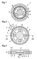
- FIG. 1 an actuator 1 according to a first preferred embodiment of the invention described in detail.
- the actuator 1 comprises a stator 2 with a plurality of poles 2a, on each of which a winding (not shown) is provided.
- a rotor 3 is arranged, which is designed as a hollow rotor. Inside the hollow rotor, an internal toothing 3a is provided.
- a plurality of permanent magnets 4 are arranged along the circumference. In this embodiment, the permanent magnets 4 are fixed by means of gluing on the rotor 3.
- the permanent magnets are made of a rare earth material.
- a planetary gear 5 is arranged inside the hollow rotor.
- the internal gear 3a of the rotor 3 forms the ring gear of the planetary gear 5.
- the planetary gear 5 comprises three planet gears 6 and a sun gear 7.
- the sun gear 7 is arranged centrally in the rotor 3 and arranged stationary on a housing of the actuator. By means of this structure, it is possible in particular to dispense with a separate mounting of the rotor 3.
- the rotor 3 is guided and supported in this embodiment via the three planet gears.
- An output of the planetary gear is provided via a planet carrier, not shown.
- a motor and a transmission of the actuator 1 is a compact unit, wherein the planetary gear 5 is integrated directly in the interior of the hollow rotor.
- the rotor is part of the planetary gear.
- the actuator still has a very simple and inexpensive construction.
- the motor can be used in particular where small speeds and high torque requirements, such as window regulators or sunroof drives, are required.
- the rotor 3 is formed from a stamped laminated core, wherein the laminated core comprises a plurality of stamped individual sheets.
- the laminated core comprises a plurality of stamped individual sheets.
- a deburring step is additionally carried out after the punching process, in particular in the region of the internal toothing, as a result of which a service life of the rotor can be significantly increased.
- the individual sheets are joined together via positive connection elements to the laminated core.
- FIGS. 2 and 3 an actuator 1 according to a second embodiment of the invention described in detail.
- the same or functionally identical parts are denoted by the same reference numerals as in the first embodiment.
- FIGS. 2 and 3 only the rotor is shown schematically together with the integrated planetary gear.
- a stator 2 is, as in the in FIG. 1 shown embodiment, constructed.
- FIG. 2 in contrast to the first embodiment in the second embodiment, the permanent magnets 4 are integrated into the rotor 3 and disposed slightly within the outer periphery of the rotor 3.
- the rotor made of a plurality of sheets on punched recesses for receiving the permanent magnets 4.
- the planetary gear 5 has four planet wheels 6.
- a first sun gear 11 and a second sun gear 12 are provided.
- the two sun gears 11 and 12 are arranged on an axis one behind the other, wherein, however, the first sun gear 11 via a mounting plate 11a with a housing of the actuator (not shown) is connected.
- the second sun gear 12 is connected to an output shaft 10.
- the first sun gear 11 is stationary arranged and the second sun gear 12 is rotatably arranged. In the axial direction, a gap 13 between the first and second sun gear 11, 12 is present.
- a number of teeth of the sun gears is selected such that the second rotatable sun gear 12 has a number of teeth equal to the number of teeth of the first fixed sun gear 11 minus the number of planets 6. That is, when the first sun gear 11 has a number of teeth of 84 and four planetary gears 6 are provided, the rotatable second sun gear 12 has a number of teeth of 80.
- the rotor 3 can be supported via the planet gears 6. Furthermore, the four planet gears 6 can also support the rotatable sun gear 12. Since the stationary first sun gear 11 supports the planet 6, it is not absolutely necessary to provide a planet carrier, but the planet gears 6 can be arranged freely between the internal teeth 3 a and the sun gears 11, 12.
- a support of a differential torque with respect to the housing is taken over the first stationary sun gear 11 during operation.
- an actuator can thus be provided in which a planetary gear is integrated in a hollow rotor shaft of an electric drive.
- a planetary gear is integrated in a hollow rotor shaft of an electric drive.
- the internal toothing of the rotor can also be made of a different material than the laminated core. It is also also possible to store the rotating parts of the drive, such as the rotor and the gears, separately.
Landscapes
- Engineering & Computer Science (AREA)
- Power Engineering (AREA)
- Connection Of Motors, Electrical Generators, Mechanical Devices, And The Like (AREA)
- Retarders (AREA)
Applications Claiming Priority (1)
| Application Number | Priority Date | Filing Date | Title |
|---|---|---|---|
| DE200710060950 DE102007060950A1 (de) | 2007-12-18 | 2007-12-18 | Kompakter Stellantrieb |
Publications (1)
| Publication Number | Publication Date |
|---|---|
| EP2073358A2 true EP2073358A2 (fr) | 2009-06-24 |
Family
ID=40394326
Family Applications (1)
| Application Number | Title | Priority Date | Filing Date |
|---|---|---|---|
| EP20080105625 Withdrawn EP2073358A2 (fr) | 2007-12-18 | 2008-10-21 | Mécanisme de commande compact |
Country Status (3)
| Country | Link |
|---|---|
| EP (1) | EP2073358A2 (fr) |
| CN (1) | CN101465577A (fr) |
| DE (1) | DE102007060950A1 (fr) |
Cited By (5)
| Publication number | Priority date | Publication date | Assignee | Title |
|---|---|---|---|---|
| WO2013189649A1 (fr) * | 2012-06-18 | 2013-12-27 | Robert Bosch Gmbh | Moteur électrique présentant un engrenage planétaire |
| US8834311B1 (en) * | 2013-03-07 | 2014-09-16 | The United States Of America As Represented By The Secretary Of The Army | Concentric electric servomotor/gearbox drive |
| DE102013211301A1 (de) | 2013-06-17 | 2014-12-18 | Robert Bosch Gmbh | Antriebseinrichtung |
| EP2553234A4 (fr) * | 2010-03-31 | 2016-07-06 | Rotrex As | Turbocompresseur à assistance électrique |
| CN110971075A (zh) * | 2018-09-29 | 2020-04-07 | 上海鸣志电器股份有限公司 | 一种一体电机结构 |
Families Citing this family (2)
| Publication number | Priority date | Publication date | Assignee | Title |
|---|---|---|---|---|
| CN101934720B (zh) * | 2009-06-30 | 2014-05-28 | 比亚迪股份有限公司 | 一种混合动力驱动系统及其驱动方法 |
| WO2025232929A1 (fr) * | 2024-05-08 | 2025-11-13 | 上海爱动科技有限公司 | Unité de rotor, structure de transmission planétaire primaire, structure de transmission de type planétaire, mécanisme de réduction de vitesse, moteur à engrenages, roue libre et cycle assisté |
Citations (1)
| Publication number | Priority date | Publication date | Assignee | Title |
|---|---|---|---|---|
| DE10243809A1 (de) | 2002-03-13 | 2004-05-19 | Robert Bosch Gmbh | Stellantrieb |
-
2007
- 2007-12-18 DE DE200710060950 patent/DE102007060950A1/de not_active Withdrawn
-
2008
- 2008-10-21 EP EP20080105625 patent/EP2073358A2/fr not_active Withdrawn
- 2008-12-18 CN CNA2008101859854A patent/CN101465577A/zh active Pending
Patent Citations (1)
| Publication number | Priority date | Publication date | Assignee | Title |
|---|---|---|---|---|
| DE10243809A1 (de) | 2002-03-13 | 2004-05-19 | Robert Bosch Gmbh | Stellantrieb |
Cited By (5)
| Publication number | Priority date | Publication date | Assignee | Title |
|---|---|---|---|---|
| EP2553234A4 (fr) * | 2010-03-31 | 2016-07-06 | Rotrex As | Turbocompresseur à assistance électrique |
| WO2013189649A1 (fr) * | 2012-06-18 | 2013-12-27 | Robert Bosch Gmbh | Moteur électrique présentant un engrenage planétaire |
| US8834311B1 (en) * | 2013-03-07 | 2014-09-16 | The United States Of America As Represented By The Secretary Of The Army | Concentric electric servomotor/gearbox drive |
| DE102013211301A1 (de) | 2013-06-17 | 2014-12-18 | Robert Bosch Gmbh | Antriebseinrichtung |
| CN110971075A (zh) * | 2018-09-29 | 2020-04-07 | 上海鸣志电器股份有限公司 | 一种一体电机结构 |
Also Published As
| Publication number | Publication date |
|---|---|
| CN101465577A (zh) | 2009-06-24 |
| DE102007060950A1 (de) | 2009-06-25 |
Similar Documents
| Publication | Publication Date | Title |
|---|---|---|
| DE102012212268B4 (de) | Antriebssystem für eine Elektrische Achse mit Zwei-Gang-Getriebe | |
| DE102017211881A1 (de) | Antriebseinrichtung zum Antreiben einer elektrischen Achse | |
| DE19841159A1 (de) | Antriebsanordnung für ein Kraftfahrzeug | |
| EP2073358A2 (fr) | Mécanisme de commande compact | |
| WO2014008897A1 (fr) | Concept de montage d'un essieu électrique | |
| DE102017011387A1 (de) | Elektrische Antriebsvorrichtung für ein Kraftfahrzeug | |
| DE102016220630A1 (de) | Antriebseinrichtung zum Antreiben einer elektrischen Achse | |
| EP3493370B1 (fr) | Dispositif d'entraînement ainsi que dispositif d'entraînement d'essieu pour un véhicule automobile | |
| CH702879A2 (de) | Planetengetriebe in Wolfromanordnung sowie Elekromotor mit integriertem Planetengetriebe in Wolfromanordnung. | |
| DE102011114322A1 (de) | Achsdirektantriebsvorrichtung für ein Kraftfahrzeug und Kraftfahrzeug | |
| DE102021208036A1 (de) | Elektrischer Antrieb für ein Fahrzeug | |
| DE102019124666B4 (de) | Differenzialgetriebe | |
| DE102004052562B3 (de) | Kraftfahrzeuglenkung mit Überlagerungsgetriebe | |
| WO2019141561A1 (fr) | Boîte de vitesses pour véhicule automobile, chaîne cinématique de véhicule automobile et procédé permettant de les faire fonctionner | |
| EP2066919B1 (fr) | Démultiplicateur à phase multiple | |
| WO2021074306A1 (fr) | Entraînement électrique pour un véhicule | |
| DE102013211801B4 (de) | Elektromechanischer Aktor | |
| DE102019103242A1 (de) | Elektrische Antriebsvorrichtung für ein Kraftfahrzeug | |
| DE102018101597A1 (de) | Antriebsstrang für ein Transportmittel | |
| WO2014044277A1 (fr) | Système de transmission | |
| WO2021089084A1 (fr) | Transmission hybride et arrangement d'entraînement hybride | |
| DE102020200476A1 (de) | Elektrischer Antrieb für ein Fahrzeug | |
| DE102019207784A1 (de) | Elektrischer Antrieb für ein Fahrzeug in einem Gehäuse | |
| DE102013211812B4 (de) | Umlaufrädergetriebe | |
| WO2013013950A2 (fr) | Motoréducteur |
Legal Events
| Date | Code | Title | Description |
|---|---|---|---|
| PUAI | Public reference made under article 153(3) epc to a published international application that has entered the european phase |
Free format text: ORIGINAL CODE: 0009012 |
|
| AK | Designated contracting states |
Kind code of ref document: A2 Designated state(s): AT BE BG CH CY CZ DE DK EE ES FI FR GB GR HR HU IE IS IT LI LT LU LV MC MT NL NO PL PT RO SE SI SK TR |
|
| AX | Request for extension of the european patent |
Extension state: AL BA MK RS |
|
| STAA | Information on the status of an ep patent application or granted ep patent |
Free format text: STATUS: THE APPLICATION IS DEEMED TO BE WITHDRAWN |
|
| 18D | Application deemed to be withdrawn |
Effective date: 20130503 |