EP2073601A2 - Elektrischer Strahlungsheizer - Google Patents
Elektrischer Strahlungsheizer Download PDFInfo
- Publication number
- EP2073601A2 EP2073601A2 EP20080382072 EP08382072A EP2073601A2 EP 2073601 A2 EP2073601 A2 EP 2073601A2 EP 20080382072 EP20080382072 EP 20080382072 EP 08382072 A EP08382072 A EP 08382072A EP 2073601 A2 EP2073601 A2 EP 2073601A2
- Authority
- EP
- European Patent Office
- Prior art keywords
- insulating base
- face
- radiant heater
- electric radiant
- area
- Prior art date
- Legal status (The legal status is an assumption and is not a legal conclusion. Google has not performed a legal analysis and makes no representation as to the accuracy of the status listed.)
- Granted
Links
- 238000010411 cooking Methods 0.000 claims abstract description 6
- 239000002184 metal Substances 0.000 claims abstract description 5
- 239000002241 glass-ceramic Substances 0.000 claims abstract description 4
- 238000010438 heat treatment Methods 0.000 claims abstract description 4
- 238000000034 method Methods 0.000 claims description 2
- 239000000463 material Substances 0.000 description 4
- 239000004965 Silica aerogel Substances 0.000 description 3
- VYPSYNLAJGMNEJ-UHFFFAOYSA-N Silicium dioxide Chemical compound O=[Si]=O VYPSYNLAJGMNEJ-UHFFFAOYSA-N 0.000 description 3
- 239000000919 ceramic Substances 0.000 description 3
- 239000011810 insulating material Substances 0.000 description 3
- 238000010521 absorption reaction Methods 0.000 description 2
- PNEYBMLMFCGWSK-UHFFFAOYSA-N aluminium oxide Inorganic materials [O-2].[O-2].[O-2].[Al+3].[Al+3] PNEYBMLMFCGWSK-UHFFFAOYSA-N 0.000 description 2
- 239000000428 dust Substances 0.000 description 2
- 238000009413 insulation Methods 0.000 description 2
- 239000012229 microporous material Substances 0.000 description 2
- 238000000465 moulding Methods 0.000 description 2
- 239000002356 single layer Substances 0.000 description 2
- 230000006835 compression Effects 0.000 description 1
- 238000007906 compression Methods 0.000 description 1
- 229910052878 cordierite Inorganic materials 0.000 description 1
- JSKIRARMQDRGJZ-UHFFFAOYSA-N dimagnesium dioxido-bis[(1-oxido-3-oxo-2,4,6,8,9-pentaoxa-1,3-disila-5,7-dialuminabicyclo[3.3.1]nonan-7-yl)oxy]silane Chemical compound [Mg++].[Mg++].[O-][Si]([O-])(O[Al]1O[Al]2O[Si](=O)O[Si]([O-])(O1)O2)O[Al]1O[Al]2O[Si](=O)O[Si]([O-])(O1)O2 JSKIRARMQDRGJZ-UHFFFAOYSA-N 0.000 description 1
- 239000010410 layer Substances 0.000 description 1
- 238000004519 manufacturing process Methods 0.000 description 1
- 239000011159 matrix material Substances 0.000 description 1
- 239000003605 opacifier Substances 0.000 description 1
- 230000003252 repetitive effect Effects 0.000 description 1
- -1 steatite Inorganic materials 0.000 description 1
- 239000002470 thermal conductor Substances 0.000 description 1
Images


Classifications
-
- H—ELECTRICITY
- H05—ELECTRIC TECHNIQUES NOT OTHERWISE PROVIDED FOR
- H05B—ELECTRIC HEATING; ELECTRIC LIGHT SOURCES NOT OTHERWISE PROVIDED FOR; CIRCUIT ARRANGEMENTS FOR ELECTRIC LIGHT SOURCES, IN GENERAL
- H05B3/00—Ohmic-resistance heating
- H05B3/68—Heating arrangements specially adapted for cooking plates or analogous hot-plates
- H05B3/74—Non-metallic plates, e.g. vitroceramic, ceramic or glassceramic hobs, also including power or control circuits
- H05B3/748—Resistive heating elements, i.e. heating elements exposed to the air, e.g. coil wire heater
Definitions
- This invention relates to an electric radiant heater adapted to a cooking hob, in particular a glass-ceramic cooktop.
- Electric radiant heaters adapted to a cooking hob are know in the prior art, and which comprise a metal support cover that houses in its interior an insulating base that includes a perimeter rim and upon which is fixed at least one thermal conductor, said support cover including a support projection that projects out in relation to its base, as disclosed in documents ES 1054629U and EP 1139696A .
- the insulating base is made of a thermal insulating material obtained by compression, which comprises a micro-porous silica aerogel reinforced with ceramic fibres and, optionally, alumina and an opacifier, with the result that said insulating base has good mechanical and thermal insulation properties, as disclosed in document GB 1580909 A .
- the insulating base In general terms, the insulating base, the faces of which are substantially flat, is supported on the support projection of the support cover via the perimeter rim, whereas in the bottom surface, generally convex, of the support cover, there is a non-uniform gap between the insulating base and the bottom of said support cover.
- the object of this invention is to provide an electric radiant heater adapted to a cooking hob, in particular a glass-ceramic cooktop, as defined in the claims.
- the electric radiant heater of the invention comprises an insulating base that has, on one end, a substantially flat and circular first face upon which at least one heating resistance is fixed, and, on the opposite end, a substantially circular second face, and a metal support cover that houses said insulating base in its interior.
- the second face of the insulating base is supported directly on the bottom surface of the support cover via a contact surface, the area of said contact surface being smaller than the area of the circle delimited by the second face of said insulating base.
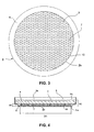
- an electric radiant heater adapted to a cooking hob, not shown in the figures, comprises a substantially revolving insulating base 2 that has, on one end, a substantially flat and circular first face 2a upon which are fixed one or more heating resistances, not shown in the figures, and on the opposite end, a substantially flat and circular second face 2b defined by a diameter D1, and a metal support cover 3 adapted to the external shape of the insulating base 2, which houses said insulating base 2 in its interior.
- the support cover 3 has a substantially vertical wall 3b of a height greater than a thickness H2 of the insulating base 2, and a bottom surface 3a upon which the second face 2b of the insulating base 2 is supported directly via a contact surface 10, the area of said contact surface 10 being smaller than the area of the circle of diameter D1 delimited by the second face 2b.
- the insulating base 2 is formed by moulding a single layer of uniform micro-porous material, a good heat-insulating material with good mechanical properties and resistant to the absorption of moisture, which comprises a silica aerogel dust mixed with ceramic-reinforcing fibres, and, optionally, opacifying materials and ceramic loads.
- the insulating base 2 includes a plurality of holes 6, symmetrically disposed on the second face 2b, which reduce the area of the contact surface 10 of said second face 2b with the bottom surface 3a, and create layers of insulating air between the insulating base 2 and the support cover 3.
- the holes 6 are blind holes defined by a height H1, which is smaller than the thickness H2 of the insulating base 2.
- the insulating base 2 comprises a first substantially cylindrical element 4, one of the two faces of which corresponds to the first face 2a of the insulating base 2, and a second substantially cylindrical element 5, one of the two faces of which corresponds to the second face 2b of the insulating base 2, said first element 4 and second element 5 being coaxial and said first element 4 being supported on the second element 5.
- the first element 4 is formed by moulding a single layer of uniform micro-porous material, a good heat-insulating material with good mechanical properties and resistant to the absorption of moisture, which comprises a silica aerogel dust mixed with ceramic-reinforcing fibres and, optionally, opacifying materials and ceramic loads, while the second element 5 is made of a material with good mechanical properties, such as alumina, steatite, cordierite or a similar material.
- the second element 5 includes a plurality of corresponding holes 7, symmetrically disposed in a beehive panel arrangement, said holes 7 being through-holes, and which reduce the area of the contact surface 10 of the insulating base 2 with the support cover 3, and create air cavities that improve the insulation between the insulating base 2 and the support cover 3.
- the support cover 3 includes projections 8 towards the interior of the support cover 3, made by means of a stamping procedure, and upon which the second face 2b of the insulating base 2 is supported, thereby reducing the contact surface 10 between the insulating base 2 and the support cover 3.
- the projections 8 may have varying shapes, being capable of taking the form of a matrix of individual projections, of rectilinear channels or concentric circular channels.
Landscapes
- Chemical & Material Sciences (AREA)
- Engineering & Computer Science (AREA)
- Ceramic Engineering (AREA)
- Resistance Heating (AREA)
- Electric Stoves And Ranges (AREA)
Applications Claiming Priority (1)
| Application Number | Priority Date | Filing Date | Title |
|---|---|---|---|
| ES200702652U ES1066972Y (es) | 2007-12-21 | 2007-12-21 | Foco radiante electrico |
Publications (3)
| Publication Number | Publication Date |
|---|---|
| EP2073601A2 true EP2073601A2 (de) | 2009-06-24 |
| EP2073601A3 EP2073601A3 (de) | 2009-08-26 |
| EP2073601B1 EP2073601B1 (de) | 2015-03-25 |
Family
ID=39168027
Family Applications (1)
| Application Number | Title | Priority Date | Filing Date |
|---|---|---|---|
| EP20080382072 Not-in-force EP2073601B1 (de) | 2007-12-21 | 2008-12-04 | Elektrischer Strahlungsheizer |
Country Status (2)
| Country | Link |
|---|---|
| EP (1) | EP2073601B1 (de) |
| ES (2) | ES1066972Y (de) |
Citations (4)
| Publication number | Priority date | Publication date | Assignee | Title |
|---|---|---|---|---|
| GB1580909A (en) | 1977-02-10 | 1980-12-10 | Micropore Internatioonal Ltd | Thermal insulation material |
| DE19919784A1 (de) | 1999-04-30 | 2000-11-02 | Diehl Ako Stiftung Gmbh & Co | Aufnahmeschale mit einer Isolierschicht für Strahlungsheizelemente und Verfahren zur Herstellung von Kanälen in der Isolierschicht |
| EP1139696A2 (de) | 2000-03-23 | 2001-10-04 | Ceramaspeed Limited | Elektrischer Wärmestrahler |
| ES1054629U (es) | 2003-04-25 | 2003-08-16 | Eika S Coop | "foco radiante para una placa de cocina con un aro aislante" |
Family Cites Families (3)
| Publication number | Priority date | Publication date | Assignee | Title |
|---|---|---|---|---|
| DE2205132C3 (de) * | 1972-02-03 | 1980-09-04 | E.G.O. Elektro-Geraete Blanc U. Fischer, 7519 Oberderdingen | Elektrokochgerät |
| DE3034495A1 (de) * | 1980-09-12 | 1982-03-25 | Grünzweig + Hartmann und Glasfaser AG, 6700 Ludwigshafen | Vorrichtung zur waermedaemmung einer waermequelle |
| DE3810586A1 (de) * | 1988-03-29 | 1989-10-12 | Ego Elektro Blanc & Fischer | Beheizung fuer elektrische kochgeraete |
-
2007
- 2007-12-21 ES ES200702652U patent/ES1066972Y/es not_active Expired - Lifetime
-
2008
- 2008-12-04 EP EP20080382072 patent/EP2073601B1/de not_active Not-in-force
- 2008-12-04 ES ES08382072.0T patent/ES2533905T3/es active Active
Patent Citations (4)
| Publication number | Priority date | Publication date | Assignee | Title |
|---|---|---|---|---|
| GB1580909A (en) | 1977-02-10 | 1980-12-10 | Micropore Internatioonal Ltd | Thermal insulation material |
| DE19919784A1 (de) | 1999-04-30 | 2000-11-02 | Diehl Ako Stiftung Gmbh & Co | Aufnahmeschale mit einer Isolierschicht für Strahlungsheizelemente und Verfahren zur Herstellung von Kanälen in der Isolierschicht |
| EP1139696A2 (de) | 2000-03-23 | 2001-10-04 | Ceramaspeed Limited | Elektrischer Wärmestrahler |
| ES1054629U (es) | 2003-04-25 | 2003-08-16 | Eika S Coop | "foco radiante para una placa de cocina con un aro aislante" |
Also Published As
| Publication number | Publication date |
|---|---|
| ES1066972Y (es) | 2008-07-01 |
| EP2073601B1 (de) | 2015-03-25 |
| EP2073601A3 (de) | 2009-08-26 |
| ES1066972U (es) | 2008-04-01 |
| ES2533905T3 (es) | 2015-04-15 |
Similar Documents
| Publication | Publication Date | Title |
|---|---|---|
| KR101375570B1 (ko) | 복사전열 히터 | |
| DE2551137C2 (de) | Elektrischer Strahlungsheizkörper für Glaskeramikkochplatten | |
| DE19746845C1 (de) | Anordnung eines keramischen Heizelementes als Kochzone in einer Aussparung einer Fläche | |
| DE19527826C2 (de) | Strahlungs-Kochstelleneinheit | |
| JP5411060B2 (ja) | 真空断熱構造体、真空断熱加熱ヒータおよび真空断熱加熱ヒータを用いた加熱装置 | |
| DE69830980T2 (de) | Zirkuläres Schichtsheizelement und Kochherd aus Porzellan-Email | |
| CA2943281A1 (en) | High performance surface unit for heating | |
| EP2073601B1 (de) | Elektrischer Strahlungsheizer | |
| EP0980193A1 (de) | Beheizbares Flächenelement | |
| EP0757508B1 (de) | Kochmuldeneinheit mit mehreren unterhalb einer Platte angeordneten Kochstellen | |
| US20010035405A1 (en) | Modular radiant heating unit having a thermally insulating gasket and methods of assembling same | |
| DE19527824A1 (de) | Kochmuldeneinheit mit mehreren unterhalb einer Platte angeordneten Kochstellen | |
| BE1029280B1 (de) | Küchenutensil zum Aufstellen auf ein Induktionskochfeld | |
| EP2631545B1 (de) | Heizplatte mit mindestens einem Temperatursensorelement | |
| CN117528848B (zh) | 一种陶瓷基红外加热装置及其加工方法 | |
| CN104513886B (zh) | 一种低温退火井式电阻炉的炉体及其安装工艺 | |
| US20060027562A1 (en) | Radiant heater for a cooker, with a moulded insulating base | |
| CA2635142A1 (en) | Heating device | |
| CN222765079U (zh) | 烤箱 | |
| CN222884809U (zh) | 加热组件和烹饪设备 | |
| JPH0414879Y2 (de) | ||
| CN210051166U (zh) | 一种隧道窑用推板 | |
| DE10001330A1 (de) | Elektrokochplatte | |
| KR102431951B1 (ko) | 단열재의 복사 차단 방법 및 이를 이용하여 제조되는 단열재 | |
| KR200316602Y1 (ko) | 전기온돌판 |
Legal Events
| Date | Code | Title | Description |
|---|---|---|---|
| PUAI | Public reference made under article 153(3) epc to a published international application that has entered the european phase |
Free format text: ORIGINAL CODE: 0009012 |
|
| AK | Designated contracting states |
Kind code of ref document: A2 Designated state(s): AT BE BG CH CY CZ DE DK EE ES FI FR GB GR HR HU IE IS IT LI LT LU LV MC MT NL NO PL PT RO SE SI SK TR |
|
| AX | Request for extension of the european patent |
Extension state: AL BA MK RS |
|
| PUAL | Search report despatched |
Free format text: ORIGINAL CODE: 0009013 |
|
| AK | Designated contracting states |
Kind code of ref document: A3 Designated state(s): AT BE BG CH CY CZ DE DK EE ES FI FR GB GR HR HU IE IS IT LI LT LU LV MC MT NL NO PL PT RO SE SI SK TR |
|
| AX | Request for extension of the european patent |
Extension state: AL BA MK RS |
|
| 17P | Request for examination filed |
Effective date: 20091218 |
|
| 17Q | First examination report despatched |
Effective date: 20100121 |
|
| AKX | Designation fees paid |
Designated state(s): DE ES FR IT |
|
| GRAP | Despatch of communication of intention to grant a patent |
Free format text: ORIGINAL CODE: EPIDOSNIGR1 |
|
| GRAS | Grant fee paid |
Free format text: ORIGINAL CODE: EPIDOSNIGR3 |
|
| GRAA | (expected) grant |
Free format text: ORIGINAL CODE: 0009210 |
|
| INTG | Intention to grant announced |
Effective date: 20150209 |
|
| AK | Designated contracting states |
Kind code of ref document: B1 Designated state(s): DE ES FR IT |
|
| REG | Reference to a national code |
Ref country code: ES Ref legal event code: FG2A Ref document number: 2533905 Country of ref document: ES Kind code of ref document: T3 Effective date: 20150415 |
|
| REG | Reference to a national code |
Ref country code: DE Ref legal event code: R096 Ref document number: 602008037300 Country of ref document: DE Effective date: 20150507 |
|
| REG | Reference to a national code |
Ref country code: DE Ref legal event code: R097 Ref document number: 602008037300 Country of ref document: DE |
|
| PLBE | No opposition filed within time limit |
Free format text: ORIGINAL CODE: 0009261 |
|
| STAA | Information on the status of an ep patent application or granted ep patent |
Free format text: STATUS: NO OPPOSITION FILED WITHIN TIME LIMIT |
|
| 26N | No opposition filed |
Effective date: 20160105 |
|
| REG | Reference to a national code |
Ref country code: FR Ref legal event code: ST Effective date: 20160831 |
|
| PG25 | Lapsed in a contracting state [announced via postgrant information from national office to epo] |
Ref country code: FR Free format text: LAPSE BECAUSE OF NON-PAYMENT OF DUE FEES Effective date: 20151231 |
|
| PG25 | Lapsed in a contracting state [announced via postgrant information from national office to epo] |
Ref country code: IT Free format text: LAPSE BECAUSE OF NON-PAYMENT OF DUE FEES Effective date: 20151204 |
|
| PGFP | Annual fee paid to national office [announced via postgrant information from national office to epo] |
Ref country code: DE Payment date: 20211227 Year of fee payment: 14 |
|
| PGFP | Annual fee paid to national office [announced via postgrant information from national office to epo] |
Ref country code: ES Payment date: 20220105 Year of fee payment: 14 |
|
| REG | Reference to a national code |
Ref country code: DE Ref legal event code: R119 Ref document number: 602008037300 Country of ref document: DE |
|
| PG25 | Lapsed in a contracting state [announced via postgrant information from national office to epo] |
Ref country code: DE Free format text: LAPSE BECAUSE OF NON-PAYMENT OF DUE FEES Effective date: 20230701 |
|
| REG | Reference to a national code |
Ref country code: ES Ref legal event code: FD2A Effective date: 20240126 |
|
| PG25 | Lapsed in a contracting state [announced via postgrant information from national office to epo] |
Ref country code: ES Free format text: LAPSE BECAUSE OF NON-PAYMENT OF DUE FEES Effective date: 20221205 |
|
| PG25 | Lapsed in a contracting state [announced via postgrant information from national office to epo] |
Ref country code: ES Free format text: LAPSE BECAUSE OF NON-PAYMENT OF DUE FEES Effective date: 20221205 |