EP2074330B1 - Mehrstufige pumpenanordnung - Google Patents
Mehrstufige pumpenanordnung Download PDFInfo
- Publication number
- EP2074330B1 EP2074330B1 EP07818852.1A EP07818852A EP2074330B1 EP 2074330 B1 EP2074330 B1 EP 2074330B1 EP 07818852 A EP07818852 A EP 07818852A EP 2074330 B1 EP2074330 B1 EP 2074330B1
- Authority
- EP
- European Patent Office
- Prior art keywords
- pump
- volute
- modular
- different
- flange
- Prior art date
- Legal status (The legal status is an assumption and is not a legal conclusion. Google has not performed a legal analysis and makes no representation as to the accuracy of the status listed.)
- Not-in-force
Links
Images


Classifications
-
- F—MECHANICAL ENGINEERING; LIGHTING; HEATING; WEAPONS; BLASTING
- F04—POSITIVE - DISPLACEMENT MACHINES FOR LIQUIDS; PUMPS FOR LIQUIDS OR ELASTIC FLUIDS
- F04D—NON-POSITIVE-DISPLACEMENT PUMPS
- F04D29/00—Details, component parts, or accessories
- F04D29/40—Casings; Connections of working fluid
- F04D29/42—Casings; Connections of working fluid for radial or helico-centrifugal pumps
- F04D29/426—Casings; Connections of working fluid for radial or helico-centrifugal pumps especially adapted for liquid pumps
-
- F—MECHANICAL ENGINEERING; LIGHTING; HEATING; WEAPONS; BLASTING
- F04—POSITIVE - DISPLACEMENT MACHINES FOR LIQUIDS; PUMPS FOR LIQUIDS OR ELASTIC FLUIDS
- F04D—NON-POSITIVE-DISPLACEMENT PUMPS
- F04D1/00—Radial-flow pumps, e.g. centrifugal pumps; Helico-centrifugal pumps
- F04D1/06—Multi-stage pumps
- F04D1/063—Multi-stage pumps of the vertically split casing type
-
- F—MECHANICAL ENGINEERING; LIGHTING; HEATING; WEAPONS; BLASTING
- F04—POSITIVE - DISPLACEMENT MACHINES FOR LIQUIDS; PUMPS FOR LIQUIDS OR ELASTIC FLUIDS
- F04D—NON-POSITIVE-DISPLACEMENT PUMPS
- F04D29/00—Details, component parts, or accessories
- F04D29/40—Casings; Connections of working fluid
- F04D29/42—Casings; Connections of working fluid for radial or helico-centrifugal pumps
- F04D29/426—Casings; Connections of working fluid for radial or helico-centrifugal pumps especially adapted for liquid pumps
- F04D29/4293—Details of fluid inlet or outlet
-
- F—MECHANICAL ENGINEERING; LIGHTING; HEATING; WEAPONS; BLASTING
- F04—POSITIVE - DISPLACEMENT MACHINES FOR LIQUIDS; PUMPS FOR LIQUIDS OR ELASTIC FLUIDS
- F04D—NON-POSITIVE-DISPLACEMENT PUMPS
- F04D29/00—Details, component parts, or accessories
- F04D29/60—Mounting; Assembling; Disassembling
- F04D29/605—Mounting; Assembling; Disassembling specially adapted for liquid pumps
-
- F—MECHANICAL ENGINEERING; LIGHTING; HEATING; WEAPONS; BLASTING
- F04—POSITIVE - DISPLACEMENT MACHINES FOR LIQUIDS; PUMPS FOR LIQUIDS OR ELASTIC FLUIDS
- F04D—NON-POSITIVE-DISPLACEMENT PUMPS
- F04D29/00—Details, component parts, or accessories
- F04D29/60—Mounting; Assembling; Disassembling
- F04D29/62—Mounting; Assembling; Disassembling of radial or helico-centrifugal pumps
- F04D29/628—Mounting; Assembling; Disassembling of radial or helico-centrifugal pumps especially adapted for liquid pumps
-
- Y—GENERAL TAGGING OF NEW TECHNOLOGICAL DEVELOPMENTS; GENERAL TAGGING OF CROSS-SECTIONAL TECHNOLOGIES SPANNING OVER SEVERAL SECTIONS OF THE IPC; TECHNICAL SUBJECTS COVERED BY FORMER USPC CROSS-REFERENCE ART COLLECTIONS [XRACs] AND DIGESTS
- Y10—TECHNICAL SUBJECTS COVERED BY FORMER USPC
- Y10T—TECHNICAL SUBJECTS COVERED BY FORMER US CLASSIFICATION
- Y10T29/00—Metal working
- Y10T29/53—Means to assemble or disassemble
Definitions
- This invention relates generally to pump assemblies, and more particularly, to multistage end-suction pump assemblies.
- Pump assemblies are provided within pipe systems of residential, commercial or industrial facilities for increasing the pressure and flow of the fluid within the pipe system.
- the pump assembly is usually fitted to the pipe system to circulate the fluid under pressure.
- the typical pump assembly has an inlet that supplies fluid to the pump through a manifold having an impeller chamber, an impeller located in the chamber, a power head (e.g. motor and shaft) to drive the impeller, and an outlet that returns the fluid to the pipe system.
- the inlet is fitted to a supply pipe and the outlet is fitted to a discharge pipe.
- the size of the pump assembly is selected based on the particular pipe system and the desired pressure and flow of the fluid within the pipe system. For example, various pump assembly components may be provided to accommodate various sized supply pipes and discharge pipes, which are typically different than one another.
- the particular pump assembly components chosen depend on the particular application. In another example, in applications where a high pressure is desired, a pump assembly having a relatively larger motor or a relatively larger impeller may be used. In some known pump assemblies, multiple impellers are used, such as in a multistage pump assembly.
- the multistage pump assemblies typically have one of two configurations, namely a horizontal configuration and a vertical configuration. In both configurations, the pump assemblies typically stack the multiple impellers in stages in series. In the horizontal configuration, the stack is oriented generally horizontally when installed; and in the vertical configuration, the stack is oriented generally vertically when installed.
- volute or manifold is provided at one end of the pump stack and including inlet and outlet of the pump.
- the drive motor is connected with the pump stack.
- size and type of the pump stack may vary depending on the use of pump, it necessary to provide different manifolds or volutes which are designed to be connected to a certain pump stack, for example depending on the diameter of the pump stack.
- the design of the manifold or volute depends on the required design of inlet and outlet so that the inlet and outlet can be connected with an existing pipe system.
- inlet and outlet may be arranged in line or angled, for example by 90° to one another.
- the diameter of inlet and outlet and also the length of inlet and outlet may be designed depending on the pipe system into which the pump has to be integrated. Therefore, many different types of manifolds or volutes are required for the different types of pump stacks and different installations for the pump assembly.
- US 5,201,633 discloses a multistage pump assembly having a volute connected to a stack of pump stages.
- the object of the invention to provide an improved system for assembling a modular multistage pump assembly which allows a universal use for different pipe systems and with different sized pump stacks and avoids to provide many different types of manifolds or volutes to connect the pump stack with the pipe system.
- a system for assembling a modular multistage pump assembly including a volute having a suction side and a pressure side, a pump stack having at least one stage, and a modular flange coupled to each of the volute and the pump stack.
- the volute or manifold comprises a suction chamber and a pressure chamber and is connected with the pump stack having at least one stage, but preferably comprising more than one stage.
- the volute and the pump stack are not directly coupled with each other, but by a modular flange arranged between the volute and the pump stack.
- the modular flange is removably coupled to both the pump stack and the volute.
- the modular flange is a connection element providing the connection of the volute and the pump stack.
- the modular flange may serve as an adapter to connect different pump stacks with the same volute or different volutes with the same pump stack.
- the modular flange By use of the modular flange it is not necessary to specially adapt the volute to a certain pump stack design or to design the pump stack corresponding to the design of a certain volute. It is sufficient to just provide several modular flanges of different design which can be used to couple the different volutes or pump stacks with each other. By this the number of different volutes necessary to couple different pump stacks with different pipe systems can be reduced since the necessary number of volutes depends only on the design of the pipe system to which the pump shall be coupled. For connecting the volute with different types or sizes of pump stacks the adapter in form of the modular flange is used. It is much easier to provide different modular flanges than different volutes so that the costs for the different pump designs can be reduced. This will give the benefit of less inventory and increased on-time delivery to the customer.
- the modular flange is exchangeable in such a way that different volutes and pump stacks may be connected with one another by use of a corresponding modular flange.
- different adapters for connecting volute and pump stack are provided.
- the modular flange has two surfaces opposite to one another, wherein the first surface is designed corresponding to a connection surface of the volute or manifold and the second surface is designed corresponding to a connection surface of the pump stack.
- the first surface of the modular flange is adapted to the design of the interface of the volute for connection with the pump stack.
- the opposite surface of the modular flange is designed corresponding to the interconnection elements or surface of the pump stack.
- the pump stack and/or the volute comprise at least a first and a second type and the modular flange is configured to be coupled to each of the first type and the second type.
- the modular flange may have two sets of connection elements such as screw holes for connecting the modular flange with two different types of pump stacks or with two different types of volutes.
- the pump stack and/or the volute comprise at least a first and a second size and that the modular flange is configured to be coupled to each of the first size and the second size.
- the same modular flange may be coupled for example with two different sized pump stacks or with two different sized volutes.
- the modular flange defines a suction chamber and a pressure chamber.
- the suction chamber of the modular flange is connected with the suction chamber of the volute and the pressure chamber of the modular flange is in connection with the pressure chamber of the volute.
- the suction chamber of the volute can be connected with the suction channel of the pump stack by the suction chamber of the modular flange.
- the pressure chamber of the volute can be connected with the pressure channel of the pump stack by the pressure chamber in the modular flange.
- the modular flange connecting the pump stack and the volute includes concentric rings defining a radial inner channel in direct fluid communication with the suction chamber of the volute and an a radial outer channel in direct fluid communication with a pressure chamber of the volute.
- the radial inner channel is the suction chamber of the modular flange and the radial outer channel is the pressure chamber of the modular flange.
- the inner channel and the outer channel may be separated from one another by a cylindrical wall which is connected with the radial outer part of the modular flange by one or more ribs, preferably extending in radial direction.
- the pump stack includes at least two stages of diffusers abutting one another and defining an axially extending inner tube and axially extending sleeve being radially spaced outwards with respect to the inner tube, wherein the inner tube defining a suction channel along the inner portion of the tube and the inner tube and the sleeve defining a pressure channel there between, the suction channel being in fluid communication with the inner channel of the modular flange and the pressure channel being in fluid communication with the outer channel of the modular flange.
- the modular flange has a ring shaped or cylindrical wall having substantially the same diameter as the inner tube of the pump stack, so that the axial end of the inner tube of the pump stack and the cylindrical wall of the modular flange may come in contact with one another so that a suction channel extending through the inner part of the modular flange and the inner part of the pump stack is formed.
- a ring shaped outer pressure channel surrounding the inner tube of the pump stack and cylindrical wall of the modular flange is formed.
- the modular flange comprises at least one set of fastening elements for coupling with the pump stack and at least one set of fastening elements for coupling with the volute.
- the fastening elements of the modular flange are arranged an designed so that they can be connected with corresponding fastening elements of at least one volute and at least one pump stack.
- the fastening elements for coupling with the pump stack and/or the fastening elements for coupling with the volutes comprise a set of holes in the modular flange. These holes can be used to introduce screws or bolts for connecting the modular flange with the volute and/or with the pump stack.
- At least one seal is provided between the modular flange and the volute and/or between the modular flange and the pump stack. Such seals are used to form fluid channels extending from the volute through the modular flange to the pump stack which are fluid tight to one another and to the outside.
- the volute comprises an inlet connected to the suction chamber and an outlet connected to the pressure chamber of the volute.
- the inlet and the outlet are used for connection with a pipe system.
- the volute comprises an inlet fitting and/or an outlet fitting removably coupled to the inlet and outlet, respectively.
- These fitting may be used to connect the same volute with different pipe systems.
- the fittings may have different lengths so that the pump assembly can easily be introduced in an existing pipe system in which the pipe ends for connecting with the pump assembly are already located at predefined positions.
- the fittings serve as adapters for connecting one volute with different pipe systems.
- it may be possible to provide fittings having different sized connection ends for connecting with the surrounding pipe system so that it is possible to easily connect the volute with different sized pipes.
- the inlet fitting and/or the outlet fitting is exchangeable in such a way that fittings of different size and/or type can be coupled with the volute to enable the integration of the pump assembly into different pipe systems.
- the invention refers to a system for assembling a modular pump assembly according to the preceding description.
- This system comprises at least two different pump stacks and/or at least two different volutes and at least two different modular flanges. These at least two modular flanges are configured such that they allow the coupling of the different pump stacks with the different volutes. It is preferred to provide so many different modular flanges, that each desired combination of a pump stack and a volute can be achieved by using a special modular flange for connecting both.
- a multistage end-suction pump assembly including a pump stack extending between a volute end and a head end, wherein the pump stack includes at least one stage of impellers aligned to rotate about a rotation axis.
- the pump assembly also includes a volute coupled to the volute end of the pump stack, wherein the volute includes an inlet and an outlet being oriented non-parallel with respect to one another.
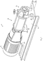
- FIG. 1 is a side perspective view of a pump assembly 10 formed in accordance with an exemplary embodiment.
- the pump assembly 10 includes a pump motor 12, a multistage pump stack 14 and a manifold or volute 16.
- the pump assembly 10 may be installed in an existing or new pipe system to a supply pipe and a discharge pipe (not shown) for increasing the pressure and/or flow of water or another fluid within the pipe system.
- the pump assembly 10 represents a horizontal pump assembly that may be mounted to a base 18 via a plurality of supports or braces, such as motor supports 20, a pump stack support 22, and volute supports 24.
- the base 18 is generally planar and is oriented horizontally, and may be mounted, directly or indirectly to a ground or building surface (not shown). While various embodiments of horizontal pump assemblies are described below, it is understood that the pump assembly 10 may be beneficial in other, non-horizontal applications as well. The following embodiments are therefore provided for illustrative purposes only.
- FIG. 2 is an exploded view of the pump assembly 10, illustrating the motor 12, the pump stack 14 and the volute 16 being axially aligned with one another along a longitudinal or rotation axis 30.
- the motor 12 includes a motor shaft 32 aligned with the rotation axis 30, and the pump stack 14 includes a pump shaft 34 aligned with the rotation axis 30.
- the motor shaft 32 and the pump shaft 34 are interconnected by a shaft coupling 36 for transferring rotational movement from the motor shaft 32 to the pump shaft 34.
- the shaft coupling 36 is housed within an enclosure 38 extending between the motor 12 and the pump stack 14.
- the pump stack 14 includes a pump head 40 and a sleeve 42 extending from the pump head 40 to a sleeve flange 44 opposite the pump head 40.
- the sleeve 42 has a generally circular cross section and defines a chamber through which the fluid flows.
- the pump stack 14 includes an inner channel or chamber and an outer channel or chamber through which the fluid is channeled.
- the sleeve 42 defines a radially outer surface of the outer chamber.
- the sleeve flange 44 is separately provided from, and coupled to, the sleeve 42.
- the sleeve flange 44 is retained in place with respect to the sleeve 42 and the pump head 40 by multiple staybolts 46 extending between the pump head 40 and the sleeve flange 44.
- the pump shaft 34 extends through the pump stack 14 and is substantially centered within the chamber defined by the sleeve 42.
- an end of the pump shaft 34 may be supported by a bearing support 48 integrated with the sleeve flange 44.
- the sleeve flange 44 forms a modular flange serving as an adapter for coupling different pump stacks and volutes with one another.
- the sleeve flange 44 on one side is designed or configured to be connected with the pump stack in particular with the sleeve 42, the impeller assemblies 86 (see fig. 3 ) and the staybolts 46.
- the sleeve flange 44 is configured to be coupled with the rear end 52 of the volute 16. In case that a different sized or different configured pump stack 14 should be connected with the same volute 16, just a different sleeve flange 44 can be used to couple the pump stack 14 with the same volute 16.
- This different sleeve flange 44 has a different design for connection with the different pump stack 14 but on the other side the same configuration or design for connecting with the rear end 52 of the volute 16.
- the volute 16 includes a front end 50, a rear end 52, a top 54, a bottom 56, and sides 58 and 60.
- the volute supports 24 may be coupled to the sides 58, 60 using known fasteners or known fastening methods.
- the volute 16 is coupled to the sleeve flange 44 via a volute flange 62 extending radially outward at the rear end 52 of the volute 16, such as using known fasteners and known fastening methods.
- the volute 16 is coupled to the sleeve flange 44 such that the volute 16 is in fluid communication with the pump stack 14.
- the volute 16 represents an end-suction volute having an inlet 64 at the front end 50 and an outlet 66 at the top 54.
- the inlet 64 and the outlet 66 are non-parallel with respect to one another, such that the volute 16 has a non-in-line configuration (e.g. an orientation in which the inlet and the outlet are not aligned with one another along an axis).
- the inlet 64 and the outlet 66 may be generally perpendicular with respect to one another, such as the end-suction, 90 degree discharge configuration illustrated in Figure 2 .
- the inlet 64 is oriented in-line with the rotation axis 30 such that the fluid flows through the inlet 64, the volute 16, the sleeve flange 44 and the pump stack 14 in a direction along the rotation axis 30, shown by the arrow A.
- Other configurations and orientations of the inlet and outlet 64 and 66 are contemplated in alternative embodiments, such as on the front end 50, top 54, bottom 56 or sides 58, 60 in a non-in-line configuration.
- the volute 16 includes an inlet fitting 68 and an outlet fitting 70 coupled to the inlet 64 and outlet 66, respectively.
- the fittings 68, 70 are separately provided from the volute 16 and mountable thereto.
- the fittings 68, 70 can be used as adapters to connect the volute 16 with pipe systems of different configuration and size.
- the fittings 68, 70 may be securely coupled to the volute 16 using known fasteners or fastening methods.
- the fittings 68, 70 may be threadably coupled to the volute 16; the fittings 68, 70 may be coupled to the volute 16 using a integral flanges and corresponding fasteners; the fittings 68, 70 may be soldered or welded to the volute 16; and the like.
- the fittings 68, 70 are also configured for attachment to the supply and discharge pipes, respectively, such as by a flange coupling, a threaded coupling, a soldered coupling, and the like.
- the type and size of fitting 68, 70 (e.g. flange, threaded, and the like) may be selected based on the type of mating fitting included on the supply and discharge pipes.
- a modular volute 16 is thus provided that may be adapted for installation to an existing piping system.
- the types of fittings 68, 70 may be the same and/or the size of the opening of the fittings 68, 70 may be the same.
- the type and/or size of the fittings 68, 70 may be different than one another.
- the outlet fitting 70 constitutes a modular discharge spool having first and second flanges at the ends thereof. Multiple discharge spools may be provided with the pump assembly 10, wherein each spool has different dimensions, such as opening size, flange size, height, width, length, thickness, fitting type, and the like.
- the discharge spools are interchangeable with the volute 16 to accommodate a range of discharge pipe configurations.
- the inlet fitting 68 constitutes a connection using a snap ring 72 and corresponding grooves on each of the inlet fitting 68 and the volute 16 at the inlet 64 (victaulic connection).
- the inlet fitting 68 also includes a flange for interconnection with the supply pipe, however, other types of interconnection may be accomplished in lieu of the flange coupling.
- multiple fittings may be provided with the pump assembly 10, wherein each fitting has different dimensions, such as opening size, flange size, height, width, length, thickness, fitting type, and the like.
- the multiple fittings are interchangeable with the volute 16 to accommodate a range of supply pipe configurations.
- other connecting methods and devices may be employed, such as a threaded coupling, a welded or soldered coupling, and the like.
- seals may be positioned between the fittings 68, 70 and the volute 16 to seal the interconnection therebetween.
- the fittings 68, 70 may be integrally formed with the volute 16 and positioned for interconnection with the supply and discharge pipes.
- FIG 3 is an exploded, partial cutaway view of the pump assembly 10 illustrating the pump head 40, the sleeve 42, the sleeve flange 44 and the volute 16 being cutaway.
- the pump stack 14 includes a seal cartridge 80 located between the pump head 40 and the pump shaft 34.
- the seal cartridge 80 seals against fluid leakage from the pump stack 14 at the pump head 40.
- the pump shaft 34 is rotatable within the seal cartridge 80 and the seal cartridge 80 operates to seal the fluid from escaping from the pump stack 14.
- the pump stack 14 extends from a first end 82 to a second end 84 and includes multiple stages of impeller assemblies 86 between the first and second ends 82, 84. Any number of stages may be provided depending on the particular application and the desired flow rate or pressure of the pump assembly 10.
- the first end 82 is located proximate the volute 16, and in the exemplary embodiment, the sleeve flange 44 is coupled to the first end 82.
- the second end 84 is located proximate the pump head 40, and in the exemplary embodiment, the pump head 40 defines the second end 84.
- the impeller assemblies 86 each include an impeller (not shown) therein that is coupled to the pump shaft 34. The impeller rotates to channel the fluid through the corresponding stage.
- Each impeller assembly 86 includes a diffuser 87 shaped to force the fluid from an upstream stage to a downstream stage as the fluid is pumped from the first end 82 to the second end 84.
- Each stage includes a single impeller and a single diffuser 87.
- the first impeller assembly 86 includes a diffuser represented by suction interconnector 89 at the upstream end of the first stage.
- the suction interconnector 89 is sized to interconnect the sleeve flange 44 and the downstream diffusers 87.
- the suction interconnector 89 includes a necked down portion having a reduced diameter at the end thereof for joining with the sleeve flange 44.
- at least one of the stages may constitute a bearing stage that includes a bearing for supporting the pump shaft 34. Such bearing stages are used more often in longer pump stacks 14.
- the impeller assemblies 86 include an outer surface 88 spaced radially outward from the pump shaft 34 and spaced radially inward from the sleeve 42.
- a suction, or radially inward, channel or chamber 90 is positioned between the outer surface 88 of the impeller assemblies 86 and the pump shaft 34.
- the impellers are positioned within the suction chamber 90.
- a discharge, or radially outward, channel or chamber 92 is positioned between the outer surface 88 of the impeller assemblies 86 and the sleeve 42.
- the suction and discharge chambers 90, 92 are axially aligned, but radially split or spaced with respect to one another.
- the suction chamber 90 is in fluid communication with, and extends between the inlet 64 of the volute 16 and the discharge chamber 92, and the pressure or discharge chamber 92 is in fluid communication with, and extends between the suction chamber 90 and the outlet 66 of the volute 16.
- the sleeve flange 44 is located at the first end 82 of the pump stack 14.
- the sleeve flange 44 includes an outer surface 94, from which a flange portion 96 of the sleeve flange 44 extends.
- the volute flange 62 is coupled to the flange portion 96 during assembly of the pump assembly 10.
- the outer surface 94 has a substantially circular cross section and is sized substantially the same as the sleeve 42.
- the outer surface 94 defines an extension of the sleeve 42 wherein an end of the outer surface 94 abuts the first end 82 of the sleeve 42 and continues upstream from the sleeve 42.
- the outer surface 94 may be slightly larger than the sleeve 42 such that the sleeve 42 may fit within the outer surface 94 in sealing engagement.
- a seal (not shown) may be positioned between the outer surface 94 and the sleeve 42 for sealing the connection therebetween.
- the seal and/or the sleeve 42 may be received within an annular groove 98 in the outer surface 96.
- the annular groove 98 is positioned at a rear end of the sleeve flange 44.
- the sleeve flange 44 further includes a concentric ring 100 positioned radially inward with respect to the outer surface 94.
- the concentric ring 100 forms a cylindrical wall and is positioned to separate water flowing within the suction chamber 90 from water flowing within the discharge chamber 92.
- the concentric ring 100 operates as an extension of the outer surface 88 of the impeller assemblies 86.
- the concentric ring 100 is supported and positioned by ribs or braces 102 extending between the concentric ring 100 and the outer surface 96.
- the sleeve flange 44 may include a bearing support 104 at a central portion of the sleeve flange 44.
- the bearing support 104 includes a mating bearing 106 that engages with a corresponding mating bearing 108 of the pump shaft 34.
- the bearing support 104 operates to support the mating bearings 106, 108 and the pump shaft 34.
- the bearing support 104 is supported by braces 110 extending between the concentric ring 100 and the bearing support 104.
- the volute 16 includes an inner chamber 120 and an outer chamber 122.
- the inner chamber 120 is the suction chamber and the outer chamber 122 the pressure chamber of the volute.
- the inner chamber 120 is in fluid communication with the inlet 64 and the outer chamber 122 is in fluid communication with the outlet 66.
- the inner chamber 120 extends between the inlet and the concentric ring 100 of the sleeve flange 44, and restricts fluid flow directly between the inlet 64 and the outlet 66.
- the inner chamber 120 is axially aligned with the inlet 64 and the suction chamber 90 of the pump stack 14 and extends axially along the rotation axis 30.
- the inner chamber 120 channels all of the fluid entering the inlet 64 to the suction chamber 90 via the sleeve flange 44.
- the inner chamber 120 includes a transition section 124 that changes size from the upstream end to the downstream end.
- the transition section 124 increases in diameter from the upstream end to the downstream end.
- the diameter of the inner chamber 120 is substantially equal to the diameter of the concentric ring 100.
- registers 126 and 128 are provided on each of the concentric ring 100 and the volute 16 at the rear end 52 where the volute 16 is joined to the sleeve flange 44.
- the outer chamber 122 extends between the front end 50 and the rear end 52 of the volute 16.
- the outer chamber 122 is positioned radially outward with respect to the inner chamber 120, and completely surrounds the inner chamber 120.
- the outer chamber 122 is axially aligned with the outer chamber 92 of the pump stack 14 and receives fluid therefrom and directs the fluid to the outlet 66.
- volute support 24 is represented by a bottom support at the bottom 56 of the volute 16.
- FIG 4 is a side perspective view of a modular flange or sleeve flange 200 for the pump assembly 10 and formed in accordance with an alternative embodiment.
- the sleeve flange 200 includes an outer surface 202, from which a flange portion 204 of the sleeve flange 44 extends.
- the outer surface 202 is dimensioned to interface with the sleeve 42 and the volute 16 (both shown in Figure 3 ) in a similar manner as the sleeve flange 44 described above.
- the sleeve flange 200 further includes a concentric ring 206 positioned radially inward with respect to the outer surface 202.
- the concentric ring 206 forms a cylindrical wall and is dimensioned and positioned to interface with the sleeve 42 and the volute 16 in a similar manner as the sleeve flange 44 described above.
- the concentric ring 206 is supported and positioned by ribs and braces 208 extending between the concentric ring 206 and the outer surface 202.
- the sleeve flange 200 does not include a bearing support.
- the sleeve flange 200 is open radially inward from the concentric ring 206 and fluid is able to flow unobstructed therethrough.
- water or another fluid enters the volute 16 at the inlet 64 via the inlet fitting 68 from the supply pipe.
- the fluid flows axially through the inlet 64 and through the volute 16 to the pump stack 14.
- the fluid is pumped through the multistage pump stack 14, wherein the pressure of the fluid is increased based on the number of stages within the pump stack 14.
- the fluid initially passes through the suction interconnector 89 of the first, or upstream, stage of the pump stack 14.
- the suction interconnector 89 defines the upstream end of the suction chamber 90.
- the fluid is channeled by the suction interconnector 89 and/or the diffuser 87 into a bottom runner or impeller of the first pump stage, and the impeller forces the fluid to the diffuser 87 of the first stage.
- the diffuser 87 of the first stage channels the fluid into the impeller of the second stage.
- a plurality of stages may be arranged one after another depending on the pressure differential required.
- any number of pump stages may be selected depending on the particular outlet fluid requirements, such as flow, pressure, and the like, and sleeves 42 of various lengths may be provided to accommodate the chosen number of pump stages.
- the staybolts 46 may also be sized accordingly.
- the pump assembly 10 may include a single stage.
- the fluid is conveyed to the discharge chamber 92.
- the fluid is channeled through the discharge chamber 92 to the outer chamber 122 of the volute 16.
- the outer surface 88 of the impeller assemblies 86 separates and isolates the inner and outer chambers 90, 92.
- the concentric ring 100 separates or isolates the fluid flowing between the inner chambers 90, 120 from the fluid flowing between the outer chambers 92, 122.
- the fluid within the annular space of the outer chamber 122 of the volute 16 is expelled from the volute 16 through the outlet 66 and into the discharge pipe.
Landscapes
- Engineering & Computer Science (AREA)
- Mechanical Engineering (AREA)
- General Engineering & Computer Science (AREA)
- Structures Of Non-Positive Displacement Pumps (AREA)
Claims (13)
- System zum Zusammenbauen einer modularen mehrstufigen Pumpenanordnung, wobei die modulare mehrstufige Pumpenanordnung eine Schnecke (16), die eine Saugkammer (120) und eine Druckkammer (122) hat, und einen Pumpenblock (14), der wenigstens eine Stufe (86) hat, umfasst,
wobei
ein modularer Flansch (44) zwischen der Schnecke (16) und dem Pumpenblock (14) angeordnet und abnehmbar sowohl an den Pumpenblock (14) als auch an die Schnecke (16) gekoppelt ist, so dass er auf eine solche Weise ausgetauscht werden kann, dass unterschiedliche Schnecken (16) und unterschiedliche Pumpenblöcke (14) durch die Verwendung eines entsprechenden modularen Flanschs (44) miteinander verbunden werden können,
dadurch gekennzeichnet, dass das System Folgendes umfasst:
wenigstens zwei unterschiedliche Pumpenblöcke (14) und/oder wenigstens zwei unterschiedliche Schnecken (16) und wenigstens zwei unterschiedliche modulare Flansche (44), wobei die modularen Flansche (44) derart konfiguriert sind, dass sie das Koppeln der unterschiedlichen Pumpenblöcke (14) mit den unterschiedlichen Schnecken (16) ermöglichen. - System nach Anspruch 1, dadurch gekennzeichnet, dass die modularen Flansche (44) zwei zueinander entgegengesetzte Flächen haben, wobei die erste Fläche entsprechend einer Verbindungsfläche (52) der Schnecke (16) gestaltet ist und die zweite Fläche entsprechend einer Verbindungsfläche des Pumpenblocks (14) gestaltet ist.
- System nach einem der vorhergehenden Ansprüche, dadurch gekennzeichnet, dass die Pumpenblöcke (14) und/oder die Schnecken (16) wenigstens einen ersten und einen zweiten Typ umfassen und dass die modularen Flansche (44) dafür konfiguriert sind, sowohl mit dem ersten Typ als auch mit dem zweiten Typ gekoppelt zu werden.
- System nach einem der vorhergehenden Ansprüche, dadurch gekennzeichnet, dass die Pumpenblöcke (14) und/oder die Schnecken (16) wenigstens eine erste und einen zweiten Größe umfassen und dass die modularen Flansche (44) dafür konfiguriert sind, sowohl mit der ersten Größe als auch mit der zweiten Größe gekoppelt zu werden.
- System nach einem der vorhergehenden Ansprüche, dadurch gekennzeichnet, dass die modularen Flansche (44) jeweils eine Saugkammer und eine Druckkammer definieren.
- System nach Anspruch 5, dadurch gekennzeichnet, dass jeder modulare Flansch (44), der den Pumpenblock (14) und die Schnecke (16) verbindet, konzentrische Ringe aufweist, die einen radialen inneren Kanal in unmittelbarer Fluidverbindung mit der Saugkammer (120) der Schnecke (16) und einen radialen äußeren Kanal in unmittelbarer Fluidverbindung mit der Druckkammer (122) der Schnecke (16) definiert.
- System nach Anspruch 6, dadurch gekennzeichnet, dass die Pumpenblöcke (14) Folgendes einschließen:wenigstens zwei Stufen (86) von Diffusoren, die aneinander anstoßen und eine sich in Axialrichtung erstreckende innere Röhre bilden, undeine sich in Axialrichtung erstreckende Manschette (42), die in Bezug auf die innere Röhre in Radialrichtung nach außen beabstandet ist,wobei die innere Röhre einen Saugkanal (90) entlang des inneren Abschnitts der Röhre definiert und die innere Röhre und die Manschette (42) einen Druckkanal (92) zwischen denselben definieren, wobei der Saugkanal (90) ist Fluidverbindung mit dem inneren Kanal des modularen Flanschs (44) steht und der Druckkanal (92) in Fluidverbindung mit dem äußeren Kanal des modularen Flanschs (44) steht.
- System nach einem der vorhergehenden Ansprüche, dadurch gekennzeichnet, dass die modularen Flansche (44) jeweils wenigstens einen Satz von Befestigungselementen zum Koppeln mit dem Pumpenblock (14) und wenigstens einen Satz von Befestigungselementen zum Koppeln mit der Schnecke (16) umfassen.
- System nach Anspruch 6, dadurch gekennzeichnet, dass die Befestigungselemente zum Koppeln mit dem Pumpenblock (14) und/oder die Befestigungselemente zum Koppeln mit der Schnecke (16) einen Satz von Löchern in den modularen Flanschen umfassen.
- System nach einem der vorhergehenden Ansprüche, dadurch gekennzeichnet, dass wenigstens eine Dichtung zwischen dem modularen Flansch (44) und der Schnecke (16) und/oder zwischen dem modularen Flansch (44) und dem Pumpenblock (14) bereitgestellt wird.
- System nach einem der vorhergehenden Ansprüche, dadurch gekennzeichnet, dass die Schnecke (16) einen Einlass (64), der mit der Saugkammer (120) verbunden ist, und einen Auslass (66), der mit der Druckkammer (122) verbunden ist, umfasst.
- System nach Anspruch 11, dadurch gekennzeichnet, dass die Schnecke (16) einen Einlass- (68) und/oder einen Auslass- (70) Beschlag umfasst, die abnehmbar an den Einlass (64) beziehungsweise den Auslass (66) gekoppelt sind.
- System nach Anspruch 12, dadurch gekennzeichnet, dass der Einlass- (68) und/oder der Auslass- (70) Beschlag auf eine solche Weise austauschbar sind, das Beschläge (68, 70) unterschiedlicher Größen mit der Schnecke (16) gekoppelt werden können, um die Integration der Pumpenanordnung in unterschiedliche Rohrsysteme zu ermöglichen.
Applications Claiming Priority (2)
| Application Number | Priority Date | Filing Date | Title |
|---|---|---|---|
| US85087106P | 2006-10-10 | 2006-10-10 | |
| PCT/EP2007/008779 WO2008043527A1 (en) | 2006-10-10 | 2007-10-09 | Multistage pump assembly |
Publications (2)
| Publication Number | Publication Date |
|---|---|
| EP2074330A1 EP2074330A1 (de) | 2009-07-01 |
| EP2074330B1 true EP2074330B1 (de) | 2018-02-21 |
Family
ID=39093041
Family Applications (1)
| Application Number | Title | Priority Date | Filing Date |
|---|---|---|---|
| EP07818852.1A Not-in-force EP2074330B1 (de) | 2006-10-10 | 2007-10-09 | Mehrstufige pumpenanordnung |
Country Status (4)
| Country | Link |
|---|---|
| US (2) | US7946810B2 (de) |
| EP (1) | EP2074330B1 (de) |
| CN (1) | CN101523054B (de) |
| WO (1) | WO2008043527A1 (de) |
Families Citing this family (29)
| Publication number | Priority date | Publication date | Assignee | Title |
|---|---|---|---|---|
| EP2143959B1 (de) * | 2008-07-10 | 2018-05-02 | Grundfos Management A/S | Pumpenaggregat und Verfahren zum modularen Aufbau eines Pumpenaggregates |
| US20100284831A1 (en) * | 2009-05-06 | 2010-11-11 | Grundfos Pumps Corporation | Adaptors for multistage pump assemblies |
| CN102305214A (zh) * | 2011-09-01 | 2012-01-04 | 江门麦加道机电厂有限公司 | 一种结构紧凑便于安装的冷却泵 |
| RU2487272C1 (ru) * | 2011-12-09 | 2013-07-10 | Общество с ограниченной ответственностью "Нефтекамский машиностроительный завод" (ООО "НКМЗ") | Центробежный насос с беззазорным креплением рабочего колеса и торцовых уплотнений к валу ротора и способ улучшения характеристик насоса |
| RU2484305C1 (ru) * | 2011-12-09 | 2013-06-10 | Общество с ограниченной ответственностью "Нефтекамский машиностроительный завод" (ООО "НКМЗ") | Магистральный нефтяной электронасосный агрегат и способ улучшения характеристик агрегата |
| EP2607703B1 (de) * | 2011-12-22 | 2014-06-18 | Grundfos Holding A/S | Kreiselpumpe |
| US9488184B2 (en) | 2012-05-02 | 2016-11-08 | King Abdulaziz City For Science And Technology | Method and system of increasing wear resistance of a part of a rotating mechanism exposed to fluid flow therethrough |
| US10260517B2 (en) | 2013-07-24 | 2019-04-16 | Ge Oil & Gas Esp, Inc. | Fixed suction chamber with rear and front seal removal |
| DE202013007645U1 (de) * | 2013-08-27 | 2014-11-28 | Speck Pumpen Verkaufsgesellschaft Gmbh | Modulare Förderpumpe für fluide Medien |
| EP2980413A1 (de) * | 2014-07-29 | 2016-02-03 | L'air Liquide, Societe Anonyme Pour L'etude Et L'exploitation Des Procedes Georges Claude | Zentrifugaler Getriebeverdichter und Verfahren zum Zusammenbau eines zentrifugalen Getriebeverdichters |
| EP3020970A1 (de) * | 2014-11-11 | 2016-05-18 | Danfoss A/S | Pumpenanordnung, insbesondere eine hydraulische Wasserpumpenanordnung für eine Umkehrosmoseanlage |
| EP3147514B1 (de) * | 2015-09-23 | 2020-02-26 | Inbrooll Industries, SL | Pumpe mit anpassbaren saug- und druckstutzen |
| EP3171033A1 (de) * | 2015-11-19 | 2017-05-24 | Grundfos Holding A/S | Mehrstufige kreiselpumpe mit gehäuseöffnung zur wartung eines axialschub-kolbens |
| EP3181908B1 (de) * | 2015-12-17 | 2020-05-13 | Grundfos Holding A/S | Mehrstufige kreiselpumpe mit aus blech gebildeten zugankern |
| US11092164B2 (en) * | 2015-12-29 | 2021-08-17 | Baker Hughes Esp, Inc. | Non-welded suction chamber for surface pumping systems |
| CN107044423A (zh) * | 2017-06-26 | 2017-08-15 | 台州凌霄泵业有限公司 | 自吸式多级旋涡泵 |
| US11073076B2 (en) | 2018-03-30 | 2021-07-27 | Deere & Company | Exhaust manifold |
| US10662904B2 (en) | 2018-03-30 | 2020-05-26 | Deere & Company | Exhaust manifold |
| BR112021009737A2 (pt) * | 2018-11-19 | 2021-08-24 | Baker Hughes Holdings Llc | Bomba horizontal de alto fluxo e baixa carga líquida positiva de sucção requerida |
| CN109483231B (zh) * | 2018-12-28 | 2024-05-10 | 温州力邦企业有限公司 | 电子真空泵自动装配生产线 |
| CN110985395A (zh) * | 2019-12-28 | 2020-04-10 | 安徽银龙泵阀股份有限公司 | 一种便于维修的离心泵 |
| CN112594224B (zh) * | 2020-12-10 | 2023-07-28 | 季忠炜 | 一种水泵 |
| US12366234B2 (en) * | 2022-05-04 | 2025-07-22 | Caterpillar Inc. | Pump having a flange for mounting an auxiliary pump |
| USD1017382S1 (en) | 2022-05-04 | 2024-03-12 | Caterpillar Inc. | Flange |
| CN120112724A (zh) * | 2022-09-23 | 2025-06-06 | 维京帕公司 | 具有模块化端口的通用型泵壳 |
| EP4646534A1 (de) * | 2023-01-06 | 2025-11-12 | Grundfos Holding A/S | Spiralgehäusemodul |
| US12228337B1 (en) | 2023-02-09 | 2025-02-18 | Eog Resources, Inc. | Fuel gas conditioning units for natural gas systems |
| WO2025228626A1 (en) * | 2024-05-03 | 2025-11-06 | Grundfos Holding A/S | Pump housing for a single-stage centrifugal pump and a multi-stage centrifugal pump |
| US12486853B1 (en) * | 2025-05-23 | 2025-12-02 | Flowserve Pte. Ltd. | Symmetrical radially split centrifugal multistage thrustless pump |
Citations (1)
| Publication number | Priority date | Publication date | Assignee | Title |
|---|---|---|---|---|
| US5201633A (en) * | 1990-04-24 | 1993-04-13 | Pompes Salmson | Vertical centrifugal hydraulic pump assembly |
Family Cites Families (77)
| Publication number | Priority date | Publication date | Assignee | Title |
|---|---|---|---|---|
| US2753807A (en) * | 1952-01-21 | 1956-07-10 | Tait Mfg Co The | Centrifugal pump and method of manufacture therefor |
| US3543368A (en) * | 1968-03-26 | 1970-12-01 | Alfred S Marlow | Variable capacity fluid discharge device |
| US3841791A (en) * | 1972-05-30 | 1974-10-15 | Worthington Corp | Adaptor and frame for a centrifugal pump |
| US4025225A (en) * | 1975-08-04 | 1977-05-24 | Robert R. Reed | Disc pump or turbine |
| US4098558A (en) * | 1976-08-23 | 1978-07-04 | Worthington Pump, Inc. | Preassembled unit or cartridge for multi-stage barrel type centrifugal pumps |
| US4116583A (en) * | 1977-03-02 | 1978-09-26 | Worthington Pump, Inc. | Multi-purpose end casings for ring type multi-stage centrifugal pumps |
| US4190395A (en) * | 1978-04-28 | 1980-02-26 | Borg-Warner Corporation | Multiple stage pump |
| US4479756A (en) * | 1978-08-21 | 1984-10-30 | Roy E. Roth Company | Multi-stage pump |
| US4244675A (en) * | 1979-04-30 | 1981-01-13 | Worthington Pump, Inc. | Multi-stage barrel type centrifugal pump with resilient compensator means for maintaining the seals between interstage pumping assemblies |
| US4299536A (en) * | 1979-08-09 | 1981-11-10 | Roy E. Roth Company | Multi-stage pumps |
| US4305214A (en) * | 1979-08-10 | 1981-12-15 | Hurst George P | In-line centrifugal pump |
| US4421456A (en) * | 1982-03-15 | 1983-12-20 | C T Manufacturing, Inc. | Centrifugal pump assembly |
| DE3240259C1 (de) * | 1982-10-30 | 1984-02-16 | Klein, Schanzlin & Becker Ag, 6710 Frankenthal | Saugstufe fuer mehrstufige Kreiselpumpen |
| FR2568636B1 (fr) * | 1984-08-03 | 1989-01-06 | Electro Hydraulique Seh | Pompe multicellulaire a cartouche demontable |
| US4676717A (en) * | 1985-05-22 | 1987-06-30 | Cummins Atlantic, Inc. | Compressor housing having replaceable inlet throat and method for manufacturing compressor housing |
| US4789301A (en) * | 1986-03-27 | 1988-12-06 | Goulds Pumps, Incorporated | Low specific speed pump casing construction |
| DE3629123C3 (de) * | 1986-08-27 | 1994-04-28 | Grundfos International A S Bje | Mehrstufige Inline-Kreiselpumpe |
| US5006053A (en) * | 1987-03-12 | 1991-04-09 | Seno Cornelio L | Vertical single blade rotary pump |
| DE3729673A1 (de) * | 1987-09-04 | 1989-03-23 | Grundfos Int | Mehrstufige kreiselpumpe |
| US4923367A (en) * | 1988-03-14 | 1990-05-08 | Flint & Walling, Inc. | Submersible pump with plastic housing |
| FI85753C (fi) * | 1988-03-15 | 1992-05-25 | Ahlstroem Oy | Centrifugalpumpkonstruktion. |
| DE3828512A1 (de) * | 1988-08-23 | 1990-03-08 | Grundfos Int | Tauchpumpenaggregat |
| IT1234126B (it) * | 1989-07-05 | 1992-04-29 | Nowax Srl | Cassa statorica, particolarmente per pompa radiale centrifuga, nonche' metodo per la sua realizzazione |
| IT1244974B (it) | 1991-04-12 | 1994-09-13 | Mencarelli Pompe E Valvole S R | Dispositivo ad unico corpo pompa e diffussore universale per elettropompe monoblocco |
| WO1993011184A1 (en) * | 1991-11-27 | 1993-06-10 | Minnesota Mining And Manufacturing Company | Radiation curable saturated polyolefin pressure-sensitive adhesive |
| JP2580275Y2 (ja) * | 1992-03-24 | 1998-09-03 | 三和ハイドロテック株式会社 | マグネットポンプ |
| US5494403A (en) * | 1992-04-14 | 1996-02-27 | Ebara Corporation | Full-circumferential flow pump |
| EP0566086B1 (de) * | 1992-04-14 | 1997-01-22 | Ebara Corporation | Seitenströmungspumpe |
| US5336048A (en) * | 1992-12-22 | 1994-08-09 | Goulds Pumps, Incorporated | Fluid directing device for seal chamber |
| US5380162A (en) * | 1993-06-11 | 1995-01-10 | The United States Of America As Represented By The United States Department Of Energy | Split driveshaft pump for hazardous fluids |
| EP0648936B1 (de) * | 1993-10-13 | 1999-08-04 | Ebara Corporation | Motorpumpenaggregat und Verfahren zu dessen Herstellung |
| JP3482668B2 (ja) * | 1993-10-18 | 2003-12-22 | 株式会社日立製作所 | 遠心形流体機械 |
| US5906479A (en) * | 1994-03-07 | 1999-05-25 | Hawes; David W. | Universal pump coupling system |
| US5407323A (en) * | 1994-05-09 | 1995-04-18 | Sta-Rite Industries, Inc. | Fluid pump with integral filament-wound housing |
| US5873697A (en) * | 1994-10-11 | 1999-02-23 | Chevron U.S.A., Inc. | Method of improving centrifugal pump efficiency |
| DE29501872U1 (de) * | 1995-02-06 | 1996-05-30 | Sihi GmbH & Co KG, 25524 Itzehoe | Seitenkanal-Auslaßform |
| US5888053A (en) * | 1995-02-10 | 1999-03-30 | Ebara Corporation | Pump having first and second outer casing members |
| JPH08232884A (ja) * | 1995-02-24 | 1996-09-10 | Ebara Corp | 全周流型ポンプ群及びその製造方法 |
| US5599164A (en) | 1995-04-03 | 1997-02-04 | Murray; William E. | Centrifugal process pump with booster impeller |
| DE29513904U1 (de) * | 1995-08-30 | 1997-01-09 | Sihi GmbH & Co KG, 25524 Itzehoe | Seitenkanalkreiselpumpe mit Stufenpaketen in Blechkonstruktion |
| JPH0988864A (ja) * | 1995-09-26 | 1997-03-31 | Ebara Corp | 二重胴型高圧多段ポンプの構造 |
| GB9526369D0 (en) * | 1995-12-22 | 1996-02-21 | Weir Pumps Ltd | Improved multistage pumps and compressors |
| NO306312B1 (no) * | 1996-02-09 | 1999-10-18 | Kvaerner Ships Equipment As | Anordning ved sentrifugalpumpe |
| US5752803A (en) * | 1996-03-27 | 1998-05-19 | Goulds Pumps, Incorporated | High pressure centrifugal slurry pump |
| WO1998034030A1 (en) | 1997-02-04 | 1998-08-06 | Murray William E | Centrifugal process pump with auxiliary impeller |
| US6116851A (en) * | 1997-07-16 | 2000-09-12 | Fluid Equipment Development Company, Llc | Channel-type pump |
| US5961301A (en) * | 1997-07-31 | 1999-10-05 | Ansimag Incorporated | Magnetic-drive assembly for a multistage centrifugal pump |
| US6126392A (en) * | 1998-05-05 | 2000-10-03 | Goulds Pumps, Incorporated | Integral pump/orifice plate for improved flow measurement in a centrifugal pump |
| US6135723A (en) * | 1999-01-19 | 2000-10-24 | Hatton; Gregory John | Efficient Multistage pump |
| DE29905500U1 (de) * | 1999-03-25 | 1999-06-10 | Rahmer + Jansen Gmbh, 58791 Werdohl | Pumpenträger zum Verbinden einer Hydraulikpumpe mit einem elektrischen Motor |
| US6196813B1 (en) * | 1999-07-06 | 2001-03-06 | Flowserve Management Company | Pump assembly including integrated adapter |
| US6190119B1 (en) * | 1999-07-29 | 2001-02-20 | Roy E. Roth Company | Multi-channel regenerative pump |
| US6227796B1 (en) * | 1999-08-06 | 2001-05-08 | Peter T. Markovitch | Conical stacked-disk impeller for viscous liquids |
| US6227802B1 (en) * | 1999-12-10 | 2001-05-08 | Osmonics, Inc. | Multistage centrifugal pump |
| US6361280B1 (en) * | 2000-01-03 | 2002-03-26 | Camco International, Inc. | System and method for locking parts to a rotatable shaft |
| US6799943B2 (en) * | 2000-01-26 | 2004-10-05 | The Gorman-Rupp Company | Centrifugal pump with multiple inlets |
| TW431562U (en) * | 2000-02-02 | 2001-04-21 | Ind Tech Res Inst | Floating type vane wheel structure for multi-stage type pressing pump |
| TW415545U (en) * | 2000-02-02 | 2000-12-11 | Ind Tech Res Inst | Pump housing structure improvement of multi-step type pump |
| DE10012181C2 (de) * | 2000-03-13 | 2002-05-16 | Ritz Pumpenfabrik Gmbh & Co Kg | Kreiselpumpe mit Noppen-Laufrad und Noppen-Laufrad hierfür |
| US6422838B1 (en) * | 2000-07-13 | 2002-07-23 | Flowserve Management Company | Two-stage, permanent-magnet, integral disk-motor pump |
| JP4484396B2 (ja) * | 2001-05-18 | 2010-06-16 | 株式会社日立製作所 | タービン動翼 |
| CN2491636Y (zh) * | 2001-07-25 | 2002-05-15 | 上海凯泉泵业(集团)有限公司 | 整合模块化切线泵 |
| SE0103371D0 (sv) * | 2001-10-09 | 2001-10-09 | Abb Ab | Flow measurements |
| US6776584B2 (en) | 2002-01-09 | 2004-08-17 | Itt Manufacturing Enterprises, Inc. | Method for determining a centrifugal pump operating state without using traditional measurement sensors |
| US6648606B2 (en) * | 2002-01-17 | 2003-11-18 | Itt Manufacturing Enterprises, Inc. | Centrifugal pump performance degradation detection |
| JP3986317B2 (ja) * | 2002-01-21 | 2007-10-03 | 株式会社荏原製作所 | 多段ポンプ |
| CA2677957C (en) * | 2002-05-23 | 2011-09-13 | Schlumberger Canada Limited | Horizontal centrifugal pumping system |
| US7117120B2 (en) * | 2002-09-27 | 2006-10-03 | Unico, Inc. | Control system for centrifugal pumps |
| ITMI20022288A1 (it) * | 2002-10-28 | 2004-04-29 | Finder Pompe Spa | Pompa a doppio stadio di elevata prevalenza e bassa portata |
| US6779974B2 (en) * | 2002-12-11 | 2004-08-24 | Polyvane Technology Corp. | Device of a volute channel of a pump |
| ES1053407Y (es) | 2002-12-18 | 2003-07-16 | Bogemar Sl | Electrobomba multicelular. |
| ITPD20030010A1 (it) * | 2003-01-23 | 2004-07-24 | Viesse Pompe Srl | Pompa centrifuga modulare avente girante e voluta interni |
| DE10322382A1 (de) * | 2003-05-17 | 2004-12-02 | Ksb Aktiengesellschaft | Mehrstufige Kreiselpumpe |
| US7407371B2 (en) * | 2003-10-29 | 2008-08-05 | Michele Leone | Centrifugal multistage pump |
| US7798496B2 (en) * | 2003-11-05 | 2010-09-21 | Kalsi Engineering, Inc. | Rotary shaft sealing assembly |
| US7296981B2 (en) * | 2005-02-18 | 2007-11-20 | Illinois Tool Works Inc. | Pump having independently releasable ends |
| US7290984B2 (en) * | 2005-05-26 | 2007-11-06 | Franklin Electric Co., Ltd. | Multistage pump |
-
2007
- 2007-10-08 US US11/868,860 patent/US7946810B2/en active Active
- 2007-10-09 EP EP07818852.1A patent/EP2074330B1/de not_active Not-in-force
- 2007-10-09 CN CN200780038006.6A patent/CN101523054B/zh not_active Expired - Fee Related
- 2007-10-09 WO PCT/EP2007/008779 patent/WO2008043527A1/en not_active Ceased
- 2007-10-09 US US12/445,084 patent/US20100098531A1/en not_active Abandoned
Patent Citations (1)
| Publication number | Priority date | Publication date | Assignee | Title |
|---|---|---|---|---|
| US5201633A (en) * | 1990-04-24 | 1993-04-13 | Pompes Salmson | Vertical centrifugal hydraulic pump assembly |
Also Published As
| Publication number | Publication date |
|---|---|
| US20100098531A1 (en) | 2010-04-22 |
| CN101523054B (zh) | 2013-06-05 |
| US20080085185A1 (en) | 2008-04-10 |
| US7946810B2 (en) | 2011-05-24 |
| CN101523054A (zh) | 2009-09-02 |
| EP2074330A1 (de) | 2009-07-01 |
| WO2008043527A1 (en) | 2008-04-17 |
Similar Documents
| Publication | Publication Date | Title |
|---|---|---|
| EP2074330B1 (de) | Mehrstufige pumpenanordnung | |
| US8172523B2 (en) | Multistage pump assembly having removable cartridge | |
| US20090246039A1 (en) | Carrier assembly for a pump | |
| US5494403A (en) | Full-circumferential flow pump | |
| AU2006201817B2 (en) | Improved pump impeller | |
| JP3182307B2 (ja) | 全周流型ポンプ | |
| US8398361B2 (en) | High-efficiency, multi-stage centrifugal pump and method of assembly | |
| US9920764B2 (en) | Pump devices | |
| EP1794456A1 (de) | Nichtmetallische zahnradpumpe mit magnetkupplungsanordnung | |
| USRE39228E1 (en) | Field-serviceable solids-handling vertical turbine pump | |
| US6074166A (en) | Pump | |
| CN209925232U (zh) | 模块化潜水式电机和泵组件 | |
| AU678015B2 (en) | Full-circumferential flow pump | |
| WO2000068575A2 (en) | Centrifugal pump | |
| US8414257B2 (en) | Self-priming centrifugal pump | |
| CN102575680B (zh) | 浸没式离心电泵 | |
| AU2020318326A1 (en) | Multistage centrifugal pump with two parallel flows of pumped medium | |
| KR100951430B1 (ko) | 자흡식 터보펌프 | |
| US20100284831A1 (en) | Adaptors for multistage pump assemblies | |
| CN110230600B (zh) | 多级屏蔽泵 | |
| WO2017058935A1 (en) | Rotodynamic pumps that resist clogging | |
| JP3115724B2 (ja) | 全周流型両吸込ポンプ | |
| KR200302973Y1 (ko) | 자흡식 펌프용 복수단 임펠러 | |
| US11261870B2 (en) | Pump casing with adaptive primer and impeller | |
| KR20040006452A (ko) | 자흡식 펌프용 개량 임펠러 및 그 조립 구조체와 이를포함하는 자흡식 펌프 |
Legal Events
| Date | Code | Title | Description |
|---|---|---|---|
| PUAI | Public reference made under article 153(3) epc to a published international application that has entered the european phase |
Free format text: ORIGINAL CODE: 0009012 |
|
| 17P | Request for examination filed |
Effective date: 20090318 |
|
| AK | Designated contracting states |
Kind code of ref document: A1 Designated state(s): AT BE BG CH CY CZ DE DK EE ES FI FR GB GR HU IE IS IT LI LT LU LV MC MT NL PL PT RO SE SI SK TR |
|
| AX | Request for extension of the european patent |
Extension state: AL BA HR MK RS |
|
| DAX | Request for extension of the european patent (deleted) | ||
| 17Q | First examination report despatched |
Effective date: 20161124 |
|
| GRAP | Despatch of communication of intention to grant a patent |
Free format text: ORIGINAL CODE: EPIDOSNIGR1 |
|
| INTG | Intention to grant announced |
Effective date: 20170726 |
|
| GRAJ | Information related to disapproval of communication of intention to grant by the applicant or resumption of examination proceedings by the epo deleted |
Free format text: ORIGINAL CODE: EPIDOSDIGR1 |
|
| GRAS | Grant fee paid |
Free format text: ORIGINAL CODE: EPIDOSNIGR3 |
|
| GRAP | Despatch of communication of intention to grant a patent |
Free format text: ORIGINAL CODE: EPIDOSNIGR1 |
|
| INTC | Intention to grant announced (deleted) | ||
| INTG | Intention to grant announced |
Effective date: 20171220 |
|
| GRAA | (expected) grant |
Free format text: ORIGINAL CODE: 0009210 |
|
| AK | Designated contracting states |
Kind code of ref document: B1 Designated state(s): AT BE BG CH CY CZ DE DK EE ES FI FR GB GR HU IE IS IT LI LT LU LV MC MT NL PL PT RO SE SI SK TR |
|
| REG | Reference to a national code |
Ref country code: GB Ref legal event code: FG4D |
|
| REG | Reference to a national code |
Ref country code: CH Ref legal event code: EP |
|
| REG | Reference to a national code |
Ref country code: AT Ref legal event code: REF Ref document number: 972053 Country of ref document: AT Kind code of ref document: T Effective date: 20180315 |
|
| REG | Reference to a national code |
Ref country code: IE Ref legal event code: FG4D |
|
| REG | Reference to a national code |
Ref country code: DE Ref legal event code: R096 Ref document number: 602007053987 Country of ref document: DE |
|
| REG | Reference to a national code |
Ref country code: NL Ref legal event code: MP Effective date: 20180221 |
|
| REG | Reference to a national code |
Ref country code: LT Ref legal event code: MG4D |
|
| REG | Reference to a national code |
Ref country code: AT Ref legal event code: MK05 Ref document number: 972053 Country of ref document: AT Kind code of ref document: T Effective date: 20180221 |
|
| PG25 | Lapsed in a contracting state [announced via postgrant information from national office to epo] |
Ref country code: FI Free format text: LAPSE BECAUSE OF FAILURE TO SUBMIT A TRANSLATION OF THE DESCRIPTION OR TO PAY THE FEE WITHIN THE PRESCRIBED TIME-LIMIT Effective date: 20180221 Ref country code: ES Free format text: LAPSE BECAUSE OF FAILURE TO SUBMIT A TRANSLATION OF THE DESCRIPTION OR TO PAY THE FEE WITHIN THE PRESCRIBED TIME-LIMIT Effective date: 20180221 Ref country code: LT Free format text: LAPSE BECAUSE OF FAILURE TO SUBMIT A TRANSLATION OF THE DESCRIPTION OR TO PAY THE FEE WITHIN THE PRESCRIBED TIME-LIMIT Effective date: 20180221 Ref country code: CY Free format text: LAPSE BECAUSE OF FAILURE TO SUBMIT A TRANSLATION OF THE DESCRIPTION OR TO PAY THE FEE WITHIN THE PRESCRIBED TIME-LIMIT Effective date: 20180221 Ref country code: NL Free format text: LAPSE BECAUSE OF FAILURE TO SUBMIT A TRANSLATION OF THE DESCRIPTION OR TO PAY THE FEE WITHIN THE PRESCRIBED TIME-LIMIT Effective date: 20180221 |
|
| PG25 | Lapsed in a contracting state [announced via postgrant information from national office to epo] |
Ref country code: GR Free format text: LAPSE BECAUSE OF FAILURE TO SUBMIT A TRANSLATION OF THE DESCRIPTION OR TO PAY THE FEE WITHIN THE PRESCRIBED TIME-LIMIT Effective date: 20180522 Ref country code: BG Free format text: LAPSE BECAUSE OF FAILURE TO SUBMIT A TRANSLATION OF THE DESCRIPTION OR TO PAY THE FEE WITHIN THE PRESCRIBED TIME-LIMIT Effective date: 20180521 Ref country code: SE Free format text: LAPSE BECAUSE OF FAILURE TO SUBMIT A TRANSLATION OF THE DESCRIPTION OR TO PAY THE FEE WITHIN THE PRESCRIBED TIME-LIMIT Effective date: 20180221 Ref country code: LV Free format text: LAPSE BECAUSE OF FAILURE TO SUBMIT A TRANSLATION OF THE DESCRIPTION OR TO PAY THE FEE WITHIN THE PRESCRIBED TIME-LIMIT Effective date: 20180221 Ref country code: AT Free format text: LAPSE BECAUSE OF FAILURE TO SUBMIT A TRANSLATION OF THE DESCRIPTION OR TO PAY THE FEE WITHIN THE PRESCRIBED TIME-LIMIT Effective date: 20180221 |
|
| PG25 | Lapsed in a contracting state [announced via postgrant information from national office to epo] |
Ref country code: EE Free format text: LAPSE BECAUSE OF FAILURE TO SUBMIT A TRANSLATION OF THE DESCRIPTION OR TO PAY THE FEE WITHIN THE PRESCRIBED TIME-LIMIT Effective date: 20180221 Ref country code: IT Free format text: LAPSE BECAUSE OF FAILURE TO SUBMIT A TRANSLATION OF THE DESCRIPTION OR TO PAY THE FEE WITHIN THE PRESCRIBED TIME-LIMIT Effective date: 20180221 Ref country code: RO Free format text: LAPSE BECAUSE OF FAILURE TO SUBMIT A TRANSLATION OF THE DESCRIPTION OR TO PAY THE FEE WITHIN THE PRESCRIBED TIME-LIMIT Effective date: 20180221 Ref country code: PL Free format text: LAPSE BECAUSE OF FAILURE TO SUBMIT A TRANSLATION OF THE DESCRIPTION OR TO PAY THE FEE WITHIN THE PRESCRIBED TIME-LIMIT Effective date: 20180221 |
|
| REG | Reference to a national code |
Ref country code: DE Ref legal event code: R097 Ref document number: 602007053987 Country of ref document: DE |
|
| PG25 | Lapsed in a contracting state [announced via postgrant information from national office to epo] |
Ref country code: CZ Free format text: LAPSE BECAUSE OF FAILURE TO SUBMIT A TRANSLATION OF THE DESCRIPTION OR TO PAY THE FEE WITHIN THE PRESCRIBED TIME-LIMIT Effective date: 20180221 Ref country code: SK Free format text: LAPSE BECAUSE OF FAILURE TO SUBMIT A TRANSLATION OF THE DESCRIPTION OR TO PAY THE FEE WITHIN THE PRESCRIBED TIME-LIMIT Effective date: 20180221 Ref country code: DK Free format text: LAPSE BECAUSE OF FAILURE TO SUBMIT A TRANSLATION OF THE DESCRIPTION OR TO PAY THE FEE WITHIN THE PRESCRIBED TIME-LIMIT Effective date: 20180221 |
|
| PLBE | No opposition filed within time limit |
Free format text: ORIGINAL CODE: 0009261 |
|
| STAA | Information on the status of an ep patent application or granted ep patent |
Free format text: STATUS: NO OPPOSITION FILED WITHIN TIME LIMIT |
|
| 26N | No opposition filed |
Effective date: 20181122 |
|
| PG25 | Lapsed in a contracting state [announced via postgrant information from national office to epo] |
Ref country code: SI Free format text: LAPSE BECAUSE OF FAILURE TO SUBMIT A TRANSLATION OF THE DESCRIPTION OR TO PAY THE FEE WITHIN THE PRESCRIBED TIME-LIMIT Effective date: 20180221 |
|
| REG | Reference to a national code |
Ref country code: CH Ref legal event code: PL |
|
| GBPC | Gb: european patent ceased through non-payment of renewal fee |
Effective date: 20181009 |
|
| REG | Reference to a national code |
Ref country code: BE Ref legal event code: MM Effective date: 20181031 |
|
| PG25 | Lapsed in a contracting state [announced via postgrant information from national office to epo] |
Ref country code: LU Free format text: LAPSE BECAUSE OF NON-PAYMENT OF DUE FEES Effective date: 20181009 Ref country code: MC Free format text: LAPSE BECAUSE OF FAILURE TO SUBMIT A TRANSLATION OF THE DESCRIPTION OR TO PAY THE FEE WITHIN THE PRESCRIBED TIME-LIMIT Effective date: 20180221 |
|
| REG | Reference to a national code |
Ref country code: IE Ref legal event code: MM4A |
|
| PG25 | Lapsed in a contracting state [announced via postgrant information from national office to epo] |
Ref country code: FR Free format text: LAPSE BECAUSE OF NON-PAYMENT OF DUE FEES Effective date: 20181031 Ref country code: BE Free format text: LAPSE BECAUSE OF NON-PAYMENT OF DUE FEES Effective date: 20181031 Ref country code: LI Free format text: LAPSE BECAUSE OF NON-PAYMENT OF DUE FEES Effective date: 20181031 Ref country code: CH Free format text: LAPSE BECAUSE OF NON-PAYMENT OF DUE FEES Effective date: 20181031 |
|
| PG25 | Lapsed in a contracting state [announced via postgrant information from national office to epo] |
Ref country code: GB Free format text: LAPSE BECAUSE OF NON-PAYMENT OF DUE FEES Effective date: 20181009 Ref country code: IE Free format text: LAPSE BECAUSE OF NON-PAYMENT OF DUE FEES Effective date: 20181009 |
|
| PG25 | Lapsed in a contracting state [announced via postgrant information from national office to epo] |
Ref country code: MT Free format text: LAPSE BECAUSE OF NON-PAYMENT OF DUE FEES Effective date: 20181009 |
|
| PG25 | Lapsed in a contracting state [announced via postgrant information from national office to epo] |
Ref country code: TR Free format text: LAPSE BECAUSE OF FAILURE TO SUBMIT A TRANSLATION OF THE DESCRIPTION OR TO PAY THE FEE WITHIN THE PRESCRIBED TIME-LIMIT Effective date: 20180221 |
|
| PG25 | Lapsed in a contracting state [announced via postgrant information from national office to epo] |
Ref country code: PT Free format text: LAPSE BECAUSE OF FAILURE TO SUBMIT A TRANSLATION OF THE DESCRIPTION OR TO PAY THE FEE WITHIN THE PRESCRIBED TIME-LIMIT Effective date: 20180221 |
|
| PG25 | Lapsed in a contracting state [announced via postgrant information from national office to epo] |
Ref country code: HU Free format text: LAPSE BECAUSE OF FAILURE TO SUBMIT A TRANSLATION OF THE DESCRIPTION OR TO PAY THE FEE WITHIN THE PRESCRIBED TIME-LIMIT; INVALID AB INITIO Effective date: 20071009 |
|
| PG25 | Lapsed in a contracting state [announced via postgrant information from national office to epo] |
Ref country code: IS Free format text: LAPSE BECAUSE OF FAILURE TO SUBMIT A TRANSLATION OF THE DESCRIPTION OR TO PAY THE FEE WITHIN THE PRESCRIBED TIME-LIMIT Effective date: 20180621 |
|
| REG | Reference to a national code |
Ref country code: DE Ref legal event code: R082 Ref document number: 602007053987 Country of ref document: DE |
|
| PGFP | Annual fee paid to national office [announced via postgrant information from national office to epo] |
Ref country code: DE Payment date: 20231020 Year of fee payment: 17 |
|
| REG | Reference to a national code |
Ref country code: DE Ref legal event code: R119 Ref document number: 602007053987 Country of ref document: DE |
|
| PG25 | Lapsed in a contracting state [announced via postgrant information from national office to epo] |
Ref country code: DE Free format text: LAPSE BECAUSE OF NON-PAYMENT OF DUE FEES Effective date: 20250501 |