EP2074868B1 - Ansteuerschaltung für eine beleuchtungsvorrichtung - Google Patents
Ansteuerschaltung für eine beleuchtungsvorrichtung Download PDFInfo
- Publication number
- EP2074868B1 EP2074868B1 EP07827115A EP07827115A EP2074868B1 EP 2074868 B1 EP2074868 B1 EP 2074868B1 EP 07827115 A EP07827115 A EP 07827115A EP 07827115 A EP07827115 A EP 07827115A EP 2074868 B1 EP2074868 B1 EP 2074868B1
- Authority
- EP
- European Patent Office
- Prior art keywords
- drive circuit
- luminaire
- led
- circuit
- voltage
- Prior art date
- Legal status (The legal status is an assumption and is not a legal conclusion. Google has not performed a legal analysis and makes no representation as to the accuracy of the status listed.)
- Not-in-force
Links
- 239000002184 metal Substances 0.000 claims description 15
- 229910052751 metal Inorganic materials 0.000 claims description 15
- 230000007613 environmental effect Effects 0.000 claims description 14
- 239000000758 substrate Substances 0.000 claims description 14
- 238000005286 illumination Methods 0.000 claims description 13
- 239000003990 capacitor Substances 0.000 claims description 11
- 230000004044 response Effects 0.000 claims description 4
- 230000008878 coupling Effects 0.000 claims description 3
- 238000010168 coupling process Methods 0.000 claims description 3
- 238000005859 coupling reaction Methods 0.000 claims description 3
- 230000007306 turnover Effects 0.000 claims description 2
- 230000001276 controlling effect Effects 0.000 description 7
- 230000004907 flux Effects 0.000 description 7
- 238000010586 diagram Methods 0.000 description 6
- 230000008901 benefit Effects 0.000 description 3
- 230000001105 regulatory effect Effects 0.000 description 3
- 238000013459 approach Methods 0.000 description 2
- 230000008859 change Effects 0.000 description 2
- 239000003086 colorant Substances 0.000 description 2
- 239000004020 conductor Substances 0.000 description 2
- 230000003292 diminished effect Effects 0.000 description 2
- 230000000694 effects Effects 0.000 description 2
- 238000005516 engineering process Methods 0.000 description 2
- 230000006872 improvement Effects 0.000 description 2
- MTLMVEWEYZFYTH-UHFFFAOYSA-N 1,3,5-trichloro-2-phenylbenzene Chemical compound ClC1=CC(Cl)=CC(Cl)=C1C1=CC=CC=C1 MTLMVEWEYZFYTH-UHFFFAOYSA-N 0.000 description 1
- RYGMFSIKBFXOCR-UHFFFAOYSA-N Copper Chemical compound [Cu] RYGMFSIKBFXOCR-UHFFFAOYSA-N 0.000 description 1
- 230000002411 adverse Effects 0.000 description 1
- 230000004075 alteration Effects 0.000 description 1
- 238000003491 array Methods 0.000 description 1
- 230000015556 catabolic process Effects 0.000 description 1
- 238000006243 chemical reaction Methods 0.000 description 1
- 230000001010 compromised effect Effects 0.000 description 1
- 238000010276 construction Methods 0.000 description 1
- 229910052802 copper Inorganic materials 0.000 description 1
- 239000010949 copper Substances 0.000 description 1
- 239000002537 cosmetic Substances 0.000 description 1
- 238000006731 degradation reaction Methods 0.000 description 1
- 230000002708 enhancing effect Effects 0.000 description 1
- 230000001747 exhibiting effect Effects 0.000 description 1
- 230000001939 inductive effect Effects 0.000 description 1
- 238000009434 installation Methods 0.000 description 1
- 238000004519 manufacturing process Methods 0.000 description 1
- 239000000463 material Substances 0.000 description 1
- 238000005259 measurement Methods 0.000 description 1
- 230000003287 optical effect Effects 0.000 description 1
- 238000009877 rendering Methods 0.000 description 1
- 238000000926 separation method Methods 0.000 description 1
- 230000003595 spectral effect Effects 0.000 description 1
Images




Classifications
-
- F—MECHANICAL ENGINEERING; LIGHTING; HEATING; WEAPONS; BLASTING
- F21—LIGHTING
- F21V—FUNCTIONAL FEATURES OR DETAILS OF LIGHTING DEVICES OR SYSTEMS THEREOF; STRUCTURAL COMBINATIONS OF LIGHTING DEVICES WITH OTHER ARTICLES, NOT OTHERWISE PROVIDED FOR
- F21V21/00—Supporting, suspending, or attaching arrangements for lighting devices; Hand grips
- F21V21/08—Devices for easy attachment to any desired place, e.g. clip, clamp, magnet
- F21V21/0832—Hook and loop-type fasteners
-
- A—HUMAN NECESSITIES
- A47—FURNITURE; DOMESTIC ARTICLES OR APPLIANCES; COFFEE MILLS; SPICE MILLS; SUCTION CLEANERS IN GENERAL
- A47F—SPECIAL FURNITURE, FITTINGS, OR ACCESSORIES FOR SHOPS, STOREHOUSES, BARS, RESTAURANTS OR THE LIKE; PAYING COUNTERS
- A47F11/00—Arrangements in shop windows, shop floors or show cases
- A47F11/06—Means for bringing about special optical effects
- A47F11/10—Arrangements of light sources
-
- F—MECHANICAL ENGINEERING; LIGHTING; HEATING; WEAPONS; BLASTING
- F21—LIGHTING
- F21S—NON-PORTABLE LIGHTING DEVICES; SYSTEMS THEREOF; VEHICLE LIGHTING DEVICES SPECIALLY ADAPTED FOR VEHICLE EXTERIORS
- F21S2/00—Systems of lighting devices, not provided for in main groups F21S4/00 - F21S10/00 or F21S19/00, e.g. of modular construction
- F21S2/005—Systems of lighting devices, not provided for in main groups F21S4/00 - F21S10/00 or F21S19/00, e.g. of modular construction of modular construction
-
- F—MECHANICAL ENGINEERING; LIGHTING; HEATING; WEAPONS; BLASTING
- F21—LIGHTING
- F21S—NON-PORTABLE LIGHTING DEVICES; SYSTEMS THEREOF; VEHICLE LIGHTING DEVICES SPECIALLY ADAPTED FOR VEHICLE EXTERIORS
- F21S4/00—Lighting devices or systems using a string or strip of light sources
- F21S4/20—Lighting devices or systems using a string or strip of light sources with light sources held by or within elongate supports
- F21S4/28—Lighting devices or systems using a string or strip of light sources with light sources held by or within elongate supports rigid, e.g. LED bars
-
- F—MECHANICAL ENGINEERING; LIGHTING; HEATING; WEAPONS; BLASTING
- F21—LIGHTING
- F21V—FUNCTIONAL FEATURES OR DETAILS OF LIGHTING DEVICES OR SYSTEMS THEREOF; STRUCTURAL COMBINATIONS OF LIGHTING DEVICES WITH OTHER ARTICLES, NOT OTHERWISE PROVIDED FOR
- F21V21/00—Supporting, suspending, or attaching arrangements for lighting devices; Hand grips
- F21V21/02—Wall, ceiling, or floor bases; Fixing pendants or arms to the bases
-
- F—MECHANICAL ENGINEERING; LIGHTING; HEATING; WEAPONS; BLASTING
- F21—LIGHTING
- F21V—FUNCTIONAL FEATURES OR DETAILS OF LIGHTING DEVICES OR SYSTEMS THEREOF; STRUCTURAL COMBINATIONS OF LIGHTING DEVICES WITH OTHER ARTICLES, NOT OTHERWISE PROVIDED FOR
- F21V21/00—Supporting, suspending, or attaching arrangements for lighting devices; Hand grips
- F21V21/08—Devices for easy attachment to any desired place, e.g. clip, clamp, magnet
- F21V21/088—Clips; Clamps
-
- F—MECHANICAL ENGINEERING; LIGHTING; HEATING; WEAPONS; BLASTING
- F21—LIGHTING
- F21V—FUNCTIONAL FEATURES OR DETAILS OF LIGHTING DEVICES OR SYSTEMS THEREOF; STRUCTURAL COMBINATIONS OF LIGHTING DEVICES WITH OTHER ARTICLES, NOT OTHERWISE PROVIDED FOR
- F21V5/00—Refractors for light sources
- F21V5/04—Refractors for light sources of lens shape
- F21V5/045—Refractors for light sources of lens shape the lens having discontinuous faces, e.g. Fresnel lenses
-
- F—MECHANICAL ENGINEERING; LIGHTING; HEATING; WEAPONS; BLASTING
- F21—LIGHTING
- F21V—FUNCTIONAL FEATURES OR DETAILS OF LIGHTING DEVICES OR SYSTEMS THEREOF; STRUCTURAL COMBINATIONS OF LIGHTING DEVICES WITH OTHER ARTICLES, NOT OTHERWISE PROVIDED FOR
- F21V7/00—Reflectors for light sources
- F21V7/0025—Combination of two or more reflectors for a single light source
-
- F—MECHANICAL ENGINEERING; LIGHTING; HEATING; WEAPONS; BLASTING
- F21—LIGHTING
- F21V—FUNCTIONAL FEATURES OR DETAILS OF LIGHTING DEVICES OR SYSTEMS THEREOF; STRUCTURAL COMBINATIONS OF LIGHTING DEVICES WITH OTHER ARTICLES, NOT OTHERWISE PROVIDED FOR
- F21V7/00—Reflectors for light sources
- F21V7/005—Reflectors for light sources with an elongated shape to cooperate with linear light sources
-
- F—MECHANICAL ENGINEERING; LIGHTING; HEATING; WEAPONS; BLASTING
- F21—LIGHTING
- F21V—FUNCTIONAL FEATURES OR DETAILS OF LIGHTING DEVICES OR SYSTEMS THEREOF; STRUCTURAL COMBINATIONS OF LIGHTING DEVICES WITH OTHER ARTICLES, NOT OTHERWISE PROVIDED FOR
- F21V9/00—Elements for modifying spectral properties, polarisation or intensity of the light emitted, e.g. filters
- F21V9/08—Elements for modifying spectral properties, polarisation or intensity of the light emitted, e.g. filters for producing coloured light, e.g. monochromatic; for reducing intensity of light
-
- F—MECHANICAL ENGINEERING; LIGHTING; HEATING; WEAPONS; BLASTING
- F21—LIGHTING
- F21W—INDEXING SCHEME ASSOCIATED WITH SUBCLASSES F21K, F21L, F21S and F21V, RELATING TO USES OR APPLICATIONS OF LIGHTING DEVICES OR SYSTEMS
- F21W2131/00—Use or application of lighting devices or systems not provided for in codes F21W2102/00-F21W2121/00
- F21W2131/30—Lighting for domestic or personal use
- F21W2131/305—Lighting for domestic or personal use for refrigerators
-
- F—MECHANICAL ENGINEERING; LIGHTING; HEATING; WEAPONS; BLASTING
- F21—LIGHTING
- F21W—INDEXING SCHEME ASSOCIATED WITH SUBCLASSES F21K, F21L, F21S and F21V, RELATING TO USES OR APPLICATIONS OF LIGHTING DEVICES OR SYSTEMS
- F21W2131/00—Use or application of lighting devices or systems not provided for in codes F21W2102/00-F21W2121/00
- F21W2131/40—Lighting for industrial, commercial, recreational or military use
- F21W2131/405—Lighting for industrial, commercial, recreational or military use for shop-windows or displays
-
- F—MECHANICAL ENGINEERING; LIGHTING; HEATING; WEAPONS; BLASTING
- F21—LIGHTING
- F21Y—INDEXING SCHEME ASSOCIATED WITH SUBCLASSES F21K, F21L, F21S and F21V, RELATING TO THE FORM OR THE KIND OF THE LIGHT SOURCES OR OF THE COLOUR OF THE LIGHT EMITTED
- F21Y2115/00—Light-generating elements of semiconductor light sources
- F21Y2115/10—Light-emitting diodes [LED]
Definitions
- the invention relates to luminaires having light emitting diodes.
- LEDs When LEDs are used as luminaires, there are generally several key performance characteristics, including luminous flux, illumination uniformity, electrical efficiency, lifetime, colour rendering index (CRI), and colour temperature. The relative importance of these parameters depends on the function of the luminaire, however if the application is retail display, these key metrics are of near equal importance and the lighting system must be designed to target all six.
- CRI colour rendering index
- Luminous flux is a measure of the amount of light output by the source.
- Illumination uniformity is important so the product on display is illuminated correctly and there are no excessively dark areas or bright areas.
- the lifetime of a luminaire is important since the frequency at which it needs to be replaced greatly affects the overall cost of ownership.
- CRI is a measure of the ability of a light source to reproduce the colours of the illuminated objects. The higher the CRI, the more realistic the lit object will look and the more pleasing it will appear to the eye. In retail environments there is a wide variety of colours of products on display.
- Colour temperature is a way to characterize the spectral properties of a light source, expressed in Kelvin. A low value means warm, yellowish light whilst a high value means cool, bluish light. For an LED, the colour temperature is a characteristic of its manufacturing process and material make-up, however it does change with current.
- LED-based luminaires Since the light output from an LED is essentially proportional to the current through it, normal practice is to control LED current in order to achieve the desired luminous flux.
- One common option for controlling LED-based luminaires is to drive chains of LEDs in parallel with a single current controlled power supply, mounted remotely from the luminaire. The total current to the luminaire is regulated and the assumption is that this current will divide evenly between the parallel chains. However, due to variations in forward voltage between individual LEDs the current will not always divide equally. In some cases, the difference may be great enough to cause a significant difference in brightness between the two chains and the lifetime of the LEDs in the chain carrying the greater current will be diminished. In addition, should a single LED fail it will cause the entire luminaire to fail thus:
- Another known approach to controlling LED-based luminaires is to apply a fixed voltage to a chain of LEDs and to regulate the current using a linear regulator.
- the power in the luminaire will be the same irrespective of the LED forward voltages.
- a white LED may have a nominal forward voltage of 3.5V at its operating current, however this will vary from LED to LED, typically between 3.2V and 4V. Given that the linear regulator itself will typically require 2V to operate correctly, this means that for a 24V supply the maximum number of LEDs in a chain is five.
- any excess voltage over that required by the LEDs will cause power to be dissipated as heat, and to serve no function in producing light.
- the maximum amount of the input power that is used in producing light is 83%, whereas the minimum is 66%.
- the regulator chosen must be capable of dissipating 33% of all power in the circuit, which can lead to a large expensive component if using high power LEDs. This is clearly unsatisfactory from a power management point of view, with the circuit exhibiting poor and unpredictable efficiency in converting input power to light.
- the invention is directed towards providing an improved luminaire drive circuit.
- each LED drive circuit comprises a FET component in series with a supply rail to provide reverse polarity protection.
- the FET component is of p-type, the drain of the FET is connected to a positive rail input and the gate of the FET is connected to a negative rail input.
- the drive circuit further comprises a bridge for each LED circuit comprising four FETs arranged to ensure that the circuit powers up irrespective of supply polarity.
- the circuit is on a circuit board over a metal substrate, in turn over a metal heat sink.
- the capacitor has a value in the range of 0.001uF to 10uF.
- the capacitor is connected to the top end of a screw fastener, said fastener extending through an insulating part of the circuit board and to the metal substrate.
- control signal input is in a pulse width modulation (PWM) format.
- PWM pulse width modulation
- control signal input is connected to a global control line, and said control line is connected to said environmental sensor means.
- the environmental sensor means comprises a temperature sensor, and at least one voltage and current controller comprises means for automatically lowering LED power consumption in response to excessively high temperature of the drive circuit or an LED circuit.
- the environmental sensor means comprises an ambient light sensor and at least one voltage and current controller comprises means for automatically controlling the level of illumination according to the ambient light level.
- the environmental sensor means comprises a temperature sensor and an ambient light sensor
- at least one voltage and current controller comprises means for controlling uniformity of illumination according to combination of illuminated object proximity, temperature, and ambient light.
- the proximity sensor comprises a photodiode mounted to detect the extent of LED-emitted light which is reflected from a proximal illuminated object.
- the invention provides any luminaire drive circuit as defined above, wherein each LED circuit is on a linear circuit board, and the circuit boards are electrically interconnected by connectors at each end of the board.
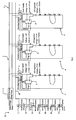
- a luminaire drive circuit 1 comprises a power supply 2 providing 24 V DC constant voltage across rails 3.
- the rails 3 provide 24V DC across a number, in this case three, LED circuits 4.
- Each LED circuit 4 comprises a p-type FET reverse polarity protection component 5, and a voltage and current controller 6 receiving 24 V DC and 271mA from the rails 3.
- the regulator 6 in turn provides a regulated voltage of 17.5V DC across LEDs 7 and a current of 350mA through them.
- the series 7 of LEDs receive the correct supply voltage of 17.5V. Also, if there is a short-circuit fault in an individual LED circuit 4 then that circuit does not draw a large current. This achieves excellent uniformity of light output across the LED circuits 4, and contributes to LED lifetime.
- the voltage and current controller 6 comprises a switch to enable current to flow from the positive supply through the LEDs to 0V, a current sensing circuit to continuously monitor the LED current, and a circuit to allow the current to be adjusted externally.
- the reverse polarity protection component 5 comprises a p-type FET with its drain connected to the positive supply, its gate connected to the negative supply. This is an efficient reverse polarity protection scheme. The source of the FET then becomes the positive power rail.
- the typical resistance of a suitable FET is 25m0hm, meaning for a 1A current Vfet is 25mV and the power loss in the protection circuitry is 0.025W. This gives a twenty fold improvement in power losses due to reverse polarity protection, compared with conventional reverse protection diodes.
- inductor L in series with the LEDs 7. This has a value of 100uH and is for supplying current to LEDs when the switch in the controller is open and there is no electrical path from the positive supply to 0V.
- the current controller closes a switch to 0V at its pin marked Lx.
- Current then starts to increase in the LEDs, with the rate of increase determined by the value of the inductor L and the supply voltage.
- the switch is opened.
- Current continues through the LEDs, but now through the Schottky diode CR and back to the positive supply rail. This current is supplied by the energy stored in the inductor L.
- the switch is once again closed and the cycle repeats itself.
- the frequency at which this cycle repeats itself varies depending on various parameters (such as the value of the inductor, the LED current, the supply voltage and the LED forward voltages) but is generally in the region of hundreds of kilohertz.
- the high efficiency throughout the range of LED forward voltages is maintained because the switching of the current path to 0V is automatically adjusted according whatever conditions prevail.
- circuit efficiency is defined as the ratio of the amount of power that is used to produce light divided by the total power delivered to the LED circuit 4. For comparison, the efficiency achieved by a linear controller carrying out the same task is also included. Table 1 Actual circuit efficiency throughout Vf range LED forward voltage Vf Circuit efficiency (Luminaire Drive Circuit) Circuit efficiency (using linear controller) 3.2V 93% 66% 3.5V 94% 73% 4.0V 96% 83%
- Controlling the current in the LEDs 7 regulates the luminous output, CRI, and colour temperature and ensures that the LEDs 7 operate within their recommended specification, thus enhancing luminaire lifetime.
- Fig. 1 also shows a bank of environment sensors and control devices 10. These are:
- Any of these devices can send a dimming control signal on a control line 18, connected to a control input of each current controller 6.
- This provides universal dimming control to all of the LED circuits 7 together, in response to any of a range of environmental conditions and user controls. This achieves very effective control, optimising electrical efficiency.
- each LED circuit 4 may comprise a bridge comprising four FETs (two p-type and two n-type) combined to form a full bridge circuit 18.
- the device powers up correctly irrespective of how the power wires were connected and a 20-fold improvement in power loss is maintained compared to prior approaches.
- the LEDs 7 are on a thin (c100 ⁇ m) PCB 30 with a high thermal conductivity, on a metal substrate 31, over a heat sink 32.
- a capacitor 33 couples the circuit 0V and the metal substrate 31.
- the capacitor is connected between the conductors 30 and the metal substrate 31 by a screw 35 electrically contacting a round track 36 (in turn contacting the capacitor 33) on the board 34 at its top, and contacting the heat sink 32 at its bottom end.
- control circuitry be located on the same PCB as the LEDs.
- This arrangement has a drawback however, because it means there is only one layer of copper available for the circuitry.
- a second electrically conducting layer underneath the circuit and directly connected to 0V (known as a ground plane) is normally present.
- the metal substrate and heatsink underneath the circuit may become electrically exposed to the environment, and so cannot be connected to the circuit 0V. Additionally, because of the proximity of the metal substrate 32 to the circuitry, externally sourced signals on this can lead to unpredictable circuit behaviour.
- the capacitor 33 provides DC separation and AC coupling between the circuit 0V and the metal substrate 31 and heatsink 32, ensuring proper operation of the circuit.
- the capacitor provides a path for conducting unwanted AC signals to 0V thereby ensuring they do not interfere with the circuit's operation.
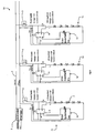
- an alternative drive circuit, 50 is illustrated, and parts similar to those of Fig. 1 are given the same reference numerals.
- an object proximity sensor 52 within each individual LED circuit 51 supplies control signals to the voltage and current controller 6.
- the sensor 52 comprises one photodiode 52 per LED chain, mounted such as to measure the amount of light reflected from the illuminated object in front of it.
- the control circuitry adjusts the light output in accordance with the signal from the photodiode.
- automatic proximity sensing control is achieved by mere use of a photodiode, as it utilises the reflectance of the emitted light by the LEDs to provide proximity information.
- the senor could comprise a dedicated proximity sensor comprising an active transmitter/receiver combination.
- a signal distinct from the luminaire illumination output is transmitted and its reflection read by the receiver in order to infer the proximity of the target object.
- transmitter/receiver technologies include infra red and ultrasonic sensors.
- a global illuminated object proximity sensor for the whole drive circuit included in the bank of sensors 10 of the embodiment of Fig. 1
- each LED circuit 51 is on a PCB segment 55 in a line of such segments as shown in Fig. 6 there is individual control for each segment 55.
- each segment can be individually controlled for a particular display cabinet shelf.
- the LED circuits 51 are in parallel and each is connected to a common power rail 3. These common lines are distributed to the electrical circuits via pins 60 of the connectors shown in Fig. 5 .
- the proximity sensors 52 are used to sense the distance from the associated LEDs 7 to the illuminated object, and the light intensity is adjusted accordingly. This ensures uniform illumination of displayed products, and optimises electrical efficiency. This enables the target objects to be illuminated evenly even though their distance from the luminaire varies continually as objects are added, removed and re-arranged. This aspect of the invention is most advantageous in a retail application where items on a shelf are being illuminated, leading to uniformity of illumination across products at varying distances from the luminaire and enabling energy savings..
- each LED circuit may include different or additional sensors for individual control of each series of LEDs.
- the temperature of the PCB could be monitored and the light output reduced if the temperature exceeds a set point. This would ensure the LED lifetime in applications where the ambient temperature can become unusually high.
- the current regulator automatically lowers LED power consumption in response to excessively high temperature of the LED circuit.
- Benefits are (i) to ensure the desired illumination level is achieved irrespective of changes in background lighting (ii) energy savings, since in the absence of the light sensor, the luminaire would generally be set to fully on.
- each LED circuit There may be multiple environmental sensors in each LED circuit, and by controlling the light according to inputs from a number of different sensor types an optimal combination of all the benefits accruing from each sensor can be achieved.
- the CRI and colour temperature of a luminaire will vary to some extent with changes in the ambient temperature. If a particular application values constant CRI and/or colour temperature above other parameters such as luminous flux, by sensing the ambient temperature the current in the luminaire can be automatically adjusted to ensure that the desired CRI and/or colour temperature are maintained.
- an optimum combination of illumination quality (uniformity, CRI and colour temperature), electrical efficiency and luminaire lifetime is achieved by using a power supply to convert mains AC to a fixed low DC voltage and individually controlling current and voltage in each of multiple LED circuits.
- the LED driving signal ensures that the current in each LED is the same, resulting in tightly controlled luminous flux, excellent uniformity of light output and luminaire lifetime. Any number of LED circuits can be added, and since each LED circuit has its own regulation circuitry, differences in individual LED characteristics become irrelevant.
- the desired colour temperature is maintained by the individual current regulation, the luminous flux output is maintained by the current regulation, the efficiency is not affected by using different LEDs, overall performance is not affected by using LEDs with different electrical characteristics.
- the invention is not limited to the embodiments described but may be varied in construction and detail.
- the proximity sensor may be of a different type, for example using ultrasonic, optical, infra-red or any other proximity sensing technology.
Landscapes
- Engineering & Computer Science (AREA)
- General Engineering & Computer Science (AREA)
- Physics & Mathematics (AREA)
- Spectroscopy & Molecular Physics (AREA)
- Circuit Arrangement For Electric Light Sources In General (AREA)
- Arrangement Of Elements, Cooling, Sealing, Or The Like Of Lighting Devices (AREA)
- Non-Portable Lighting Devices Or Systems Thereof (AREA)
Claims (17)
- Leuchtentreiberschaltung (1), die Folgendes umfasst:Gleichstromschienen (3), undmehrere LED-Treiberschaltungen (4), die an die Schienen (3) angeschlossen sind, um Gleichstromleistung zu empfangen, wobei jede LED-Treiberschaltung mehrere in Reihe geschaltete LEDs (7) umfasst und einen Spannungs- und Stromregler (6) umfasst, um den Strom durch die LEDs und die Spannung an den LEDs, die geringer ist als die Spannung an den Schienen, zu regeln,
dadurch gekennzeichnet, dassdie Leuchtentreiberschaltung weiter ein Umgebungssensormittel (10) umfasst und jeder Spannungs- und Stromregler (6) Mittel zum Reagieren auf einen Steuersignaleingang (18) von dem Sensormittel umfasst, unddas Umgebungssensormittel einen Näherungssensor (52) umfasst, um die Nähe eines beleuchteten Gegenstands abzufühlen, und mindestens ein Spannungs- und Stromregler (6) Mittel umfasst, um automatisch den LED-Strom und daher den Beleuchtungspegel gemäß der Nähe eines beleuchteten Gegenstands zu verändern. - Leuchtentreiberschaltung nach Anspruch 1, wobei jede LED-Treiberschaltung (4) ein mit einer Versorgungsschiene (5) in Reihe geschaltetes FET-Bauteil (5) umfasst, um Verpolungsschutz vorzusehen.
- Leuchtentreiberschaltung nach Anspruch 2, wobei das FET-Bauteil (5) ein p-Typ ist, der Drain des FET an einen positiven Schieneneingang angeschlossen ist und das Gate des FET an einen negativen Schieneneingang angeschlossen ist.
- Leuchtentreiberschaltung nach einem der Ansprüche 1 bis 3, weiter umfassend eine Brücke für jede LED-Treiberschaltung, wobei die Brücke vier FETs umfasst, die angeordnet sind, um sicherzustellen, dass die Schaltung ungeachtet der Versorgungspolarität einschaltet.
- Leuchtentreiberschaltung nach Ansprüchen 1-4, wobei sich die Leuchtentreiberschaltung auf einer Platine (30, 34) über einem Metallsubstrat (31), seinerseits über einer Metallwärmesenke (32) befindet.
- Leuchtentreiberschaltung nach Anspruch 5, wobei ein Kondensator (33) die Leuchtentreiberschaltung an das Metallsubstrat koppelt.
- Leuchtentreiberschaltung nach Anspruch 6, wobei der Kondensator einen Wert im Bereich von 0,001 µF bis 10 µF aufweist.
- Leuchtentreiberschaltung nach Anspruch 6 oder 7, wobei der Kondensator (33) an das obere Ende eines Schraubenbefestigungselements (35) angeschlossen ist, wobei sich das Befestigungselement durch einen isolierenden Teil (34) der Platine und zu dem Metallsubstrat (32) erstreckt.
- Leuchtentreiberschaltung nach einem der vorangehenden Ansprüche, wobei der Steuersignaleingang in einem Pulsweitenmodulations(PWM)-Format ist.
- Leuchtentreiberschaltung nach einem der vorangehenden Ansprüche, wobei der Steuersignaleingang (18) an eine globale Steuerleitung (18) angeschlossen ist und die Steuerleitung an das Umgebungssensormittel (10) angeschlossen ist.
- Leuchtentreiberschaltung nach einem der vorangehenden Ansprüche, wobei das Umgebungssensormittel einen Temperatursensor (16) umfasst und mindestens ein Spannungs- und Stromregler (6) Mittel umfasst, um die LED-Leistungsaufnahme als Reaktion auf eine übermäßig hohe Temperatur der Leuchtentreiberschaltung oder einer LED-Treiberschaltung automatisch zu senken.
- Leuchtentreiberschaltung nach einem der vorangehenden Ansprüche, wobei das Umgebungssensormittel einen Umlichtsensor (17) umfasst und mindestens ein Spannungs- und Stromregler (6) Mittel umfasst, um den Pegel der Beleuchtung gemäß dem Umlichtpegel automatisch zu regeln.
- Leuchtentreiberschaltung nach einem der vorangehenden Ansprüche, wobei das Umgebungssensormittel einen Temperatursensor (16) und einen Umlichtsensor (17) umfasst und mindestens ein Spannungs- und Stromregler Mittel umfasst, um die Gleichmäßigkeit der Beleuchtung gemäß der Kombination von Nähe eines beleuchteten Gegenstands, Temperatur und Umlicht zu regeln.
- Leuchtentreiberschaltung nach einem der vorangehenden Ansprüche, wobei der Näherungssensor eine Photodiode (52) umfasst, die dazu angebracht ist, das Ausmaß von von LEDs ausgestrahltem Licht zu erkennen, das von einem nahen beleuchteten Gegenstand reflektiert wird.
- Leuchtentreiberschaltung nach einem der vorangehenden Ansprüche, wobei für jede LED-Treiberschaltung ein eigener Umgebungssensor (52) vorgesehen ist.
- Leuchtentreiberschaltung nach einem der vorangehenden Ansprüche, wobei sich jede LED-Treiberschaltung auf einer Linearplatine (55) befindet und die Platinen durch Verbinder (60) an jedem Ende der Platine elektrisch miteinander verbunden sind.
- Leuchte, die Leuchtdioden auf einem Substrat und eine Leuchtentreiberschaltung nach einem der vorangehenden Ansprüche umfasst.
Applications Claiming Priority (3)
| Application Number | Priority Date | Filing Date | Title |
|---|---|---|---|
| IE20060767 | 2006-10-19 | ||
| IE20070459 | 2007-06-26 | ||
| PCT/IE2007/000102 WO2008047336A2 (en) | 2006-10-19 | 2007-10-18 | A luminaire drive circuit |
Publications (2)
| Publication Number | Publication Date |
|---|---|
| EP2074868A2 EP2074868A2 (de) | 2009-07-01 |
| EP2074868B1 true EP2074868B1 (de) | 2013-03-06 |
Family
ID=38895652
Family Applications (2)
| Application Number | Title | Priority Date | Filing Date |
|---|---|---|---|
| EP07827114A Withdrawn EP2076709A1 (de) | 2006-10-19 | 2007-10-18 | Verbesserungen von schaukastenleuchten |
| EP07827115A Not-in-force EP2074868B1 (de) | 2006-10-19 | 2007-10-18 | Ansteuerschaltung für eine beleuchtungsvorrichtung |
Family Applications Before (1)
| Application Number | Title | Priority Date | Filing Date |
|---|---|---|---|
| EP07827114A Withdrawn EP2076709A1 (de) | 2006-10-19 | 2007-10-18 | Verbesserungen von schaukastenleuchten |
Country Status (3)
| Country | Link |
|---|---|
| US (2) | US20100085748A1 (de) |
| EP (2) | EP2076709A1 (de) |
| WO (2) | WO2008047335A1 (de) |
Families Citing this family (54)
| Publication number | Priority date | Publication date | Assignee | Title |
|---|---|---|---|---|
| US8092251B2 (en) * | 2007-12-29 | 2012-01-10 | Apple Inc. | Active electronic media device packaging |
| US8841859B2 (en) * | 2008-04-14 | 2014-09-23 | Digital Lumens Incorporated | LED lighting methods, apparatus, and systems including rules-based sensor data logging |
| FR2930706B1 (fr) * | 2008-04-24 | 2012-11-02 | Zedel | Lampe d'eclairage autoregulee |
| US20160053977A1 (en) | 2008-09-24 | 2016-02-25 | B/E Aerospace, Inc. | Flexible led lighting element |
| EP2329186B1 (de) | 2008-09-24 | 2018-02-21 | B/E Aerospace Inc. | Flugzeug-led-scheinwerfersystem und steuerungsverfahren dafür |
| EP2347636B1 (de) | 2008-10-17 | 2014-03-12 | Koninklijke Philips N.V. | Verfahren und vorrichtung zum steuern eines beleuchtungssystems in einer temperaturgeregelten umgebung |
| WO2010106470A1 (en) * | 2009-03-18 | 2010-09-23 | Koninklijke Philips Electronics N.V. | Lighting system for a freezer cabinet and/or a refrigerator cabinet |
| US20100245279A1 (en) * | 2009-03-31 | 2010-09-30 | Robe Lighting S.R.O. | Display and display control system for an automated luminaire |
| DE102009002775A1 (de) * | 2009-04-30 | 2010-11-04 | BSH Bosch und Siemens Hausgeräte GmbH | Lampe für Hausgerät sowie Hausgerät, insbesondere zum Zubereiten von Lebensmitteln, mit einer Lampe |
| US8109647B2 (en) | 2009-07-28 | 2012-02-07 | Lg Innotek Co., Ltd. | Lighting device |
| EP2280213B1 (de) * | 2009-07-28 | 2016-04-06 | LG Innotek Co., Ltd. | Beleuchtungsvorrichtung |
| EP2462375B1 (de) * | 2009-08-04 | 2015-09-30 | Bruce Aerospace, Inc. | Led-leuchte von hoher helligkeit |
| US10264637B2 (en) | 2009-09-24 | 2019-04-16 | Cree, Inc. | Solid state lighting apparatus with compensation bypass circuits and methods of operation thereof |
| US9713211B2 (en) * | 2009-09-24 | 2017-07-18 | Cree, Inc. | Solid state lighting apparatus with controllable bypass circuits and methods of operation thereof |
| US8901845B2 (en) | 2009-09-24 | 2014-12-02 | Cree, Inc. | Temperature responsive control for lighting apparatus including light emitting devices providing different chromaticities and related methods |
| CA2778983A1 (en) | 2009-10-27 | 2011-05-05 | GE Lighting Solutions, LLC | Refractive optics to provide uniform illumination in a display case |
| WO2011106661A1 (en) | 2010-02-25 | 2011-09-01 | B/E Aerospace, Inc. | Calibration method for led lighting systems |
| JP2013521594A (ja) * | 2010-02-25 | 2013-06-10 | ビーイー・エアロスペース・インコーポレーテッド | Led照明素子 |
| DE102010031244B4 (de) * | 2010-03-19 | 2023-01-12 | Tridonic Ag | Modulares LED-Beleuchtungssystem |
| US8476836B2 (en) | 2010-05-07 | 2013-07-02 | Cree, Inc. | AC driven solid state lighting apparatus with LED string including switched segments |
| US8376583B2 (en) * | 2010-05-17 | 2013-02-19 | Orion Energy Systems, Inc. | Lighting system with customized intensity and profile |
| EP2614299A1 (de) | 2010-09-10 | 2013-07-17 | Nualight Limited | Beleuchter |
| US9408280B2 (en) * | 2011-05-11 | 2016-08-02 | Schreder | Lighting systems |
| US9839083B2 (en) | 2011-06-03 | 2017-12-05 | Cree, Inc. | Solid state lighting apparatus and circuits including LED segments configured for targeted spectral power distribution and methods of operating the same |
| CA2745132A1 (en) * | 2011-06-30 | 2012-12-30 | Groupe Ledel Inc. | Lamppost head assembly |
| US8641234B2 (en) | 2011-06-30 | 2014-02-04 | Groupe Ledel Inc. | Lamppost head assembly with adjustable LED heat sink support |
| US8742671B2 (en) | 2011-07-28 | 2014-06-03 | Cree, Inc. | Solid state lighting apparatus and methods using integrated driver circuitry |
| WO2013030814A2 (en) | 2011-08-30 | 2013-03-07 | Nualight Limited | A display cabinet luminaire with directional illumination |
| WO2013056012A1 (en) | 2011-10-12 | 2013-04-18 | B/E Aerospace, Inc. | Methods, apparatus and articles of manufacture to calibrate lighting units |
| US9192008B2 (en) | 2012-03-26 | 2015-11-17 | B/E Aerospace, Inc. | Reduced-size modular LED washlight component |
| WO2014005321A1 (en) * | 2012-07-06 | 2014-01-09 | GE Lighting Solutions, LLC | Linear light fixture |
| US9066405B2 (en) * | 2012-07-30 | 2015-06-23 | Cree, Inc. | Lighting device with variable color rendering based on ambient light |
| US8974077B2 (en) | 2012-07-30 | 2015-03-10 | Ultravision Technologies, Llc | Heat sink for LED light source |
| NL2010358C2 (nl) * | 2013-02-25 | 2014-08-26 | Estem B V | Led armatuur. |
| US8888349B1 (en) * | 2013-08-08 | 2014-11-18 | Osram Sylvania Inc. | LED lamp with concave reflector for poster display case |
| USD780362S1 (en) | 2013-12-09 | 2017-02-28 | Kenall Manufacturing Company | Lighting fixture |
| US9310066B2 (en) | 2013-12-09 | 2016-04-12 | Kenall Manufacturing Company | Electronic component for an improved lighting system |
| USD732225S1 (en) | 2013-12-09 | 2015-06-16 | Kenall Manufacturing Company | Lighting fixture |
| USD742581S1 (en) | 2013-12-09 | 2015-11-03 | Kenall Manufacturing Company | Driver housing |
| US9562627B2 (en) | 2013-12-09 | 2017-02-07 | Kenall Manufacturing Company | Luminaire and improved lighting system |
| US8882532B1 (en) | 2013-12-09 | 2014-11-11 | Kenall Manufacturing Company | Driver box for an improved lighting system |
| US9195281B2 (en) | 2013-12-31 | 2015-11-24 | Ultravision Technologies, Llc | System and method for a modular multi-panel display |
| USD733960S1 (en) * | 2014-02-18 | 2015-07-07 | Southpac Trust International Inc. | Light fixture lens with elevated strip features |
| JP6549603B2 (ja) * | 2014-02-28 | 2019-07-24 | シグニファイ ホールディング ビー ヴィ | 反射光に基づき光出力を較正するための方法及び装置 |
| DE102014009552A1 (de) * | 2014-06-12 | 2015-04-09 | Diehl Aerospace Gmbh | Leuchtvorrichtung zum homogenen Beleuchten einer Fläche |
| USD749774S1 (en) * | 2014-12-03 | 2016-02-16 | Anthony I. Provitola | Reflector for hidden light strip |
| WO2016102512A1 (en) * | 2014-12-22 | 2016-06-30 | Nualight Limited | A refrigerator led illuminator with tubular housing and internal lens |
| WO2016102012A1 (en) * | 2014-12-23 | 2016-06-30 | Carrier Corporation | Refrigerated sales furniture |
| CN106439566B (zh) * | 2016-11-22 | 2024-05-31 | 赛尔富电子有限公司 | 一种led条形灯具 |
| US10551039B2 (en) * | 2017-01-31 | 2020-02-04 | Scott David Moore | Removable mounting device and packaging system for lighting product |
| CN107567147B (zh) * | 2017-09-29 | 2019-08-27 | 广州市浩洋电子股份有限公司 | 一种用于舞台灯的以太网灯光控制系统及方法 |
| CN110056794B (zh) * | 2019-04-19 | 2023-10-20 | 赛尔富电子有限公司 | 一种条形灯具 |
| CN109973850A (zh) | 2019-04-19 | 2019-07-05 | 赛尔富电子有限公司 | 一种线光源照明灯 |
| RU194528U1 (ru) * | 2019-10-17 | 2019-12-13 | Акционерное общество "Федеральный центр науки и высоких технологий "Специальное научно-производственное объединение "Элерон" (АО "ФЦНИВТ "СНПО "Элерон") | Импульсный источник питания для светодиодных светильников |
Family Cites Families (24)
| Publication number | Priority date | Publication date | Assignee | Title |
|---|---|---|---|---|
| DE3235250C3 (de) * | 1982-09-23 | 1996-04-25 | Maul & Partner Gmbh Wirtschaft | Facettenoptik zum Erfassen von Strahlung aus einem großen Raumwinkel, insbesondere für Bewegungsmelder |
| US5268833A (en) * | 1991-05-14 | 1993-12-07 | U.S. Philips Corporation | Rectifier circuit including FETs of the same conductivity type |
| US5895111A (en) * | 1992-04-08 | 1999-04-20 | Anthony's Manufacturing Company, Inc. | Display case with lens lighting system |
| US5676453A (en) * | 1992-04-16 | 1997-10-14 | Tir Technologies, Inc. | Collimating TIR lens devices employing fluorescent light sources |
| US5471372A (en) * | 1993-12-06 | 1995-11-28 | Ardco, Inc. | Lighting system for commercial refrigerator doors |
| US7161313B2 (en) * | 1997-08-26 | 2007-01-09 | Color Kinetics Incorporated | Light emitting diode based products |
| US6528954B1 (en) * | 1997-08-26 | 2003-03-04 | Color Kinetics Incorporated | Smart light bulb |
| AU5632800A (en) * | 1999-06-25 | 2001-01-31 | Anthony, Inc. | Lighting system for display cabinet |
| US6424096B1 (en) * | 2000-04-18 | 2002-07-23 | Donovan S. Lowe | Remotely controlled light displays |
| US7121675B2 (en) * | 2002-01-10 | 2006-10-17 | Artak Ter-Hovhannisian | Low temperature LED lighting system |
| US7116294B2 (en) | 2003-02-07 | 2006-10-03 | Whelen Engineering Company, Inc. | LED driver circuits |
| US7615939B2 (en) * | 2003-03-17 | 2009-11-10 | C&D Zodiac, Inc. | Spectrally calibratable multi-element RGB LED light source |
| US7528421B2 (en) * | 2003-05-05 | 2009-05-05 | Lamina Lighting, Inc. | Surface mountable light emitting diode assemblies packaged for high temperature operation |
| US7163305B2 (en) * | 2003-06-25 | 2007-01-16 | Gemtron Corporation | Illuminated shelf |
| US7019662B2 (en) * | 2003-07-29 | 2006-03-28 | Universal Lighting Technologies, Inc. | LED drive for generating constant light output |
| CN1956668B (zh) * | 2004-05-26 | 2012-02-29 | 吉尔科有限公司 | 用于产品陈列柜的led照明系统 |
| DE102004042854A1 (de) * | 2004-08-18 | 2006-02-23 | Aldi Einkauf Gmbh & Co. Ohg | Warenpräsentationsbehälter, insbesondere Kühltheke |
| ES2557159T3 (es) * | 2004-12-23 | 2016-01-22 | Nualight Limited | Iluminación de vitrina de exposición |
| US7543956B2 (en) * | 2005-02-28 | 2009-06-09 | Philips Solid-State Lighting Solutions, Inc. | Configurations and methods for embedding electronics or light emitters in manufactured materials |
| CN100585268C (zh) * | 2005-03-07 | 2010-01-27 | 日亚化学工业株式会社 | 面状照射光源及面状照射装置 |
| US8235539B2 (en) * | 2006-06-30 | 2012-08-07 | Electraled, Inc. | Elongated LED lighting fixture |
| JP2010516016A (ja) * | 2006-10-06 | 2010-05-13 | キュー テクノロジー,インコーポレイテッド | 一様な照明または勾配のある照明を達成するための多重配置光源 |
| DE602007007804D1 (de) * | 2006-11-10 | 2010-08-26 | Philips Solid State Lighting | Verfahren und vorrichtung zur steuerung von hintereinandergeschalteten led |
| US7559672B1 (en) * | 2007-06-01 | 2009-07-14 | Inteled Corporation | Linear illumination lens with Fresnel facets |
-
2007
- 2007-10-18 US US12/311,903 patent/US20100085748A1/en not_active Abandoned
- 2007-10-18 WO PCT/IE2007/000101 patent/WO2008047335A1/en not_active Ceased
- 2007-10-18 US US12/311,939 patent/US20100026187A1/en not_active Abandoned
- 2007-10-18 WO PCT/IE2007/000102 patent/WO2008047336A2/en not_active Ceased
- 2007-10-18 EP EP07827114A patent/EP2076709A1/de not_active Withdrawn
- 2007-10-18 EP EP07827115A patent/EP2074868B1/de not_active Not-in-force
Also Published As
| Publication number | Publication date |
|---|---|
| IE20070759A1 (en) | 2008-06-11 |
| WO2008047335A1 (en) | 2008-04-24 |
| IE20070758A1 (en) | 2008-06-11 |
| WO2008047336A2 (en) | 2008-04-24 |
| EP2076709A1 (de) | 2009-07-08 |
| EP2074868A2 (de) | 2009-07-01 |
| US20100026187A1 (en) | 2010-02-04 |
| WO2008047336A3 (en) | 2008-06-05 |
| US20100085748A1 (en) | 2010-04-08 |
Similar Documents
| Publication | Publication Date | Title |
|---|---|---|
| EP2074868B1 (de) | Ansteuerschaltung für eine beleuchtungsvorrichtung | |
| US10051706B2 (en) | Current splitter for LED lighting system | |
| US9072149B2 (en) | LED driving device with open circuit protection and color temperature and brightness adjustment | |
| JP5433068B2 (ja) | 可変電圧ブースト電流源を有する固体照明パネル | |
| US8941331B2 (en) | Solid state lighting panels with variable voltage boost current sources | |
| US20110025230A1 (en) | Driver device for leds | |
| US9763298B2 (en) | Voltage balancing current controlled LED circuit | |
| US20050151708A1 (en) | LED module with uniform LED brightness | |
| KR20110092156A (ko) | 엘이디 조명등 제어시스템 | |
| TWM451467U (zh) | 具有自動調光模組之省電照明裝置 | |
| CN101222798B (zh) | 发光二极管的驱动电路 | |
| IE85119B1 (en) | A luminaire drive circuit | |
| KR100850249B1 (ko) | 조광장치 | |
| CN102958254A (zh) | 用于led照明系统中电子变压器的负载补偿 | |
| Scheidegger et al. | DC/DC converter for commercial refrigeration LED lighting |
Legal Events
| Date | Code | Title | Description |
|---|---|---|---|
| PUAI | Public reference made under article 153(3) epc to a published international application that has entered the european phase |
Free format text: ORIGINAL CODE: 0009012 |
|
| 17P | Request for examination filed |
Effective date: 20090422 |
|
| AK | Designated contracting states |
Kind code of ref document: A2 Designated state(s): AT BE BG CH CY CZ DE DK EE ES FI FR GB GR HU IE IS IT LI LT LU LV MC MT NL PL PT RO SE SI SK TR |
|
| AX | Request for extension of the european patent |
Extension state: AL BA HR MK RS |
|
| DAX | Request for extension of the european patent (deleted) | ||
| 17Q | First examination report despatched |
Effective date: 20101014 |
|
| REG | Reference to a national code |
Ref country code: DE Ref legal event code: R079 Ref document number: 602007028933 Country of ref document: DE Free format text: PREVIOUS MAIN CLASS: H05B0033080000 Ipc: F21S0002000000 |
|
| RIC1 | Information provided on ipc code assigned before grant |
Ipc: F21S 4/00 20060101ALI20120413BHEP Ipc: F21V 21/088 20060101ALI20120413BHEP Ipc: H05B 33/08 20060101ALI20120413BHEP Ipc: A47F 11/10 20060101ALI20120413BHEP Ipc: F21V 5/04 20060101ALI20120413BHEP Ipc: F21V 9/08 20060101ALI20120413BHEP Ipc: A47F 3/00 20060101ALI20120413BHEP Ipc: F21S 2/00 20060101AFI20120413BHEP Ipc: F21V 21/02 20060101ALI20120413BHEP Ipc: F21V 7/00 20060101ALI20120413BHEP |
|
| GRAP | Despatch of communication of intention to grant a patent |
Free format text: ORIGINAL CODE: EPIDOSNIGR1 |
|
| GRAS | Grant fee paid |
Free format text: ORIGINAL CODE: EPIDOSNIGR3 |
|
| GRAA | (expected) grant |
Free format text: ORIGINAL CODE: 0009210 |
|
| AK | Designated contracting states |
Kind code of ref document: B1 Designated state(s): AT BE BG CH CY CZ DE DK EE ES FI FR GB GR HU IE IS IT LI LT LU LV MC MT NL PL PT RO SE SI SK TR |
|
| REG | Reference to a national code |
Ref country code: GB Ref legal event code: FG4D |
|
| REG | Reference to a national code |
Ref country code: CH Ref legal event code: NV Representative=s name: ISLER AND PEDRAZZINI AG, CH Ref country code: AT Ref legal event code: REF Ref document number: 599846 Country of ref document: AT Kind code of ref document: T Effective date: 20130315 Ref country code: CH Ref legal event code: EP |
|
| REG | Reference to a national code |
Ref country code: IE Ref legal event code: FG4D |
|
| REG | Reference to a national code |
Ref country code: NL Ref legal event code: T3 |
|
| REG | Reference to a national code |
Ref country code: DE Ref legal event code: R096 Ref document number: 602007028933 Country of ref document: DE Effective date: 20130502 |
|
| REG | Reference to a national code |
Ref country code: AT Ref legal event code: MK05 Ref document number: 599846 Country of ref document: AT Kind code of ref document: T Effective date: 20130306 |
|
| PG25 | Lapsed in a contracting state [announced via postgrant information from national office to epo] |
Ref country code: AT Free format text: LAPSE BECAUSE OF FAILURE TO SUBMIT A TRANSLATION OF THE DESCRIPTION OR TO PAY THE FEE WITHIN THE PRESCRIBED TIME-LIMIT Effective date: 20130306 Ref country code: SE Free format text: LAPSE BECAUSE OF FAILURE TO SUBMIT A TRANSLATION OF THE DESCRIPTION OR TO PAY THE FEE WITHIN THE PRESCRIBED TIME-LIMIT Effective date: 20130306 Ref country code: ES Free format text: LAPSE BECAUSE OF FAILURE TO SUBMIT A TRANSLATION OF THE DESCRIPTION OR TO PAY THE FEE WITHIN THE PRESCRIBED TIME-LIMIT Effective date: 20130617 Ref country code: LT Free format text: LAPSE BECAUSE OF FAILURE TO SUBMIT A TRANSLATION OF THE DESCRIPTION OR TO PAY THE FEE WITHIN THE PRESCRIBED TIME-LIMIT Effective date: 20130306 Ref country code: BG Free format text: LAPSE BECAUSE OF FAILURE TO SUBMIT A TRANSLATION OF THE DESCRIPTION OR TO PAY THE FEE WITHIN THE PRESCRIBED TIME-LIMIT Effective date: 20130606 |
|
| REG | Reference to a national code |
Ref country code: LT Ref legal event code: MG4D |
|
| PG25 | Lapsed in a contracting state [announced via postgrant information from national office to epo] |
Ref country code: GR Free format text: LAPSE BECAUSE OF FAILURE TO SUBMIT A TRANSLATION OF THE DESCRIPTION OR TO PAY THE FEE WITHIN THE PRESCRIBED TIME-LIMIT Effective date: 20130607 Ref country code: SI Free format text: LAPSE BECAUSE OF FAILURE TO SUBMIT A TRANSLATION OF THE DESCRIPTION OR TO PAY THE FEE WITHIN THE PRESCRIBED TIME-LIMIT Effective date: 20130306 Ref country code: FI Free format text: LAPSE BECAUSE OF FAILURE TO SUBMIT A TRANSLATION OF THE DESCRIPTION OR TO PAY THE FEE WITHIN THE PRESCRIBED TIME-LIMIT Effective date: 20130306 Ref country code: LV Free format text: LAPSE BECAUSE OF FAILURE TO SUBMIT A TRANSLATION OF THE DESCRIPTION OR TO PAY THE FEE WITHIN THE PRESCRIBED TIME-LIMIT Effective date: 20130306 |
|
| PG25 | Lapsed in a contracting state [announced via postgrant information from national office to epo] |
Ref country code: BE Free format text: LAPSE BECAUSE OF FAILURE TO SUBMIT A TRANSLATION OF THE DESCRIPTION OR TO PAY THE FEE WITHIN THE PRESCRIBED TIME-LIMIT Effective date: 20130306 |
|
| PG25 | Lapsed in a contracting state [announced via postgrant information from national office to epo] |
Ref country code: PT Free format text: LAPSE BECAUSE OF FAILURE TO SUBMIT A TRANSLATION OF THE DESCRIPTION OR TO PAY THE FEE WITHIN THE PRESCRIBED TIME-LIMIT Effective date: 20130708 Ref country code: IS Free format text: LAPSE BECAUSE OF FAILURE TO SUBMIT A TRANSLATION OF THE DESCRIPTION OR TO PAY THE FEE WITHIN THE PRESCRIBED TIME-LIMIT Effective date: 20130706 Ref country code: SK Free format text: LAPSE BECAUSE OF FAILURE TO SUBMIT A TRANSLATION OF THE DESCRIPTION OR TO PAY THE FEE WITHIN THE PRESCRIBED TIME-LIMIT Effective date: 20130306 Ref country code: RO Free format text: LAPSE BECAUSE OF FAILURE TO SUBMIT A TRANSLATION OF THE DESCRIPTION OR TO PAY THE FEE WITHIN THE PRESCRIBED TIME-LIMIT Effective date: 20130306 Ref country code: EE Free format text: LAPSE BECAUSE OF FAILURE TO SUBMIT A TRANSLATION OF THE DESCRIPTION OR TO PAY THE FEE WITHIN THE PRESCRIBED TIME-LIMIT Effective date: 20130306 Ref country code: CZ Free format text: LAPSE BECAUSE OF FAILURE TO SUBMIT A TRANSLATION OF THE DESCRIPTION OR TO PAY THE FEE WITHIN THE PRESCRIBED TIME-LIMIT Effective date: 20130306 |
|
| PG25 | Lapsed in a contracting state [announced via postgrant information from national office to epo] |
Ref country code: PL Free format text: LAPSE BECAUSE OF FAILURE TO SUBMIT A TRANSLATION OF THE DESCRIPTION OR TO PAY THE FEE WITHIN THE PRESCRIBED TIME-LIMIT Effective date: 20130306 Ref country code: CY Free format text: LAPSE BECAUSE OF FAILURE TO SUBMIT A TRANSLATION OF THE DESCRIPTION OR TO PAY THE FEE WITHIN THE PRESCRIBED TIME-LIMIT Effective date: 20130306 |
|
| PLBE | No opposition filed within time limit |
Free format text: ORIGINAL CODE: 0009261 |
|
| STAA | Information on the status of an ep patent application or granted ep patent |
Free format text: STATUS: NO OPPOSITION FILED WITHIN TIME LIMIT |
|
| PG25 | Lapsed in a contracting state [announced via postgrant information from national office to epo] |
Ref country code: DK Free format text: LAPSE BECAUSE OF FAILURE TO SUBMIT A TRANSLATION OF THE DESCRIPTION OR TO PAY THE FEE WITHIN THE PRESCRIBED TIME-LIMIT Effective date: 20130306 |
|
| 26N | No opposition filed |
Effective date: 20131209 |
|
| PG25 | Lapsed in a contracting state [announced via postgrant information from national office to epo] |
Ref country code: IT Free format text: LAPSE BECAUSE OF FAILURE TO SUBMIT A TRANSLATION OF THE DESCRIPTION OR TO PAY THE FEE WITHIN THE PRESCRIBED TIME-LIMIT Effective date: 20130306 |
|
| REG | Reference to a national code |
Ref country code: DE Ref legal event code: R097 Ref document number: 602007028933 Country of ref document: DE Effective date: 20131209 |
|
| PG25 | Lapsed in a contracting state [announced via postgrant information from national office to epo] |
Ref country code: MC Free format text: LAPSE BECAUSE OF FAILURE TO SUBMIT A TRANSLATION OF THE DESCRIPTION OR TO PAY THE FEE WITHIN THE PRESCRIBED TIME-LIMIT Effective date: 20130306 |
|
| PG25 | Lapsed in a contracting state [announced via postgrant information from national office to epo] |
Ref country code: TR Free format text: LAPSE BECAUSE OF FAILURE TO SUBMIT A TRANSLATION OF THE DESCRIPTION OR TO PAY THE FEE WITHIN THE PRESCRIBED TIME-LIMIT Effective date: 20130306 |
|
| PG25 | Lapsed in a contracting state [announced via postgrant information from national office to epo] |
Ref country code: LU Free format text: LAPSE BECAUSE OF NON-PAYMENT OF DUE FEES Effective date: 20131018 Ref country code: HU Free format text: LAPSE BECAUSE OF FAILURE TO SUBMIT A TRANSLATION OF THE DESCRIPTION OR TO PAY THE FEE WITHIN THE PRESCRIBED TIME-LIMIT; INVALID AB INITIO Effective date: 20071018 |
|
| PG25 | Lapsed in a contracting state [announced via postgrant information from national office to epo] |
Ref country code: MT Free format text: LAPSE BECAUSE OF FAILURE TO SUBMIT A TRANSLATION OF THE DESCRIPTION OR TO PAY THE FEE WITHIN THE PRESCRIBED TIME-LIMIT Effective date: 20130306 |
|
| REG | Reference to a national code |
Ref country code: FR Ref legal event code: PLFP Year of fee payment: 9 |
|
| REG | Reference to a national code |
Ref country code: FR Ref legal event code: PLFP Year of fee payment: 10 |
|
| REG | Reference to a national code |
Ref country code: FR Ref legal event code: PLFP Year of fee payment: 11 |
|
| PGFP | Annual fee paid to national office [announced via postgrant information from national office to epo] |
Ref country code: GB Payment date: 20170919 Year of fee payment: 11 Ref country code: CH Payment date: 20170920 Year of fee payment: 11 Ref country code: FR Payment date: 20170929 Year of fee payment: 11 |
|
| PGFP | Annual fee paid to national office [announced via postgrant information from national office to epo] |
Ref country code: IE Payment date: 20170919 Year of fee payment: 11 |
|
| PGFP | Annual fee paid to national office [announced via postgrant information from national office to epo] |
Ref country code: DE Payment date: 20171005 Year of fee payment: 11 |
|
| PGFP | Annual fee paid to national office [announced via postgrant information from national office to epo] |
Ref country code: NL Payment date: 20171030 Year of fee payment: 11 |
|
| REG | Reference to a national code |
Ref country code: DE Ref legal event code: R119 Ref document number: 602007028933 Country of ref document: DE |
|
| REG | Reference to a national code |
Ref country code: CH Ref legal event code: PL |
|
| REG | Reference to a national code |
Ref country code: NL Ref legal event code: MM Effective date: 20181101 |
|
| GBPC | Gb: european patent ceased through non-payment of renewal fee |
Effective date: 20181018 |
|
| REG | Reference to a national code |
Ref country code: IE Ref legal event code: MM4A |
|
| PG25 | Lapsed in a contracting state [announced via postgrant information from national office to epo] |
Ref country code: NL Free format text: LAPSE BECAUSE OF NON-PAYMENT OF DUE FEES Effective date: 20181101 Ref country code: DE Free format text: LAPSE BECAUSE OF NON-PAYMENT OF DUE FEES Effective date: 20190501 |
|
| PG25 | Lapsed in a contracting state [announced via postgrant information from national office to epo] |
Ref country code: LI Free format text: LAPSE BECAUSE OF NON-PAYMENT OF DUE FEES Effective date: 20181031 Ref country code: FR Free format text: LAPSE BECAUSE OF NON-PAYMENT OF DUE FEES Effective date: 20181031 Ref country code: CH Free format text: LAPSE BECAUSE OF NON-PAYMENT OF DUE FEES Effective date: 20181031 |
|
| PG25 | Lapsed in a contracting state [announced via postgrant information from national office to epo] |
Ref country code: IE Free format text: LAPSE BECAUSE OF NON-PAYMENT OF DUE FEES Effective date: 20181018 Ref country code: GB Free format text: LAPSE BECAUSE OF NON-PAYMENT OF DUE FEES Effective date: 20181018 |