EP2074959B1 - Chirurgische Operationsvorrichtung - Google Patents
Chirurgische Operationsvorrichtung Download PDFInfo
- Publication number
- EP2074959B1 EP2074959B1 EP08016451A EP08016451A EP2074959B1 EP 2074959 B1 EP2074959 B1 EP 2074959B1 EP 08016451 A EP08016451 A EP 08016451A EP 08016451 A EP08016451 A EP 08016451A EP 2074959 B1 EP2074959 B1 EP 2074959B1
- Authority
- EP
- European Patent Office
- Prior art keywords
- distal end
- end portion
- jaw
- probe
- unit
- Prior art date
- Legal status (The legal status is an assumption and is not a legal conclusion. Google has not performed a legal analysis and makes no representation as to the accuracy of the status listed.)
- Active
Links
Images


Classifications
-
- A—HUMAN NECESSITIES
- A61—MEDICAL OR VETERINARY SCIENCE; HYGIENE
- A61B—DIAGNOSIS; SURGERY; IDENTIFICATION
- A61B18/00—Surgical instruments, devices or methods for transferring non-mechanical forms of energy to or from the body
- A61B18/04—Surgical instruments, devices or methods for transferring non-mechanical forms of energy to or from the body by heating
- A61B18/12—Surgical instruments, devices or methods for transferring non-mechanical forms of energy to or from the body by heating by passing a current through the tissue to be heated, e.g. high-frequency current
-
- A—HUMAN NECESSITIES
- A61—MEDICAL OR VETERINARY SCIENCE; HYGIENE
- A61B—DIAGNOSIS; SURGERY; IDENTIFICATION
- A61B17/00—Surgical instruments, devices or methods
- A61B17/32—Surgical cutting instruments
- A61B17/320068—Surgical cutting instruments using mechanical vibrations, e.g. ultrasonic
- A61B17/320092—Surgical cutting instruments using mechanical vibrations, e.g. ultrasonic with additional movable means for clamping or cutting tissue, e.g. with a pivoting jaw
-
- A—HUMAN NECESSITIES
- A61—MEDICAL OR VETERINARY SCIENCE; HYGIENE
- A61B—DIAGNOSIS; SURGERY; IDENTIFICATION
- A61B17/00—Surgical instruments, devices or methods
- A61B17/32—Surgical cutting instruments
-
- A—HUMAN NECESSITIES
- A61—MEDICAL OR VETERINARY SCIENCE; HYGIENE
- A61B—DIAGNOSIS; SURGERY; IDENTIFICATION
- A61B17/00—Surgical instruments, devices or methods
- A61B17/34—Trocars; Puncturing needles
-
- A—HUMAN NECESSITIES
- A61—MEDICAL OR VETERINARY SCIENCE; HYGIENE
- A61B—DIAGNOSIS; SURGERY; IDENTIFICATION
- A61B18/00—Surgical instruments, devices or methods for transferring non-mechanical forms of energy to or from the body
- A61B18/04—Surgical instruments, devices or methods for transferring non-mechanical forms of energy to or from the body by heating
- A61B18/12—Surgical instruments, devices or methods for transferring non-mechanical forms of energy to or from the body by heating by passing a current through the tissue to be heated, e.g. high-frequency current
- A61B18/14—Probes or electrodes therefor
- A61B18/1442—Probes having pivoting end effectors, e.g. forceps
- A61B18/1445—Probes having pivoting end effectors, e.g. forceps at the distal end of a shaft, e.g. forceps or scissors at the end of a rigid rod
-
- A—HUMAN NECESSITIES
- A61—MEDICAL OR VETERINARY SCIENCE; HYGIENE
- A61B—DIAGNOSIS; SURGERY; IDENTIFICATION
- A61B17/00—Surgical instruments, devices or methods
- A61B17/28—Surgical forceps
- A61B17/29—Forceps for use in minimally invasive surgery
- A61B17/2909—Handles
- A61B2017/2925—Pistol grips
-
- A—HUMAN NECESSITIES
- A61—MEDICAL OR VETERINARY SCIENCE; HYGIENE
- A61B—DIAGNOSIS; SURGERY; IDENTIFICATION
- A61B17/00—Surgical instruments, devices or methods
- A61B17/32—Surgical cutting instruments
- A61B17/320068—Surgical cutting instruments using mechanical vibrations, e.g. ultrasonic
- A61B17/320092—Surgical cutting instruments using mechanical vibrations, e.g. ultrasonic with additional movable means for clamping or cutting tissue, e.g. with a pivoting jaw
- A61B2017/320093—Surgical cutting instruments using mechanical vibrations, e.g. ultrasonic with additional movable means for clamping or cutting tissue, e.g. with a pivoting jaw additional movable means performing cutting operation
-
- A—HUMAN NECESSITIES
- A61—MEDICAL OR VETERINARY SCIENCE; HYGIENE
- A61B—DIAGNOSIS; SURGERY; IDENTIFICATION
- A61B17/00—Surgical instruments, devices or methods
- A61B17/32—Surgical cutting instruments
- A61B17/320068—Surgical cutting instruments using mechanical vibrations, e.g. ultrasonic
- A61B17/320092—Surgical cutting instruments using mechanical vibrations, e.g. ultrasonic with additional movable means for clamping or cutting tissue, e.g. with a pivoting jaw
- A61B2017/320094—Surgical cutting instruments using mechanical vibrations, e.g. ultrasonic with additional movable means for clamping or cutting tissue, e.g. with a pivoting jaw additional movable means performing clamping operation
-
- A—HUMAN NECESSITIES
- A61—MEDICAL OR VETERINARY SCIENCE; HYGIENE
- A61B—DIAGNOSIS; SURGERY; IDENTIFICATION
- A61B17/00—Surgical instruments, devices or methods
- A61B17/32—Surgical cutting instruments
- A61B17/320068—Surgical cutting instruments using mechanical vibrations, e.g. ultrasonic
- A61B17/320092—Surgical cutting instruments using mechanical vibrations, e.g. ultrasonic with additional movable means for clamping or cutting tissue, e.g. with a pivoting jaw
- A61B2017/320095—Surgical cutting instruments using mechanical vibrations, e.g. ultrasonic with additional movable means for clamping or cutting tissue, e.g. with a pivoting jaw with sealing or cauterizing means
Definitions
- the present invention relates to a surgical operating apparatus which performs therapeutic treatment, such as incision, resection or coagulation, of a living body tissue by making use of ultrasonic and composite energy of ultrasonic and high-frequency waves.
- Patent Document 1 Jpn. Pat. Appln. KOKAI Publication No. 2006-223741 (Patent Document 1), for instance, discloses an ultrasonic therapeutic apparatus as a general example of an ultrasonic therapeutic apparatus which can perform therapeutic treatment, such as incision, resection or coagulation, of a living body tissue by making use of ultrasonic and can also perform therapeutic treatment by high-frequency waves.
- a proximal-side operation section is coupled to a proximal end portion of an elongated insertion section.
- An ultrasonic transducer which generates ultrasonic vibration is provided in the operation section.
- a therapeutic section for treating a living body tissue is provided at a distal end portion of the insertion section.
- the insertion section has an elongated tubular sheath.
- a rod-shaped vibration transmission member (probe) is inserted in the sheath.
- a proximal end portion of the vibration transmission member is detachably attached to the ultrasonic transducer via a screw-type coupling section.
- Ultrasonic vibration which is generated by the ultrasonic transducer, is transmitted to a probe distal end portion at the distal end side of the vibration transmission member.
- a jaw In the therapeutic section, a jaw is disposed to be opposed to the probe distal end portion. A proximal end portion of the jaw is rotatably supported on a distal end portion of the sheath via a support shaft. An operation rod for driving the jaw is inserted in the sheath so as to be axially advancible/retreatable.
- the operation section is provided with an operation handle. In accordance with the operation of the operation handle, the operation rod is axially advanced/retreated. In interlock with the operation of the operation rod, the jaw is opened/closed relative the probe distal end portion.
- a living body tissue is held between the probe distal end portion and the jaw in accordance with the closing operation of the jaw.
- ultrasonic vibration from the ultrasonic transducer is transmitted to the probe distal end portion on the therapeutic section side via the vibration transmission member.
- therapeutic treatment such as incision, resection or coagulation, of the living body tissue is performed.
- a proximal end portion of the sheath is detachably coupled to the operation handle of the operation section. Further, a high-frequency connection pin is attached to the operation section. An electric cord for supplying high-frequency current from a high-frequency cauterization power supply device is connected to the high-frequency connection pin. An inner end portion of the high-frequency connection pin is electrically connected to the probe distal end portion of the therapeutic section or to the jaw via an electric conduction path within the operation section and the sheath. High-frequency current is supplied, when necessary, to the probe distal end portion of the therapeutic section or to the jaw, and high-frequency therapeutic treatment, such as coagulation, of the living body tissue is performed.
- Patent Document 2 Jpn. Pat. Appln. KOKAI Publication No. 2007-50181 discloses an apparatus in which an ultrasonic therapeutic apparatus is combined with a high-frequency therapeutic device of a so-called bipolar type in which a pair of electrodes for high-frequency therapeutic treatment are assembled.
- a first electrode section of the pair of electrodes is formed at a probe distal end portion of the treatment section and the other electrode section of the pair of electrodes is provided on the jaw.
- the jaw is provided with an insulation member which secures a clearance between the second electrode section and the probe distal end portion.
- the present invention has been made in consideration of the above-described circumstances, and the object of the invention is to provide a surgical operating apparatus in which a clearance between an electrode section of a probe distal end portion and an electrode section of a jaw can be secured, and a manufacturing error of each part of the apparatus, an assembly error, etc. can easily be managed.
- US 2007/0043297 A1 relates to an ultrasonic coagulation and cutting apparatus including: an ultrasonic transducer for a treatment using ultrasonic vibrations on body tissue; a probe for transmitting generated ultrasonic vibrations to the distal end thereof; a movable gripping member for cooperating with the outer surface of the probe in gripping therebetween body tissue; an operation unit operated to move the gripping member; an operation transmitting member for transmitting the operation of the operation unit to the gripping member; and high-frequency power supply connecting portions for electrically connecting the probe and the gripping member to predetermined portions of a high frequency power supply for a treatment using high frequency current on the body tissue. At least coagulation of the body tissue using high frequency current is started in a first gripping state. Cutting of the body tissue using ultrasonic vibrations generated by the ultrasonic transducer is started in a second gripping state.
- a surgical operating apparatus is defined by claim 1 and comprises: a sheath having a distal end portion and a proximal end portion; a shaft-shaped probe body which is inserted in the sheath and has a distal end portion and a proximal end portion, and in which ultrasonic is transmitted; a probe distal end portion which is provided at the distal end portion of the probe body and constitutes a first electrode section which is one of bipolar electrodes; and a jaw which is rotatably supported on the distal end portion of the sheath, has an engaging surface which is engaged with the probe distal end portion, and has a second electrode section which is the other of the bipolar electrodes, wherein the jaw includes, at a distal end portion of the engaging surface for engagement with the probe distal end portion, a distal end chip which tolerates a positional displacement relative to the probe distal end portion when the jaw is engaged with the probe distal end portion.
- An entirety of the distal end portion of the engaging surface for engagement with the probe distal end portion is formed by the distal end chip.
- the sheath is detachably connected to the probe body, the probe distal end portion includes a curved portion which is curved, relative to an axial direction of the probe body, and a groove portion, which has a shape corresponding to the curved portion of the probe distal end portion, is formed in that part of the jaw, which corresponds to the probe distal end portion, the engaging surface being formed by the groove portion.
- the jaw includes, at a bottom part of the groove portion, a pad member of an insulator, which secures a clearance between the second electrode section and the probe distal end portion.
- the jaw includes a slip prevention portion which prevents a slip of a clamped object which is clamped between the probe distal end portion and the jaw when the jaw and the probe distal end portion are engaged.
- the jaw includes, at a distal end portion of the groove portion, a distal-end-side groove width varying section which has such a tapering shape that a groove width of the groove portion gradually increases toward a distal end side.
- the jaw includes, at a proximal end portion of the groove portion, a proximal-end-side groove width varying section which has such a tapering shape that a groove width of the groove portion gradually increases toward a proximal end side.
- the jaw includes, on the engaging surface for engagement with the probe distal end portion, a wear-prevention portion for preventing wear of the pad member.
- the wear-prevention portion has a metallic pad
- the jaw includes, between the metallic pad and the first electrode section, an electrical insulation body which electrically insulates the metallic pad and the first electrode section.
- the slip-prevention portion is a wavy-shaped toothed surface formed on the first electrode section of the jaw.
- the slip-prevention portion is a wavy-shaped toothed surface formed on the pad member of the jaw.
- the distal end chip is formed of an insulating material.
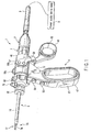
- FIG. 1 schematically shows the entire structure of a handpiece 1 of an ultrasonic therapeutic apparatus which is a surgical operating apparatus according to the first embodiment.
- the ultrasonic therapeutic apparatus of the present embodiment is an ultrasonic coagulation/incision apparatus.
- This ultrasonic coagulation/incision apparatus can perform therapeutic treatment, such as incision, resection or coagulation, of a living body tissue by making use of ultrasonic, and can also perform therapeutic treatment by high-frequency waves.
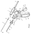
- the handpiece 1 as shown in FIG. 2 , comprises four units, namely, a transducer unit 2, a probe unit (probe section) 3, a handle unit (operation section) 4 and a sheath unit (sheath section) 5. These units are detachably coupled.
- an ultrasonic transducer 6 for generating ultrasonic vibration by a piezoelectric oscillator, which converts an electric current to ultrasonic vibration is built in the transducer unit 2.
- An outside of the ultrasonic transducer 6 is covered with a cylindrical transducer cover 7.
- a cable 9 for supplying an electric current for generating ultrasonic vibration from a power supply device body 8 extends from a rear end of the transducer unit 2.
- a screw hole portion 10a for attaching the probe is formed at a distal end portion of the horn 10.
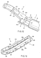
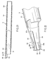
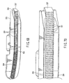
- FIG. 5 shows the external appearance of the entire probe unit 3.
- the probe unit 3 is designed such that the entire length thereof may become an integer number of times of half-wave length of the ultrasonic vibration.
- the probe unit 3 has a distal end portion and a proximal end portion, and includes a metallic rod-shaped vibration transmission member 11 having a long axis.
- a proximal end portion of the vibration transmission member 11 is provided with a screw portion 12 which is to be engaged with the screw hole portion 10a of the horn 10.
- the screw portion 12 is engaged with the screw hole portion 10a of the horn 10 of the transducer unit 2.
- a first high-frequency electric path 13 through which a high-frequency current is transmitted, is formed in the coupled body of the ultrasonic transducer 6 and the probe unit 3.
- a probe distal end portion 3a is provided at a distal end portion of the vibration transmission member 11.
- the probe distal end portion 3a is formed in a substantially J-shaped curved form.
- the probe distal end portion 3a constitutes a first electrode section which is one of bipolar electrodes.
- the cross-sectional area of the probe unit 3 is decreased in the axial direction at several nodes of vibration in the axial direction, so that an amplitude necessary for therapeutic treatment can be obtained at the probe distal end portion 3a.
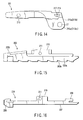
- Rubber rings 3b (see FIG. 7 ), which are formed of elastic material in an annular shape, are attached to several positions of nodes of vibration along the axial direction of the probe unit 3. The rubber rings 3b prevent interference between the probe unit 3 and the sheath unit 5.
- a flange portion 14 is provided at the position of the node of vibration on the most proximal end side in the axial direction of the probe unit 3. As shown in FIG. 6 , engaging recess portions 15 each having a key groove shape are formed on the outer peripheral surface of the flange portion 14 at three positions in the circumferential direction thereof.
- FIG. 8A shows a distal end portion of the sheath unit 5, and FIG. 9A shows a proximal end portion of the sheath unit 5.
- the sheath unit 5 includes a sheath body 16, which is formed of a cylindrical body, and a jaw 17 which is provided at a distal end of the sheath body 16.
- the sheath body 16 includes a metallic sheath 18 which is an outer cylinder, and a metallic driving pipe 19 which is an inner cylinder.
- the driving pipe 19 is axially movably inserted in the sheath 18.
- the outer peripheral surface of the sheath 18 is covered with an outer coating 18a which is formed of an insulating material such as a resin.
- An insulation tube 24, which is formed of an insulating material, is provided on the inner peripheral side of the driving pipe 19.
- a pair of right and left projection portions 25 are provided at a distal end portion of the sheath 18 so as to project in a forward direction of the sheath 18.
- a proximal end portion of the jaw 17 is rotatably attached to the projection portions 25 via a support pin 27.
- the jaw 17 is formed in a substantially J-shaped curved form, which corresponds to the curved shape of the probe distal end portion 3a, in accordance with the curved shape of the probe distal end portion 3a of the probe unit 3.
- the jaw 17 is configured to be rotated about the support pin 27 by the advancing/retreating movement of the driving pipe 19 in the axial direction.
- a therapeutic section 1A of the handpiece 1 is constituted by the jaw 17 and the probe distal end portion 3a.
- the jaw 17 includes a metallic jaw body 201 (see FIG. 14 ) which is an electrically conductive member, and a hold member 202 which is attached to the jaw body 201.
- the hold member 202 is composed of an electrode member 203 (see FIG. 15 ) for high-frequency therapeutic treatment, and an insulation member 204 (see FIG. 16 ) for ultrasonic therapeutic treatment.
- the electrode member 203 constitutes a second electrode section which is the other electrode of the bipolar electrodes.
- a groove portion 205 which is formed in accordance with the curved shape of the probe distal end portion 3a, is formed on the lower surface of the electrode member 203.
- An engaging surface 206 which is to be engaged with the probe distal end portion 3a, is formed by the groove portion 205.
- a groove width W of the groove portion 205 is set in consideration of the diameter dimension of the probe distal end portion 3a. Specifically, the groove width W is set to be greater than the diameter dimension of the probe distal end portion 3a by a predetermined ratio, thereby preventing contact between the engaging surface 206 of the electrode member 203 and the probe distal end portion 3a.
- Inclined surfaces 205a which are configured to gradually increase the groove width toward a lower-side opening surface, as shown in FIG. 18 , are formed on both side wall surfaces of the groove portion 205.
- tooth portions 203b for preventing a slip are formed on both side walls 203a of the groove portion 205 on the lower-side opening surface side.
- the tooth portions 203b form a slip-preventing section for preventing a slip of a clamped object between the probe distal end portion 3a and the jaw 17 when the jaw 17 and probe distal end portion 3a are engaged.
- a wall thickness T of the electrode member 203 is properly determined in consideration of the rigidity and coagulation performance.
- a notch portion 205b is formed at a bottom portion of the groove portion 205.
- the notch portion 205b is formed in accordance with the curved shape of the probe distal end portion 3a.
- a pad member 207 which is formed of an insulating material, for instance, a resin material such as polytetrafluoroethylene, is disposed in the notch portion 205b. As shown in FIG. 18 , the pad member 207 is a probe contact member which is in contact with the probe distal end portion 3a. The probe distal end portion 3a comes in contact with the pad member 207, thus securing a clearance between the second electrode section of the electrode member 203 and the probe distal end portion 3a.
- the jaw 17 has a block-shaped distal end chip 208 at a distal end portion of the engaging surface 206 for engagement with the probe distal end portion 3a.
- the distal end chip 208 is formed of an insulating material, for instance, a resin material such as polytetrafluoroethylene.
- the distal end chip 208 is coupled to the distal end portion of the pad member 207.
- the pad member 207 and the distal end chip 208 are provided as one body.
- the electrode member 203 and insulation member 204 are integrally assembled to form the hold member 202.
- a hook-shaped engaging portion 209 is formed at a rear end portion of the insulation member 204.
- a distal end chip engaging portion 203c which engages the distal end chip 208, is formed at the distal end portion of the electrode member 203.
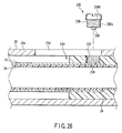
- a projection portion 210 for attachment is provided on that side of the hold member 202, which is opposed to the engaging surface 206 for engagement with the probe distal end portion 3a.
- a screw insertion hole 211 is formed in the projection portion 210.
- a hold member engaging portion 212 which engages the projection portion 210 of the hold member 202, is provided on a distal end side of the jaw body 201.
- the hold member 202 is engaged with the hold member engaging portion 212.
- a screw hole 213 is formed in side wall portions of the hold member engaging portion 212.
- a fixing screw 214 which is engaged in the screw hole 213 of the jaw body 201, is inserted in the screw insertion hole 211 of the hold member 202.
- the fixing screw 214 is fastened in the screw hole 213, and thereby the hold member 202 is attached to the jaw body 201.
- the electrode member 203 of the hold member 202 and the jaw body 201 are electrically connected via the fixing screw 214.
- a proximal end portion of the jaw body 201 has two-forked arm portions 215a and 215b.
- the respective arm portions 215a and 215b have extension portions 215a1 and 215b1, which extend obliquely downward from a position of a center line of the jaw body 201.
- the extension portions 215a1 and 215b1 are rotatably attached by the support pin 27 to the right and left projection portions 25 at the distal end portion of the sheath 18.
- a coupling pin insertion hole 216 is formed in a proximal portion of each of the two arm portions 215a and 215b.
- a coupling pin 217 for coupling the jaw body 201 and the driving pipe 19 is inserted in the coupling pin insertion holes 216.
- the jaw body 201 and the driving pipe 19 are electrically connected via the coupling pin 217.
- the driving force of the driving pipe 19 is transmitted to the jaw 17 via the coupling pin 217 by the advancing/retreating in the axial direction of the driving pipe 19. Accordingly, the jaw 17 is rotated about the support pin 27.
- the jaw 17 is rotated about the support pin 27 and driven (to an open position) in a direction away from the probe distal end portion 3a.
- the driving pipe 19 is pushed forward, the jaw 17 is rotated about the support pin 27 and driven (to a closed position) in a direction toward the probe distal end portion 3a.
- a living body tissue is held between the jaw 17 and the probe distal end portion 3a of the probe unit 3 when the jaw 17 is rotated to the closed position.
- the therapeutic section 1A of the handpiece 1 is constituted by the jaw 17 and the probe distal end portion 3a of the probe unit 3.
- the therapeutic section 1A is configured to selectively perform a plurality of therapeutic functions, for example, two therapeutic functions (a first therapeutic function and a second therapeutic function) in this embodiment.
- the first therapeutic function is set to be a function of simultaneously outputting an ultrasonic therapeutic output and a high-frequency therapeutic output.
- the second therapeutic function is set to be a function of outputting only the high-frequency therapeutic output.
- the first therapeutic function and second therapeutic function of the therapeutic section 1A are not limited to the above-described configuration.
- the first therapeutic function may be set to be a function of outputting an ultrasonic therapeutic output in a maximum output state
- the second therapeutic function may be set to be a function of outputting the ultrasonic therapeutic output in a preset arbitrary output state which is lower than the maximum output state.
- the jaw 17 has, at a distal end portion of the groove portion 205, a distal-end-side groove width varying section 205t1 which has such a tapering shape that the groove width of the groove portion 205 gradually increases toward the distal end.
- the jaw 17 has, at a proximal end portion of the groove portion 205, a proximal-end-side groove width varying section 205t2 which has such a tapering shape that the groove width of the groove portion 205 gradually increases toward the proximal end.
- a positional displacement in assembly between the probe distal end portion 3a and the electrode member 203 of the jaw 17 can be tolerated in a case where the assembly position of the electrode member 203 of the jaw 17 is slightly displaced, relative to the probe distal end portion 3a, in the axial direction of the sheath unit 5 when the probe unit 3 and the sheath unit 5 are assembled.
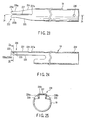
- FIG. 21 shows the driving pipe 19.
- the driving pipe 19 includes a tubular body section 221 and an operating section 222.
- the body section 221 is inserted in the sheath 18 so as to be slidable in the axial direction of the sheath 18.
- the operating section 222 is disposed on the distal end side of the body section 221, and includes a connection section 223 which is connected to the jaw 17.
- the peripheral wall of a tubular distal end portion of the body section 221 includes a crescent-shaped arcuate cross-sectional portion 224, which is formed by leaving a substantially crescent-shaped arcuate cross-sectional portion over a predetermined length in the axial direction, and cutting out the other portion.
- the arcuate cross-sectional portion 224 includes a taper portion 225 with a tapered distal end portion, which is gradually tapered toward the distal end side.
- a U-shaped potion 226 having a U-shaped cross section is formed at a distal end of the taper portion 225.
- the operating section 222 is constituted by the U-shaped portion 226.
- the U-shaped portion 226 has two side surfaces 226a and 226b, which are opposed to each other, and a connecting surface 226c which connects the two side surfaces 226a and 226b.
- the connection section 223 is formed in each of the two side surfaces 226a and 226b of the U-shaped portion 226.
- the operating section 222 has a slit 227 extending in the axial direction of the sheath 18 in a distal end portion of the connecting surface 226c. As shown in FIG. 23 , the slit 227 has a terminal end portion 227a which is located at a position corresponding to a proximal end portion of the taper portion 225.
- the insulation tube 24 includes a projection portion 228 which projects forward of the body section 221 of the driving pipe 19.
- the projection portion 228 extends up to a rear end position of the U-shaped portion 226.
- a proximal end portion of the insulation tube 24 extends to a proximal end side of the sheath body 16.
- the driving pipe 19 and probe unit 3 are electrically insulated by the insulation tube 24.
- FIG. 9 shows a proximal end portion of the sheath body 16.
- the proximal end portion of the sheath 18 includes a flare portion 229 which has a greater inside diameter than the other portion.
- a proximal end portion of the driving pipe 19 extends more rearward than the flare portion 229 of the sheath 18.
- Seal means 230 for effecting sealing between the sheath 18 and the driving pipe 19 is provided between the flare portion 229 and the driving pipe 19.
- the seal means 230 includes two backup rings 231 and 232 and one O ring 233.
- the two backup rings 231 and 232 are disposed between the flare portion 229 and the driving pipe 19 in the state in which the two backup rings 231 and 232 are paired in a back-and-forth direction along the axis of the sheath 18.
- the O ring 233 is provided between the backup rings 231 and 232 so as to be movable in the axial direction of the sheath 18.
- the attachment/detachment mechanism section 31 includes a cylindrical large-diameter handle member 32 which is formed of a resin material, a guide cylindrical body (first tubular member) 33 which is formed of a metallic cylindrical body, and a cylindrical connection tube body (second tubular member) 34 which is formed of a resin material.
- the guide cylindrical body 33 includes a tubular body 33a which is fitted on the flare portion 229 of the proximal end portion of the sheath 18 and extends rearward.
- a distal end portion of the tubular body 33a is provided with a large-diameter 33b which has a greater outside diameter than the other portion thereof.
- the handle member 32 is fitted on the large-diameter portion 33b.
- a connection flange portion 33c, which projects outward, is formed on an outer peripheral surface of a rear end portion of the guide cylindrical body 33.
- an outer peripheral wall portion of the tubular 33a has an elongated slit 234 extending in the axial direction of the sheath 18.
- a distal end portion of the connection tube body 34 is inserted so as to be slidable in the axial direction of the sheath 18.
- a proximal end portion of the driving pipe 19 is fitted and inserted inside the inner peripheral surface of the distal end portion of the connection tube body 34.
- a threaded pin (projection body) 235 is fixed to a proximal end portion of the driving pipe 19.
- the threaded pin 235 includes a male screw member 236.
- a large-diameter portion 236b which has a greater diameter than the male screw portion 236a, is formed on a head portion of the screw member 236.
- the large-diameter portion 236b of the threaded pin 235 is an engaging portion which is engaged in the slit 234 of the guide cylindrical body 33.
- the small-diameter portion 238 is inserted and fitted in a fixing hole 239 which is formed in a proximal end portion of the driving pipe 19.
- the male screw portion 236a of the threaded pin 235 is engaged in and passed through the screw hole portion 237 of the connection tube body 34, and a coupling body 240, in which the driving pipe 19 and the connection tubular body 34 are coupled, is formed.
- the large-diameter portion 236b of the threaded pin 235 is engaged with the slit 234 of the guide cylindrical body 33, and thereby the coupling body 240 is coupled to the guide cylindrical body 33 so as to be movable as one body along the slit 234 in the axial direction of the sheath 18.
- a fixing section 35 of the guide cylindrical body 33 is formed by an engaging section between the handle member 32 and the large-diameter portion 33b of the guide cylindrical body 33. Further, in the handle member 32, an attachment/detachment section 36 for attachment/detachment to/from the handle unit 4 is disposed on the rear side of the fixing section 35.
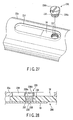
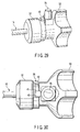
- FIG. 29 to FIG. 32 show the structure of the attachment/detachment part between the handle member 32 and the handle unit 4.
- the attachment/detachment section 36 of the handle member 32 has a guide groove 41 with an inclined surface, and an engaging recess portion 42.
- the guide groove 41 is provided to extend in a circumferential direction on the outer peripheral surface of the proximal end portion of the handle member 32.
- the guide groove 41 has a tapered inclined surface with an outside diameter decreasing toward the rear end portion side of the handle member 32.
- the engaging recess portion 42 is formed at one end portion of the guide groove 41.
- the engaging recess portion 42 is formed of a recess portion having a smaller diameter than the inclined surface of the guide groove 41.
- the engaging recess portion 42 is configured such that the engaging lever 43 (to be described later) on the handle unit 4 side is disengageably engaged in the engaging recess portion 42.
- FIGS. 31 and 32 show the state in which the engaging lever 43 is engaged in the engaging recess portion 42
- FIGS. 29 and 30 show the disengaged state in which the engaging lever 43 is pulled out of the engaging recess portion 42.
- a proximal end portion of the connection tube body 34 has two guide grooves 44 which are used at a time of attachment/detachment to/from the handle unit 4 side.
- the guide grooves 44 are configured such that two engaging pins 45 (to be described later) on the handle unit 4 side are disengageably engaged in the guide grooves 44, respectively.
- An engaging groove 44a which restricts movement of the engaging pin 45 in the axial direction of the sheath body 16, is formed at a terminal end portion of the guide groove 44.
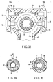
- connection flange portion 33c of the guide cylindrical body 33 has a non-circular engaging portion 46.
- the engaging portion 46 has three cut-out flat-surface portions 46a at a plurality of locations on the circular outer peripheral surface of the connection flange portion 33c, for example, at three locations in this embodiment. Corner portions 46b, each having a greater diameter than the flat-surface portion 46a, are formed at connection parts between the three flat-surface portions 46. Thereby, the engaging portion 46 with a substantially triangular cross section is formed on the connection flange portion 33c. It is not necessary that the non-circular engaging portion 46 have a substantially triangular shape.
- the non-circular engaging portion 46 may have any other non-circular shape, for instance, a polygon such as a rectangle or a pentagon.
- the handle unit 4 mainly includes a stationary handle 47, a hold cylinder 48, a movable handle 49 and a rotational operation knob 50.
- the hold cylinder 48 is provided on the upper part of the stationary handle 47.
- a switch hold section 51 is provided between the stationary handle 47 and the hold cylinder 48.
- the switch hold section 51 includes a switch attachment section 52 which is fixed to a lower end portion of the hold cylinder 48, and a cover member 53 which is fixed to an upper end portion of the stationary handle 47.
- the switch attachment section 52 has a switch attachment surface 52a on a front side thereof, to which a plurality of hand switches, for example, two hand switches (first switch 54 and second switch 55) in the present embodiment, are attached.
- the first switch 54 and second switch 55 are switches for selecting therapeutic functions of the therapeutic section 1A of the handpiece 1.
- the first switch 54 and second switch 55 are arranged in the up-and-down direction.
- the first switch 54 is disposed on an upper side of the switch attachment surface 52a, and is set to be a switch which selects a first therapeutic function that is frequently used among the plural therapeutic functions.
- the second switch 55 is disposed on a lower side of the switch attachment surface 52a, and is set to be a switch which selects another second therapeutic function of the plural therapeutic functions.
- the movable handle 49 has a substantially U-shaped arm section 56 at an upper part thereof.
- the U-shaped arm section 56 includes two arms 56a and 56b.
- the movable handle 49 is assembled to the hold cylinder 48 in the state in which the hold cylinder 48 is inserted between the two arms 56a and 56b.
- Each of the arms 56a and 56b has a support pin 57 and an operation pin 58. As shown in FIG. 36 , a pin receiving hole portion 59 and a window portion 60 are formed in each of both side portions of the hold cylinder 48. The support pin 57 of each arm 56a, 56b is inserted in the pin receiving hole portion 59 of the hold cylinder 48. Thereby, an upper end portion of the movable handle 49 is rotatably supported on the hold cylinder 48 via the support pins 57.
- Ring-shaped finger hook portions 61 and 62 are provided on lower end portions of the stationary handle 47 and movable handle 49, respectively. By hooking the fingers on the finger hook portions 61 and 62 and holding them, the movable handle 49 rotates via the support pins 57 and the movable handle 49 is opened/closed relative to the stationary handle 47.
- the operation pins 58 of the movable handle 49 extend into the hold cylinder 48 through the window portions 60 of the hold cylinder 48.
- An operation force transmission mechanism 63 which transmits an operation force of the movable handle 49 to the driving pipe 19 of the jaw 17, is provided inside the hold cylinder 48.
- the operation force transmission mechanism 63 mainly comprises a metallic cylindrical spring receiving member 64 and a resin-made slider member 65.
- the spring receiving member 64 is disposed coaxially with the center axis of the hold cylinder 48, and extends in the same direction as the direction of insertion of the probe unit 3.
- a coil spring 67, the slider member 65, a stopper 68 and a spring receiver 69 are provided on an outer peripheral surface of the spring receiving member 64.
- a front end portion of the coil spring 67 is fixed to the spring receiver 69.
- the stopper 68 restricts the position of movement of a rear end side of the slider member 65.
- the coil spring 67 is disposed between the spring receiver 69 and the slider member 65 with a fixed amount of mounting force.
- An annular engaging groove 65a is formed in a circumferential direction in an outer peripheral surface of the slider member 65.
- the operation pins 58 of the movable handle 49 are inserted and engaged in the engaging groove 65a. If the movable handle 49 is held and the movable handle 49 is closed relative to the stationary handle 47, the operation pins 58 rotate about the support pins 57 in accordance with the rotational operation of the movable handle 49 at this time.
- the slider member 65 which is in interlock with the rotation of the support pins 57, moves forward in the axial direction.
- the spring receiving member 64 which is coupled to the slider member 65 via the coil spring 67, moves forward/backward together with the slider member 65. As shown in FIG.
- a pair of engaging pins 45 which are used when the sheath unit 5 and the handle unit 4 are attached/detached, are fixed to a distal end portion of the spring receiving member 64. Thereby, the operation force of the movable handle 49 is transmitted to the connection tube body 34 of the sheath unit 5 via the pair of engaging pins 45, and the driving pipe 19 of the jaw 17 moves forward. Thereby, the jaw body 201 of the jaw 17 rotates via the support pin 27.
- the hold member 202 rotates over a certain angle about the pin 214 in accordance with the bending of the probe distal end portion 3a so that force uniformly acts over the entire length of the hold member 202.
- ultrasonic is output and a living body tissue, such as a blood vessel, can be coagulated or cut.
- An annular bearing portion 70 is formed at a front end portion of the hold cylinder 48.
- the bearing portion 70 is metallic, and a cylindrical rotation transmission member 71 is coupled to the bearing portion 70 rotatably about the axis.
- the rotation transmission member 71 includes a projecting portion 72 which projects forward of the bearing portion 70, and a large-diameter portion 73 which extends to the inner side of the hold cylinder 48 from the bearing portion 70.
- the rotational operation knob 50 is fitted and fixed on the projecting portion 72.
- the engaging lever 43 is provided at the front end portion of the rotational operation knob 50.
- An intermediate portion of the engaging lever 43 is rotatably coupled to the projecting portion 72 via a pin 74.
- a proximal end portion of the engaging lever 43 extends to the inside of a lever receiving recess portion 75 which is formed in a front surface of the rotational operation knob 50.
- An operation button 76 for operating the engaging lever 43 in such a direction as to disengage the engaging lever 43 is provided on an outer peripheral surface of the front end portion of the rotational operation knob 50.
- An operation pin 77 which is disposed downward, is provided so as to project from the operation button 76.
- the operation pin 77 extends to the inside of the lever receiving recess portion 75 through a wall hole of the rotational operation knob 50.
- a proximal end portion of the engaging lever 43 is rotatably coupled to a lower end portion of the operation pin 77 via a pin 78.
- a removal prevention ring 80 for the rotational operation knob 50 is provided on a distal end portion of the projecting portion 72.
- a male threaded portion 79 is formed on the distal end portion of the projecting portion 72.
- a female threaded portion 80a which is to be meshed with the male threaded portion 79, is formed on an inner peripheral surface of the removal prevention ring 80. The female threaded portion 80a of the removal prevention ring 80 is meshed and engaged with the male threaded portion 79 of the projecting portion 72, and thereby the rotational operation knob 50 is fixed to the rotation transmission member 71.
- the spring receiver 69 of the spring receiving member 64 is provided with four metallic positioning pins 81 which project radially outward.
- the engaging hole portion 82 extends in the same direction as the direction of insertion of the probe unit 3.
- Engaging means 94 which is disengageably engaged with the connection flange portion 33c of the sheath unit 5, is provided on the inner peripheral surface of the rotation transmission member 71.
- FIGS. 41A and 41B show the engaging means 94.
- the engaging means 94 includes an insertion hole portion 94a in which the connection flange portion 33c is inserted when the sheath unit 5 and handle unit 4 are coupled, and an electrically conductive rubber ring (urging means) 94b which is disposed within the insertion hole portion 94a.
- the shape of the inner peripheral surface of the electrically conductive rubber ring 94b is substantially the same as the shape of the engaging portion 46 of the connection flange portion 33c.
- the inner peripheral surface of the electrically conductive rubber ring 94b has three cut-out flat-surface portions 94b1 at a plurality of locations on the circular outer peripheral surface, for example, at three locations in this embodiment, and three corner portions 94b2 which are located at connection parts between the three flat-surface portions 94b1 and have greater diameters than the flat-surface portions 94b1.
- the electrically conductive rubber ring 94b has a substantially triangular cross-sectional shape.
- the electrically conductive rubber ring 94b is held in a natural, non-compressed position in the positional state in which the inner peripheral surface shape of the electrically conductive rubber ring 94b corresponds to the engaging portion 46 of the connection flange portion 33c, that is, in the state in which the three corner portions 46b of the connection flange portion 33c correspond in position to the three corner portions 94b2 of the electrically conductive rubber ring 94b.
- the handle unit 4 and the sheath unit 5 relative to each other about the center axis of the sheath unit 5, the position of the electrically conductive rubber ring 94b is switched to a pressure contact position, as shown in FIG.
- the electrically rubber ring 94b is held in the natural, non-compressed position, as shown in FIG. 41A .
- the engaging lever 43 on the handle unit 4 side is held in the state in which the engaging lever 43 rests on the inclined surface of the guide groove 41 of the handle member 32 of the sheath unit 5.
- the handle member 32 of the sheath unit 5 is rotated about the axis, relative to the handle unit 4.
- the engaging lever 43 on the handle unit 4 side is inserted and engaged in the engaging recess portion 42 at one end portion of the guide groove 41.
- the electrically conductive rubber ring 94b is switched to the pressure contact position where the electrically conductive rubber ring 94b is put in pressure contact with the three corner portions 46b of the connection flange portion 33c.
- a sheath-unit-side electric path 40 (formed between the guide cylindrical body 33, fixing screw 39, coupling pipe 38, sheath 18, distal end cover 25, support pin 27 and jaw body 28) and a handle-unit-side electric path 95 (formed between an electrical contact member 96, spring receiving member 64, positioning pin 81 and rotation transmission member 71) are electrically connected via the electrically conductive rubber ring 94b.
- a second high-frequency electric path 97 which transmits a high-frequency current, is formed in the coupled body of the sheath unit 5 and handle unit 4.
- the handle unit 4 includes a tubular member 98 which is formed of an insulating material on the inner peripheral surface of the spring receiving member 64.
- the tubular member 98 is fixed on the inner peripheral surface of the spring receiving member 64.
- An inner peripheral surface of the tubular member 98 has three engaging projection portions 99 which correspond to the three engaging recess portions 15 (see FIG. 6 ) of the flange portion 14 of the probe unit 3.
- the three engaging projection portions 99 of the tubular member 98 are disengageably engaged with the three engaging recess portions 15 of the flange portion 14 of the probe unit 3.
- the rotational-directional position between the probe unit 3 and the tubular member 98 of the handle unit 4 is restricted.
- the rotational operation knob 50 is rotated, the coupled body of the probe unit 3 and transducer unit 2 is rotated as one body together with the assembly unit within the hold cylinder 48.
- the engaging section between the flange portion 14 of the probe unit 3 and the tubular member 98 is not limited to the above-described structure.
- the tubular member 98 may be formed to have a D-shaped cross section
- the flange portion 14 of the probe unit 3 may be formed to have a corresponding D-shaped cross section.
- FIGS. 43 to 45 show a cylindrical contact-point unit 66 which is assembled to the hold cylinder 48.
- the contact-point unit 66 includes a cylindrical electrode hold member 83 which is formed of a resin.
- the electrode hold member 83 includes three (first to third) electrode receiving sections 84, 85 and 86 with different outside diameters.
- the first electrode receiving section 84 on the distal end side has a smallest diameter
- the third electrode receiving section 86 on the rear end side has a greatest diameter.
- FIG. 46 shows the first electrode receiving section 84
- FIG. 47 shows the second electrode receiving section 85
- FIG. 48 shows the third electrode receiving section 86.
- the first electrode receiving section 84 has one contact-point member fixing hole 84a, and two through-holes 84b and 84c.
- a center line of the two through-holes 84b and 84c is set to be perpendicular to a center line of the contact-point member fixing hole 84a.
- the second electrode receiving section 85 has one contact-point member fixing hole 85a, and two through-holes 85b and 85c.
- the third electrode receiving section 86 has one contact-point member fixing hole 86a, and two through-holes 86b and 86c.
- the positions of the contact-point member fixing hole 84a of the first electrode receiving section 84, the contact-point member fixing hole 85a of the second electrode receiving section 85 and the contact-point member fixing hole 86a of the third electrode receiving section 86 are displaced in the circumferential direction of the electrode hold member 83.
- FIG. 49 and FIG. 50 show electrode members 87A, 87B and 87C which are assembled to the first to third electrode receiving sections 84, 85 and 86. These electrode members 87A, 87B and 87C are formed in the same shape. In the description below, only the electrode member 87A, which is assembled to the first electrode receiving section 84, is described. The common parts of the electrode members 87B and 87C of the other second and third electrode receiving sections 85 and 86 are denoted by like reference numerals, and a description thereof is omitted.
- the electrode member 87A includes one straight stationary portion 87a and two bend portions 87b and 87C.
- One bend portion 87b is disposed at one end of the straight stationary portion 87a
- the other bend portion 87c is disposed at the other end of the straight stationary portion 87a.
- the electrode member 87A is formed and bent in a substantially U shape.
- a hole 88 and an L-shaped wiring connection portion 89 are provided at a central position of the stationary portion 87a.
- Inwardly curved waist portions 90 are formed at central positions of the two bend portions 87b and 87c.
- a fixing pin 91 is inserted in the hole 88 of the stationary portion 87a of the electrode member 87A and in the contact-point member fixing hole 84a of the first electrode receiving section 84.
- the electrode member 87A is fixed to the first electrode receiving section 84 by the fixing pin 91.
- the waist portion 90 of one bend portion 87b of the electrode member 87A is disposed in one through-hole 84b of the first electrode receiving section 84
- the waist portion 90 of the other bend portion 87c of the electrode member 87A is disposed in the other through-hole 84c.
- the electrode member 87B is assembled to the second electrode receiving section 85 and the electrode member 87C is assembled to the third electrode receiving section 86.
- a large-diameter fixing flange portion 83a is formed at a rear end portion of the electrode hold member 83 of the contact-point unit 66.
- Engaging projection portions 83b are provided to project from the outer peripheral surface of the fixing flange portion 83a at a plurality of locations, for example, at three locations in this embodiment.
- Engaging recess portions 48a are formed in an inner peripheral surface of the rear end portion of the hold cylinder 48 at positions corresponding to the three engaging projection portions 83b of the stationary flange portion 83a.
- the electrode hold member 83 In the case where the electrode hold member 83 is assembled in the hold cylinder 48, the three engaging projection portions 83b of the stationary flange portion 83a are inserted, engaged and fixed in the engaging recess portions 48a of the hold cylinder 48. Thereby, the rotation of the electrode hold member 83 about the axis thereof, relative to the hold cylinder 48, is restricted.
- the electrode hold member 83 is fixed to the hold cylinder 48 by a fixing screw 48c in the state in which the fixing flange portion 83a of the electrode hold member 83 abuts upon the stepped portion 43b. Thereby, the axial movement of the electrode hold member 83, relative to the hold cylinder 48, is restricted.
- End portions of three wiring lines 93a to 93c, which are assembled in the switch hold section 51, are connected to the wiring connection portions 89 of the three electrode members 87A, 87B and 87C that are assembled to the contact-point unit 66.
- the contact-point unit 66 is provided with a substantially C-shaped electric contact-point member 96 which is formed of a metallic plate spring.
- the electric contact-point member 96 is connected to the outer-peripheral surface of the proximal end portion of the spring receiving member 64.
- the handle-unit-side electric path 95 is composed of the electrical contact member 96, spring receiving member 64, positioning pin 81 and rotation transmission member 71.
- a front end portion of the transducer unit 2 is detachably coupled to the contact-point unit 66.
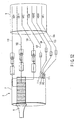
- two wiring lines 101 and 102 for the ultrasonic transducer, two wiring lines 103 and 104 for high-frequency power and three wiring lines 105, 106 and 107, which are connected to a wiring circuit board within the switch hold section 51, are assembled in the single cable 9 at the rear end of the transducer unit 2.
- Distal end portions of the two wiring lines 101 and 102 for the ultrasonic transducer are connected to the ultrasonic transducer 6.
- a distal end portion of one wiring line 103 for high-frequency power is connected to the ultrasonic transducer 6.
- First to fourth electrically conductive plates 111 to 114 for electric connection are provided at the rear end of the transducer unit 2.
- a distal end portion of the other wiring line 104 for high-frequency power is connected to the first conductive plate 111.
- the three wiring lines 105, 106 and 107 are connected to the second to fourth conductive plates 112 to 114.
- FIG. 4 shows the internal structure of a front end portion of the transducer unit 2.
- a connection cylindrical portion 121 is formed at the distal end portion of the transducer cover 7.
- a C-ring 122 having a partly cut-out annular plate shape is mounted on the outer peripheral surface of the connection cylindrical body 121.
- Three (first to third) cylindrical portions 123 to 125 with different outside diameters are projectingly provided on the inside of the connection cylindrical portion 121.
- the first cylindrical portion 123 has a smallest outside diameter and has a greatest length of projection from the distal end of the connection cylindrical body 121.
- the second cylindrical portion 124 has an outside diameter, which is greater than the outside diameter of the first cylindrical portion 123, and has a length of projection from the distal end of the connection cylindrical body 121, which is less than the length of projection of the first cylindrical portion 123.
- the third cylindrical portion 125 has a greatest outside diameter and has a length of projection from the distal end of the connection cylindrical body 121, which is less than the length of projection of the second cylindrical portion 124.
- a first cylindrical contact-point member 131 is mounted on the outer peripheral surface of the first cylindrical portion 123.
- a second cylindrical contact-point member 132 is mounted on the outer peripheral surface of the second cylindrical portion 124, and a third cylindrical contact-point member 133 is mounted on the outer peripheral surface of the third cylindrical portion 125.
- the second conductive plate 112 is connected to the first contact-point member 131, the third conductive plate 113 is connected to the second contact-point member 132, and the fourth conductive plate 114 is connected to the third contact-point member 133.
- a fourth contact-point member 134 is mounted on the inner peripheral surface of the first cylindrical body 123.
- the fourth contact-point member 134 is connected to the first conductive plate 111.
- the contact-point unit 66 of the handle unit 4 and the front end portion of the transducer unit 2 are connected.
- the electrode member 87A of the contact-point unit 66 and the first contact-point member 131 of the transducer unit 2 are connected.
- the electrode member 87B of the contact-point unit 66 and the second contact-point member 132 of the transducer unit 2 are connected, the electrode member 87C of the contact-point unit 66 and the third contact-point member 133 of the transducer unit 2 are connected, and the C-shaped electric contact-point member 96 of the contact-point unit 66 and the fourth contact-point member 134 of the transducer unit 2 are connected.
- the handpiece 1 of the ultrasonic therapeutic apparatus of the present embodiment comprises four units, namely, the transducer unit 2, probe unit 3, handle unit 4 and sheath unit 5, which are detachable.
- the transducer unit 2 and the probe unit 3 are coupled.
- the first high-frequency electric path 13 which transmits a high-frequency current to the coupled body of the transducer unit 2 and probe unit 3, is formed.
- the handle unit 4 and the sheath unit 5 are coupled.
- the connection tube body 34 is inserted in the rotation transmission member 71 of the handle unit 4 in the state in which the handle member 32 of the sheath unit 5 is held.
- the engaging lever 43 on the handle unit 4 side is held in the state in which the engaging lever 43 rests on the inclined surface of the guide groove 41 of the handle member 32 of the sheath unit 5, as shown in FIG. 29 and FIG. 30 .
- FIG. 29 and FIG. 30 As shown in FIG.
- the electrically conductive rubber ring 94b is held in the positional state in which the inner peripheral surface shape of the electrically conductive rubber ring 94b corresponds to the engaging portion 46 of the connection flange portion 33c, that is, in the state in which the three corner portions 46b of the connection flange portion 33c correspond in position to the three corner portions 94b2 of the electrically conductive rubber ring 94b. Accordingly, the connection flange portion 33c of the sheath unit 5 is inserted straight into the electrically conductive rubber ring 94b. At the time of this insertion operation, as shown in FIG. 41A , the conductive rubber ring 94b is held in the natural, non-compressed position. In this state, the sheath-unit-side electric path 40 and the handle-unit-side electric path 95 are not electrically connected.
- the handle member 32 of the sheath unit 5 is rotated about the axis thereof, relative to the handle unit 4.
- the engaging lever 43 on the handle unit 4 side is inserted and engaged in the engaging recess portion 42 at one end portion of the guide groove 41.
- the electrically conductive rubber ring 94b is switched to the pressure contact position where the electrically conductive rubber ring 94b is put in pressure contact with the three corner portions 46b of the connection flange portion 33c.
- the sheath-unit-side electric path 40 and the handle-unit-side electric path 95 are electrically connected via the electrically conductive rubber ring 94b.
- the second high-frequency electric path 97 which transmits a high-frequency current, is formed in the coupled body of the sheath unit 5 and handle unit 4.
- the coupled body of the sheath unit 5 and handle unit 4 and the coupled body of the ultrasonic transducer 6 and probe unit 3 are assembled as one body.
- the contact-point unit 66 of the handle unit 4 is connected to the front end portion of the transducer unit 2.
- the electrode member 87A of the contact-point unit 66 and the first contact-point member 131 of the transducer unit 2 are connected.
- the electrode member 87B of the contact-point unit 66 and the second contact-point member 132 of the transducer unit 2 are connected, the electrode member 87C of the contact-point unit 66 and the third contact-point member 133 of the transducer unit 2 are connected, and the C-shaped electric contact-point member 96 of the contact-point unit 66 and the fourth contact-point member 134 of the transducer unit 2 are connected.
- the second high-frequency electric path 97 of the coupled body of the sheath unit 5 and handle unit 4 is connected to the wiring line 104 for high-frequency power within the cable 9.
- the three wiring lines 105, 106 and 107 within the cable 9 are connected to the wiring circuit board within the switch hold section 51. This state is the completion state of the assembly of the handpiece 1.
- the movable handle 49 When the handpiece 1 is used, the movable handle 49 is opened/closed relative to the stationary handle 47.
- the driving pipe 19 is axially moved in interlock with the operation of the movable handle 49, and the jaw 17 is opened/closed, relative to the probe distal end portion 3a of the probe unit 3, in interlock with the advancing/retreating movement of the driving pipe 19 in its axial direction.
- the driving pipe 19 When the movable handle 49 is closed relative to the stationary handle 47, the driving pipe 19 is pushed forward in interlock with the operation of the movable handle 49.
- the jaw 17 is rotated and driven (to a closed position) in a direction toward the probe distal end portion 3a of the probe unit 3 in interlock with the pushing operation of the driving pipe 19. By the rotation of the jaw 17 to its closed position, a living body tissue is held between the jaw 17 and the probe distal end portion 3a of the probe unit 3.
- one of the switch button 54 for coagulation and the switch button 55 for incision which are provided on the stationary handle 47, is selectively pressed.
- the switch button 54 for coagulation is pressed, power is supplied to the first high-frequency electric path 13 for supplying a high-frequency current to the probe distal end portion 3a of the probe unit 3 and to the second high-frequency electric path 97 for supplying a high-frequency current to the jaw body 28 of the sheath unit 5.
- the two bipolar electrodes for high-frequency therapeutic treatment are constituted by the probe distal end portion 3a of the probe unit 3 and the jaw body 28 of the sheath unit 5.
- bipolar high-frequency therapeutic treatment can be performed for the living body tissue between the jaw 17 and the probe distal end portion 3a of the probe unit 3.
- the driving pipe 19 is pulled to the proximal side in interlock with the opening operation of the removable handle 49.
- the jaw 17 is driven (to an open position) in a direction away from the probe distal end portion 3a of the probe unit 3 in interlock with the pulling operation of the driving pipe 19.
- the handle member 32 and guide cylindrical body 33 of the sheath unit 5 rotate together with the rotational operation knob 50. Furthermore, the sheath 18 rotates together with the guide cylindrical body 33, and the rotation of the guide cylindrical body 33 is transmitted to the connection tube body 34 and driving pipe 19 via the threaded pin 235. Thus, the jaw 17 and probe distal end portion 3a of the therapeutic section 1A are rotated about the axis at the same time together with the rotational operation knob 50.
- the jaw 17 has the distal end chip 208 at a distal end portion of the engaging surface 206 for engagement with the probe distal end portion 3a.
- the distal end chip 208 When the jaw 17 and probe distal end portion 3a are engaged, a positional displacement relative to the probe distal end portion 3a is tolerated by the distal end chip 208.
- the distal end of the probe distal end portion 3a can exactly be put in contact with the distal end chip 208 which is the insulator.
- a fixed amount of clearance can be kept between the electrode member 203 of the jaw 17 and the probe distal end portion 3a after assembly, and contact between the electrode member 203 of the jaw 17 and the probe distal end portion 3a can be prevented. Since the bipolar high-frequency therapeutic function can be secured, it is not necessary to precisely manage a fabrication error of parts of the apparatus and an error in assembly, and the manufacturing cost can be reduced.
- the entire distal end portion of the engaging surface 206 for engagement with the probe distal end portion 3a is formed by the distal end chip 208.
- the jaw 17 has, at the distal end portion of the groove portion 205, the distal-end-side groove width varying section 205t1 which has such a tapering shape that the groove width of the groove portion 205 gradually increases toward the distal end.
- the jaw 17 has, at the proximal end portion of the groove portion 205, the proximal-end-side groove width varying section 205t2 which has such a tapering shape that the groove width of the groove portion 205 gradually increases toward the proximal end.
- the jaw 17 has the tooth portions 203b for preventing a slip, which are formed on both side walls 203a of the groove portion 205 of the electrode member 203.
- the tooth portions 203b can be made to bite into a clamped object between the probe distal end portion 3a and the jaw 17. Thereby, a slip of the clamped object between the probe distal end portion 3a and the jaw 17 can be prevented.
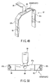
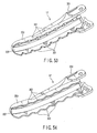
- FIG. 53 shows a further example of the ultrasonic therapeutic apparatus.
- the structure of the jaw 17 in the first embodiment is altered as follows.
- a plurality of substantially trapezoidal teeth 301 are juxtaposed on both side walls 203a of the electrode member 203.
- the substantially trapezoidal teeth 301 are provided on the hold surface that comes in contact with a living body tissue.
- the trapezoidal teeth 301 can be made to bite into a clamped object between the probe distal end portion 3a and the jaw 17. Thereby, a slip of the clamped object between the probe distal end portion 3a and the jaw 17 can be prevented.
- the trapezoidal teeth 301 have obtuse-angled corner portions, and have no acute-angled edge portions.
- the electrode member 203 of the jaw 17 has acute-angled edge portions
- corner portions of the trapezoidal teeth 301 have obtuse-angled shapes, no spark occurs between the jaw 17 and the probe distal end portion 3a, and burning of the living body tissue can be prevented.
- FIG. 54 shows a second embodiment of the ultrasonic therapeutic apparatus of the present invention.
- the structure of the jaw 17 in the first embodiment is altered as follows.
- a plurality of large-wavy-shaped teeth 302 are juxtaposed on both side walls 203a of the electrode member 203.
- the large-wavy-shaped teeth 302 are provided on the hold surface that comes in contact with a living body tissue.
- the wavy-shaped teeth 302 can be made to bite into a clamped object between the probe distal end portion 3a and the jaw 17. Thereby, a slip of the clamped object between the probe distal end portion 3a and the jaw 17 can be prevented.
- the large-wavy-shaped teeth 302 have no corner portions and have gently curved shapes, no acute-angled edge portions are formed.
- no spark occurs between the jaw 17 and the probe distal end portion 3a, and burning of the living body tissue can be prevented.
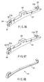
- FIGS. 57 to 61 show a third embodiment of the present invention.
- the structure of the jaw 17 in the first embodiment is altered as follows.
- FIG. 57 shows the external appearance of the jaw 17 of this embodiment.
- the pad member 207 which is formed of an insulator, has an outer contact surface that comes in contact with the probe distal end portion 3a, and this contact surface is provided with a wear-prevention portion 311 for preventing wear of the pad member 207.
- FIG. 60 shows the external appearance of the pad member 207.
- a mounting groove 312 for mounting the wear-prevention portion 311 is provided in the outer contact surface of the pad member 207, which comes in contact with the probe distal end portion 3a. Further, a front end fixing portion 313a for fixing a front end of the wear-prevention portion 311 is formed at a front end portion of the pad member 207, and a rear end fixing portion 313b for fixing a rear end of the wear-prevention portion 311 is formed at a rear end portion of the pad member 207.
- the wear-prevention portion 311 in this embodiment includes, for example, an elongated plate-shaped metallic pad 314 which is formed of a metallic material.
- FIG. 61 shows the metallic pad 314.
- a front end bend portion 315 which is attached to the front end fixing portion 313a of the pad member 207, is formed at a front end portion of the metallic pad 314.
- a rear end bend portion 316 which is attached to the rear end fixing portion 313b of the pad member 207, is formed at a rear end portion of the metallic pad 314.
- the front end bend portion 315 of the metallic pad 314 is attached to the front end fixing portion 313a of the pad member 207, and the rear end bend portion 316 of the metallic pad 314 is attached to the rear end fixing portion 313b of the pad member 207.
- the metallic pad 314 is inserted in the mounting groove 312 of the pad member 207. In this state, the metallic pad 314 is fixed to the pad member 207.
- the pad member 207 is interposed between the metallic pad 314 and the electrode member 203. Thereby, the metallic pad 314 and the electrode member 203 are electrically insulated.
- the outer contact surface of the pad member 207 which comes in contact with the probe distal end portion 3a, has the metallic pad 314 for preventing wear of the pad member 207.
- the pad member 207 of the jaw 17 is prevented from coming in direct contact with the probe distal end portion 3a. Therefore, the pad member 207 of the jaw 17 can be prevented from being worn due to contact with the probe distal end portion 3a.
- the wear-resistance properties of the part of the jaw 17, which comes in contact with the probe distal end portion 3a can be improved.
- the wear-prevention portion 311 is not necessarily limited to the metallic pad 314 of the metallic material.
- the wear-prevention portion 311 may be formed of a ceramic material, a hard resin material, etc.
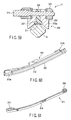
- FIGS. 62 to 68 show a fourth embodiment of the present invention.
- the structure of the jaw 17 in the third embodiment of the invention is altered as follows.
- a metallic pad 314 is assembled to an insulation member 204 shown in FIG. 63 by bending a metallic plate 321 shown in FIG. 64 .
- a recess-shaped front end fixing portion 313a for fixing a front end of the metallic pad 314 is formed at a front end portion of the insulation member 204
- a recess-shaped rear end fixing portion 313b for fixing a rear end of the metallic pad 314 is formed at a rear end portion of the insulation member 204.
- FIG. 64 shows a metallic plate 321 prior to bending of the metallic pad 314 of the jaw 17.
- a front end bend portion 322, which is bent substantially at right angles, is formed at a front end portion of the metallic plate 321.
- a small bend portion 323, which is bent at right angles, is further formed at a distal end portion of the front end bend portion 322.
- a substantially L-shaped bend portion 324 is formed of the front end bend portion 322 and the small bend portion 323.
- a rear end bend portion 325 which is bent substantially at right angles, is formed at a rear end portion of the metallic plate 321.
- FIG. 65 illustrates a first step of assembling the metallic pad 314 to the insulation member 204 of the jaw 17.
- the L-shaped bend portion 324 of the metallic plate 321 is engaged and fixed in the front end fixing portion 313a of the insulation member 204.
- FIG. 66 illustrates a second step of assembling the metallic pad 314 to the insulation member 204 of the jaw 17.
- the metallic plate 321 shown in FIG. 65 is further bent in the vicinity of the L-shaped bend portion 324 in accordance with the shape of the front end fixing portion 313a of the insulation member 204.
- the rear end bend portion 325 of the metallic plate 321 is moved to the position of the rear end fixing portion 313b of the insulation member 204.
- FIG. 67 illustrates a third step of assembling the metallic pad 314 to the insulation member 204 of the jaw 17.
- the rear end bend portion 325 of the metallic plate 321 shown in FIG. 66 is further bent in accordance with the shape of the rear end fixing portion 313b of the insulation member 204.
- the rear end bend portion 325 of the metallic plate 321 is engaged and fixed in the rear end fixing portion 313b of the insulation member 204.
- FIG. 68 shows the shape of the metallic pad 314 of the jaw 17 after the bending process.
- the metallic pad 314 is assembled to the insulation member 204 shown in FIG. 63 by bending the metallic plate 321 shown in FIG. 64 . Therefore, the metallic pad 314 can be assembled in the insulation member 204 by a simple work, and the jaw 17 can be manufactured at low cost.
- FIG. 69 and FIG. 70 show a further example.
- the structure of the jaw 17 is altered as follows.
- planar hold surfaces 304 with no teeth are formed on both side walls 203a of the electrode member 203. Further, a plurality of teeth 331 are juxtaposed on the outer contact surface of the pad member 207 of the insulator, which comes in contact with the probe distal end portion 3a.
- the planar hold surfaces 304 on both side walls 203a of the electrode member 203 are put in contact with a living body tissue.
- no spark occurs between the jaw 17 and the probe distal end portion 3a, and burning of the living body tissue can be prevented.
- the plural teeth 331 are juxtaposed on the outer contact surface of the pad member 207, which comes in contact with the probe distal end portion 3a.
- the teeth 331 of the pad member 207 can be made to bite into a clamped object between the probe distal end portion 3a and the jaw 17. Thereby, a slip of the clamped object between the probe distal end portion 3a and the jaw 17 can be prevented.
- FIG. 71 shows another example.
- the structure of the jaw 17 in the first embodiment is altered as follows. Specifically, in this example, the distal end chip 208 at the distal end portion of the jaw 17 is dispensed with.
- the distal-end-side groove width varying section 205t1 which is provided at the distal end portion of the groove portion 205 of the electrode member 203 of the jaw 17, is extended to the distal end of the electrode member 203.
- the electrode member 203 can be extended up to the foremost distal end of the jaw 17. Therefore, when therapeutic treatment by the handpiece 1 is performed, the high-frequency therapeutic treatment can be performed up to the foremost position of the jaw 17, and thus the range of high-frequency therapeutic treatment by the jaw 17 can be increased.
Landscapes
- Health & Medical Sciences (AREA)
- Surgery (AREA)
- Life Sciences & Earth Sciences (AREA)
- Engineering & Computer Science (AREA)
- Veterinary Medicine (AREA)
- Molecular Biology (AREA)
- Nuclear Medicine, Radiotherapy & Molecular Imaging (AREA)
- Public Health (AREA)
- Biomedical Technology (AREA)
- Heart & Thoracic Surgery (AREA)
- Medical Informatics (AREA)
- General Health & Medical Sciences (AREA)
- Animal Behavior & Ethology (AREA)
- Otolaryngology (AREA)
- Plasma & Fusion (AREA)
- Physics & Mathematics (AREA)
- Dentistry (AREA)
- Mechanical Engineering (AREA)
- Pathology (AREA)
- Surgical Instruments (AREA)
Claims (6)
- Chirurgische Operationsvorrichtung mit:einer Hülle (18), die einen distalen Endbereich und einen proximalen Endbereich aufweist;einem schaftförmigen Sondenkörper (11), der durch die Hülle (18) eingeführt wird und einen distalen Endbereich und einen proximalen Endbereich aufweist, und in welchem eine Ultraschallschwingung übertragen zu werden vermag;einem Sondendistalendbereich (3a), der am distalen Endbereich des Sondenkörpers (11) vorgesehen ist und einen gekrümmten Bereich aufweist, welcher relativ zu einer axialen Richtung des Sondenkörpers (11) gekrümmt und dazu ausgebildet ist, als eine von bipolaren Elektroden zu fungieren; undeiner Klemmbacke (17), die drehbar am distalen Endbereich der Hülle (18) gehalten ist und eine Eingriffsfläche (206) bildet, die dazu ausgebildet ist, mit dem Sondendistalendbereich (3a) in Eingriff zu kommen, wobei die Klemmbacke (17) aufweist: einen Elektrodenbereich (203a), der dazu ausgebildet ist, als die andere der bipolaren Elektroden zu fungieren, und einen Nutbereich (205) aufweist, der die Eingriffsfläche (206) bildet und eine Form hat, die dem gekrümmten Bereich des Sondendistalendbereichs (3a) entspricht; und einen isolierenden Kontaktbereich (207), der an einem Bodenbereich des Nutbereichs (205) angeordnet und dazu ausgebildet ist, mit dem Sondendistalendbereich (3a) in Kontakt zu kommen, um einen Abstand zwischen dem Elektrodenbereich (203a) und dem Sondendistalendbereich (3a) sicherzustellen,wobei die Klemmbacke (17) einen isolierenden Distalendchip (208) aufweist, der die Gesamtheit eines Distalendbereichs der Eingriffsfläche (206) bildet,dadurch gekennzeichnet, dass
der Elektrodenbereich (203a) an einem distalen Endbereich des Elektrodenbereichs (203a) einen distalendseitigen Nutbreiten-Variationsbereich (205t1) aufweist, der eine derartige konisch zulaufende Form hat, dass eine Nutbreite des Nutbereichs (205) in Richtung einer distalen Endseite allmählich zunimmt, und/oder
der Elektrodenbereich (203a) an einem proximalen Endbereich des Elektrodenbereichs (203a) einen proximalendseitigen Nutbreiten-Variationsbereich (205t2) aufweist, der eine derartige konisch zulaufende Form hat, dass eine Nutbreite des Nutbereichs (205) in Richtung einer proximalen Endseite allmählich zunimmt. - Vorrichtung nach Anspruch 1, dadurch gekennzeichnet, dass
die Klemmbacke (17) einen Schlupfverhinderungsbereich (203b) aufweist, der dazu ausgebildet ist, den Schlupf eines Objekts zu verhindern, das zwischen dem Sondendistalendbereich (3a) und der Klemmbacke (17) eingeklemmt ist, wenn die Klemmbacke (17) und der Sondendistalendbereich (3a) das Objekt einklemmen. - Vorrichtung nach Anspruch 1, dadurch gekennzeichnet, dass
die Klemmbacke (17) auf der Eingriffsfläche (206) einen Verschleißverhinderungsbereich (311) zum Verhindern eines Verschleißes des Kontaktbereichs (207) aufweist. - Vorrichtung nach Anspruch 3, dadurch gekennzeichnet, dass
der Verschleißverhinderungsbereich (311) ein Metallkontaktfeld (314) aufweist, das durch den isolierenden Kontaktbereich (207) gegen den Elektrodenbereich (203a) isoliert ist. - Vorrichtung nach Anspruch 2, dadurch gekennzeichnet, dass
der Schlupfverhinderungsbereich (203b) eine wellig geformte gezahnte Fläche (301, 302) ist, die auf dem Elektrodenbereich (203a) ausgebildet ist. - Vorrichtung nach Anspruch 2, dadurch gekennzeichnet, dass
der Schlupfverhinderungsbereich (203b) eine wellig geformte gezahnte Fläche (331) ist, die auf dem Kontaktbereich (207) ausgebildet ist.
Applications Claiming Priority (1)
| Application Number | Priority Date | Filing Date | Title |
|---|---|---|---|
| US12/316,658 US8147488B2 (en) | 2007-12-28 | 2007-12-28 | Surgical operating apparatus |
Publications (2)
| Publication Number | Publication Date |
|---|---|
| EP2074959A1 EP2074959A1 (de) | 2009-07-01 |
| EP2074959B1 true EP2074959B1 (de) | 2012-12-05 |
Family
ID=40673838
Family Applications (1)
| Application Number | Title | Priority Date | Filing Date |
|---|---|---|---|
| EP08016451A Active EP2074959B1 (de) | 2007-12-28 | 2008-09-18 | Chirurgische Operationsvorrichtung |
Country Status (5)
| Country | Link |
|---|---|
| US (1) | US8147488B2 (de) |
| EP (1) | EP2074959B1 (de) |
| JP (1) | JP5307530B2 (de) |
| KR (1) | KR101171412B1 (de) |
| CN (1) | CN101467917B (de) |
Cited By (1)
| Publication number | Priority date | Publication date | Assignee | Title |
|---|---|---|---|---|
| USD691265S1 (en) | 2011-08-23 | 2013-10-08 | Covidien Ag | Control assembly for portable surgical device |
Families Citing this family (220)
| Publication number | Priority date | Publication date | Assignee | Title |
|---|---|---|---|---|
| US11229472B2 (en) | 2001-06-12 | 2022-01-25 | Cilag Gmbh International | Modular battery powered handheld surgical instrument with multiple magnetic position sensors |
| US8182501B2 (en) | 2004-02-27 | 2012-05-22 | Ethicon Endo-Surgery, Inc. | Ultrasonic surgical shears and method for sealing a blood vessel using same |
| EP3162309B1 (de) | 2004-10-08 | 2022-10-26 | Ethicon LLC | Chirurgisches ultraschallinstrument |
| US20070191713A1 (en) | 2005-10-14 | 2007-08-16 | Eichmann Stephen E | Ultrasonic device for cutting and coagulating |
| US7621930B2 (en) | 2006-01-20 | 2009-11-24 | Ethicon Endo-Surgery, Inc. | Ultrasound medical instrument having a medical ultrasonic blade |
| US8057498B2 (en) | 2007-11-30 | 2011-11-15 | Ethicon Endo-Surgery, Inc. | Ultrasonic surgical instrument blades |
| US20080234709A1 (en) | 2007-03-22 | 2008-09-25 | Houser Kevin L | Ultrasonic surgical instrument and cartilage and bone shaping blades therefor |
| US8226675B2 (en) | 2007-03-22 | 2012-07-24 | Ethicon Endo-Surgery, Inc. | Surgical instruments |
| US8911460B2 (en) | 2007-03-22 | 2014-12-16 | Ethicon Endo-Surgery, Inc. | Ultrasonic surgical instruments |
| US8142461B2 (en) | 2007-03-22 | 2012-03-27 | Ethicon Endo-Surgery, Inc. | Surgical instruments |
| US8882791B2 (en) | 2007-07-27 | 2014-11-11 | Ethicon Endo-Surgery, Inc. | Ultrasonic surgical instruments |
| US8257377B2 (en) | 2007-07-27 | 2012-09-04 | Ethicon Endo-Surgery, Inc. | Multiple end effectors ultrasonic surgical instruments |
| US8523889B2 (en) | 2007-07-27 | 2013-09-03 | Ethicon Endo-Surgery, Inc. | Ultrasonic end effectors with increased active length |
| US8808319B2 (en) | 2007-07-27 | 2014-08-19 | Ethicon Endo-Surgery, Inc. | Surgical instruments |
| US8348967B2 (en) | 2007-07-27 | 2013-01-08 | Ethicon Endo-Surgery, Inc. | Ultrasonic surgical instruments |
| US8430898B2 (en) | 2007-07-31 | 2013-04-30 | Ethicon Endo-Surgery, Inc. | Ultrasonic surgical instruments |
| US9044261B2 (en) | 2007-07-31 | 2015-06-02 | Ethicon Endo-Surgery, Inc. | Temperature controlled ultrasonic surgical instruments |
| US8512365B2 (en) | 2007-07-31 | 2013-08-20 | Ethicon Endo-Surgery, Inc. | Surgical instruments |
| US8252012B2 (en) | 2007-07-31 | 2012-08-28 | Ethicon Endo-Surgery, Inc. | Ultrasonic surgical instrument with modulator |
| AU2008308606B2 (en) | 2007-10-05 | 2014-12-18 | Ethicon Endo-Surgery, Inc. | Ergonomic surgical instruments |
| US10010339B2 (en) | 2007-11-30 | 2018-07-03 | Ethicon Llc | Ultrasonic surgical blades |
| US7901423B2 (en) | 2007-11-30 | 2011-03-08 | Ethicon Endo-Surgery, Inc. | Folded ultrasonic end effectors with increased active length |
| US8058771B2 (en) | 2008-08-06 | 2011-11-15 | Ethicon Endo-Surgery, Inc. | Ultrasonic device for cutting and coagulating with stepped output |
| US9089360B2 (en) | 2008-08-06 | 2015-07-28 | Ethicon Endo-Surgery, Inc. | Devices and techniques for cutting and coagulating tissue |
| US9700339B2 (en) | 2009-05-20 | 2017-07-11 | Ethicon Endo-Surgery, Inc. | Coupling arrangements and methods for attaching tools to ultrasonic surgical instruments |
| US8334635B2 (en) | 2009-06-24 | 2012-12-18 | Ethicon Endo-Surgery, Inc. | Transducer arrangements for ultrasonic surgical instruments |
| US8663220B2 (en) | 2009-07-15 | 2014-03-04 | Ethicon Endo-Surgery, Inc. | Ultrasonic surgical instruments |
| US8461744B2 (en) | 2009-07-15 | 2013-06-11 | Ethicon Endo-Surgery, Inc. | Rotating transducer mount for ultrasonic surgical instruments |
| PL3263054T3 (pl) * | 2009-07-15 | 2019-08-30 | Ethicon Llc | Ultradźwiękowe narzędzie chirurgiczne mające zacisk |
| US9017326B2 (en) | 2009-07-15 | 2015-04-28 | Ethicon Endo-Surgery, Inc. | Impedance monitoring apparatus, system, and method for ultrasonic surgical instruments |
| USRE47996E1 (en) | 2009-10-09 | 2020-05-19 | Ethicon Llc | Surgical generator for ultrasonic and electrosurgical devices |
| US9168054B2 (en) | 2009-10-09 | 2015-10-27 | Ethicon Endo-Surgery, Inc. | Surgical generator for ultrasonic and electrosurgical devices |
| US10441345B2 (en) | 2009-10-09 | 2019-10-15 | Ethicon Llc | Surgical generator for ultrasonic and electrosurgical devices |
| US9039695B2 (en) | 2009-10-09 | 2015-05-26 | Ethicon Endo-Surgery, Inc. | Surgical generator for ultrasonic and electrosurgical devices |
| US10172669B2 (en) | 2009-10-09 | 2019-01-08 | Ethicon Llc | Surgical instrument comprising an energy trigger lockout |
| US11090104B2 (en) | 2009-10-09 | 2021-08-17 | Cilag Gmbh International | Surgical generator for ultrasonic and electrosurgical devices |
| JP4898980B2 (ja) * | 2010-01-21 | 2012-03-21 | オリンパスメディカルシステムズ株式会社 | 外科処置装置 |
| US8579928B2 (en) | 2010-02-11 | 2013-11-12 | Ethicon Endo-Surgery, Inc. | Outer sheath and blade arrangements for ultrasonic surgical instruments |
| US8419759B2 (en) | 2010-02-11 | 2013-04-16 | Ethicon Endo-Surgery, Inc. | Ultrasonic surgical instrument with comb-like tissue trimming device |
| US8531064B2 (en) | 2010-02-11 | 2013-09-10 | Ethicon Endo-Surgery, Inc. | Ultrasonically powered surgical instruments with rotating cutting implement |
| US8469981B2 (en) | 2010-02-11 | 2013-06-25 | Ethicon Endo-Surgery, Inc. | Rotatable cutting implement arrangements for ultrasonic surgical instruments |
| US9259234B2 (en) | 2010-02-11 | 2016-02-16 | Ethicon Endo-Surgery, Llc | Ultrasonic surgical instruments with rotatable blade and hollow sheath arrangements |
| US8382782B2 (en) | 2010-02-11 | 2013-02-26 | Ethicon Endo-Surgery, Inc. | Ultrasonic surgical instruments with partially rotating blade and fixed pad arrangement |
| US8323302B2 (en) | 2010-02-11 | 2012-12-04 | Ethicon Endo-Surgery, Inc. | Methods of using ultrasonically powered surgical instruments with rotatable cutting implements |
| US8961547B2 (en) | 2010-02-11 | 2015-02-24 | Ethicon Endo-Surgery, Inc. | Ultrasonic surgical instruments with moving cutting implement |
| US8486096B2 (en) | 2010-02-11 | 2013-07-16 | Ethicon Endo-Surgery, Inc. | Dual purpose surgical instrument for cutting and coagulating tissue |
| US8951272B2 (en) | 2010-02-11 | 2015-02-10 | Ethicon Endo-Surgery, Inc. | Seal arrangements for ultrasonically powered surgical instruments |
| GB2480498A (en) | 2010-05-21 | 2011-11-23 | Ethicon Endo Surgery Inc | Medical device comprising RF circuitry |
| US8795327B2 (en) | 2010-07-22 | 2014-08-05 | Ethicon Endo-Surgery, Inc. | Electrosurgical instrument with separate closure and cutting members |
| US9192431B2 (en) | 2010-07-23 | 2015-11-24 | Ethicon Endo-Surgery, Inc. | Electrosurgical cutting and sealing instrument |
| US8979890B2 (en) | 2010-10-01 | 2015-03-17 | Ethicon Endo-Surgery, Inc. | Surgical instrument with jaw member |
| US8888809B2 (en) | 2010-10-01 | 2014-11-18 | Ethicon Endo-Surgery, Inc. | Surgical instrument with jaw member |
| US20120116381A1 (en) | 2010-11-05 | 2012-05-10 | Houser Kevin L | Surgical instrument with charging station and wireless communication |
| US9089338B2 (en) | 2010-11-05 | 2015-07-28 | Ethicon Endo-Surgery, Inc. | Medical device packaging with window for insertion of reusable component |
| US10085792B2 (en) | 2010-11-05 | 2018-10-02 | Ethicon Llc | Surgical instrument with motorized attachment feature |
| US10660695B2 (en) | 2010-11-05 | 2020-05-26 | Ethicon Llc | Sterile medical instrument charging device |
| US9510895B2 (en) | 2010-11-05 | 2016-12-06 | Ethicon Endo-Surgery, Llc | Surgical instrument with modular shaft and end effector |
| US9161803B2 (en) | 2010-11-05 | 2015-10-20 | Ethicon Endo-Surgery, Inc. | Motor driven electrosurgical device with mechanical and electrical feedback |
| US9000720B2 (en) | 2010-11-05 | 2015-04-07 | Ethicon Endo-Surgery, Inc. | Medical device packaging with charging interface |
| US9011471B2 (en) | 2010-11-05 | 2015-04-21 | Ethicon Endo-Surgery, Inc. | Surgical instrument with pivoting coupling to modular shaft and end effector |
| US9597143B2 (en) | 2010-11-05 | 2017-03-21 | Ethicon Endo-Surgery, Llc | Sterile medical instrument charging device |
| US9381058B2 (en) | 2010-11-05 | 2016-07-05 | Ethicon Endo-Surgery, Llc | Recharge system for medical devices |
| US9782214B2 (en) | 2010-11-05 | 2017-10-10 | Ethicon Llc | Surgical instrument with sensor and powered control |
| US9526921B2 (en) | 2010-11-05 | 2016-12-27 | Ethicon Endo-Surgery, Llc | User feedback through end effector of surgical instrument |
| US9072523B2 (en) | 2010-11-05 | 2015-07-07 | Ethicon Endo-Surgery, Inc. | Medical device with feature for sterile acceptance of non-sterile reusable component |
| US9421062B2 (en) | 2010-11-05 | 2016-08-23 | Ethicon Endo-Surgery, Llc | Surgical instrument shaft with resiliently biased coupling to handpiece |
| US9017851B2 (en) | 2010-11-05 | 2015-04-28 | Ethicon Endo-Surgery, Inc. | Sterile housing for non-sterile medical device component |
| US9017849B2 (en) | 2010-11-05 | 2015-04-28 | Ethicon Endo-Surgery, Inc. | Power source management for medical device |
| US9649150B2 (en) | 2010-11-05 | 2017-05-16 | Ethicon Endo-Surgery, Llc | Selective activation of electronic components in medical device |
| US10881448B2 (en) | 2010-11-05 | 2021-01-05 | Ethicon Llc | Cam driven coupling between ultrasonic transducer and waveguide in surgical instrument |
| US20120116265A1 (en) | 2010-11-05 | 2012-05-10 | Houser Kevin L | Surgical instrument with charging devices |
| US10959769B2 (en) | 2010-11-05 | 2021-03-30 | Ethicon Llc | Surgical instrument with slip ring assembly to power ultrasonic transducer |
| US9375255B2 (en) | 2010-11-05 | 2016-06-28 | Ethicon Endo-Surgery, Llc | Surgical instrument handpiece with resiliently biased coupling to modular shaft and end effector |
| CA2816875A1 (en) * | 2010-11-05 | 2012-05-10 | Ethicon Endo-Surgery, Inc. | Surgical instrument with modular end effector |
| US9782215B2 (en) | 2010-11-05 | 2017-10-10 | Ethicon Endo-Surgery, Llc | Surgical instrument with ultrasonic transducer having integral switches |
| US9039720B2 (en) | 2010-11-05 | 2015-05-26 | Ethicon Endo-Surgery, Inc. | Surgical instrument with ratcheting rotatable shaft |
| US9247986B2 (en) | 2010-11-05 | 2016-02-02 | Ethicon Endo-Surgery, Llc | Surgical instrument with ultrasonic transducer having integral switches |
| JP5259883B2 (ja) | 2011-02-10 | 2013-08-07 | オリンパスメディカルシステムズ株式会社 | 高周波手術装置及び手術装置 |
| US8968293B2 (en) | 2011-04-12 | 2015-03-03 | Covidien Lp | Systems and methods for calibrating power measurements in an electrosurgical generator |
| KR101298237B1 (ko) * | 2011-06-09 | 2013-08-22 | 국립암센터 | 수술 장치 |
| US9259265B2 (en) | 2011-07-22 | 2016-02-16 | Ethicon Endo-Surgery, Llc | Surgical instruments for tensioning tissue |
| US9421060B2 (en) | 2011-10-24 | 2016-08-23 | Ethicon Endo-Surgery, Llc | Litz wire battery powered device |
| USD687549S1 (en) | 2011-10-24 | 2013-08-06 | Ethicon Endo-Surgery, Inc. | Surgical instrument |
| JP6165780B2 (ja) | 2012-02-10 | 2017-07-19 | エシコン・エンド−サージェリィ・インコーポレイテッドEthicon Endo−Surgery,Inc. | ロボット制御式の手術器具 |
| US10045792B2 (en) * | 2012-02-16 | 2018-08-14 | Song Yee Kim | Tool for surgical operation using ultrasonic waves |
| US9226766B2 (en) | 2012-04-09 | 2016-01-05 | Ethicon Endo-Surgery, Inc. | Serial communication protocol for medical device |
| US9237921B2 (en) | 2012-04-09 | 2016-01-19 | Ethicon Endo-Surgery, Inc. | Devices and techniques for cutting and coagulating tissue |
| US9724118B2 (en) | 2012-04-09 | 2017-08-08 | Ethicon Endo-Surgery, Llc | Techniques for cutting and coagulating tissue for ultrasonic surgical instruments |
| US9241731B2 (en) | 2012-04-09 | 2016-01-26 | Ethicon Endo-Surgery, Inc. | Rotatable electrical connection for ultrasonic surgical instruments |
| US9439668B2 (en) | 2012-04-09 | 2016-09-13 | Ethicon Endo-Surgery, Llc | Switch arrangements for ultrasonic surgical instruments |
| US20140005705A1 (en) | 2012-06-29 | 2014-01-02 | Ethicon Endo-Surgery, Inc. | Surgical instruments with articulating shafts |
| US20140005702A1 (en) | 2012-06-29 | 2014-01-02 | Ethicon Endo-Surgery, Inc. | Ultrasonic surgical instruments with distally positioned transducers |
| US9283045B2 (en) | 2012-06-29 | 2016-03-15 | Ethicon Endo-Surgery, Llc | Surgical instruments with fluid management system |
| US9820768B2 (en) | 2012-06-29 | 2017-11-21 | Ethicon Llc | Ultrasonic surgical instruments with control mechanisms |
| US9408622B2 (en) | 2012-06-29 | 2016-08-09 | Ethicon Endo-Surgery, Llc | Surgical instruments with articulating shafts |
| US9326788B2 (en) | 2012-06-29 | 2016-05-03 | Ethicon Endo-Surgery, Llc | Lockout mechanism for use with robotic electrosurgical device |
| US9351754B2 (en) | 2012-06-29 | 2016-05-31 | Ethicon Endo-Surgery, Llc | Ultrasonic surgical instruments with distally positioned jaw assemblies |
| US9226767B2 (en) | 2012-06-29 | 2016-01-05 | Ethicon Endo-Surgery, Inc. | Closed feedback control for electrosurgical device |
| US9393037B2 (en) | 2012-06-29 | 2016-07-19 | Ethicon Endo-Surgery, Llc | Surgical instruments with articulating shafts |
| US9198714B2 (en) | 2012-06-29 | 2015-12-01 | Ethicon Endo-Surgery, Inc. | Haptic feedback devices for surgical robot |
| WO2014052181A1 (en) | 2012-09-28 | 2014-04-03 | Ethicon Endo-Surgery, Inc. | Multi-function bi-polar forceps |
| US9095367B2 (en) | 2012-10-22 | 2015-08-04 | Ethicon Endo-Surgery, Inc. | Flexible harmonic waveguides/blades for surgical instruments |
| US10201365B2 (en) | 2012-10-22 | 2019-02-12 | Ethicon Llc | Surgeon feedback sensing and display methods |
| US20140135804A1 (en) | 2012-11-15 | 2014-05-15 | Ethicon Endo-Surgery, Inc. | Ultrasonic and electrosurgical devices |
| US10226273B2 (en) | 2013-03-14 | 2019-03-12 | Ethicon Llc | Mechanical fasteners for use with surgical energy devices |
| US9241728B2 (en) | 2013-03-15 | 2016-01-26 | Ethicon Endo-Surgery, Inc. | Surgical instrument with multiple clamping mechanisms |
| JP5866486B2 (ja) | 2013-06-07 | 2016-02-17 | オリンパス株式会社 | 把持処置装置 |
| JP5797355B2 (ja) * | 2013-06-07 | 2015-10-21 | オリンパス株式会社 | 超音波プローブ及び超音波処置装置 |
| US9814514B2 (en) | 2013-09-13 | 2017-11-14 | Ethicon Llc | Electrosurgical (RF) medical instruments for cutting and coagulating tissue |
| EP3064161A4 (de) * | 2013-11-01 | 2017-11-08 | Olympus Corporation | Ultraschallsonde und ultraschallbehandlungsvorrichtung |
| US9265926B2 (en) | 2013-11-08 | 2016-02-23 | Ethicon Endo-Surgery, Llc | Electrosurgical devices |
| GB2521229A (en) | 2013-12-16 | 2015-06-17 | Ethicon Endo Surgery Inc | Medical device |
| GB2521228A (en) | 2013-12-16 | 2015-06-17 | Ethicon Endo Surgery Inc | Medical device |
| US9795436B2 (en) | 2014-01-07 | 2017-10-24 | Ethicon Llc | Harvesting energy from a surgical generator |
| PL2907463T3 (pl) | 2014-02-12 | 2016-08-31 | Erbe Elektromedizin | Instrument chirurgiczny z nośnikiem elektrody |
| WO2015137139A1 (ja) * | 2014-03-14 | 2015-09-17 | オリンパス株式会社 | 把持ユニット及びバイポーラ処置具 |
| US9554854B2 (en) | 2014-03-18 | 2017-01-31 | Ethicon Endo-Surgery, Llc | Detecting short circuits in electrosurgical medical devices |
| US10092310B2 (en) | 2014-03-27 | 2018-10-09 | Ethicon Llc | Electrosurgical devices |
| US10463421B2 (en) | 2014-03-27 | 2019-11-05 | Ethicon Llc | Two stage trigger, clamp and cut bipolar vessel sealer |
| US9737355B2 (en) | 2014-03-31 | 2017-08-22 | Ethicon Llc | Controlling impedance rise in electrosurgical medical devices |
| US9913680B2 (en) | 2014-04-15 | 2018-03-13 | Ethicon Llc | Software algorithms for electrosurgical instruments |
| US9439718B2 (en) | 2014-04-18 | 2016-09-13 | Peter D. Poulsen | Reciprocating cooling member for an energized surgical instrument |
| US9700333B2 (en) | 2014-06-30 | 2017-07-11 | Ethicon Llc | Surgical instrument with variable tissue compression |
| US10285724B2 (en) | 2014-07-31 | 2019-05-14 | Ethicon Llc | Actuation mechanisms and load adjustment assemblies for surgical instruments |
| EP3189803A4 (de) * | 2014-09-05 | 2018-04-04 | Olympus Corporation | Behandlungswerkzeug, sondeneinheit für distale seite und sondeneinheit für basisendseite |
| US10136938B2 (en) | 2014-10-29 | 2018-11-27 | Ethicon Llc | Electrosurgical instrument with sensor |
| US10639092B2 (en) | 2014-12-08 | 2020-05-05 | Ethicon Llc | Electrode configurations for surgical instruments |
| US10076379B2 (en) | 2014-12-15 | 2018-09-18 | Ethicon Llc | Electrosurgical instrument with removable components for cleaning access |
| US10159524B2 (en) | 2014-12-22 | 2018-12-25 | Ethicon Llc | High power battery powered RF amplifier topology |
| US10245095B2 (en) | 2015-02-06 | 2019-04-02 | Ethicon Llc | Electrosurgical instrument with rotation and articulation mechanisms |
| KR101712486B1 (ko) * | 2015-03-04 | 2017-03-07 | 이메드 주식회사 | 고주파 응고 기능을 갖는 초음파 수술장치 |
| US10321950B2 (en) | 2015-03-17 | 2019-06-18 | Ethicon Llc | Managing tissue treatment |
| US10342602B2 (en) | 2015-03-17 | 2019-07-09 | Ethicon Llc | Managing tissue treatment |
| US10595929B2 (en) | 2015-03-24 | 2020-03-24 | Ethicon Llc | Surgical instruments with firing system overload protection mechanisms |
| US10314638B2 (en) | 2015-04-07 | 2019-06-11 | Ethicon Llc | Articulating radio frequency (RF) tissue seal with articulating state sensing |
| US10034684B2 (en) | 2015-06-15 | 2018-07-31 | Ethicon Llc | Apparatus and method for dissecting and coagulating tissue |
| US11020140B2 (en) | 2015-06-17 | 2021-06-01 | Cilag Gmbh International | Ultrasonic surgical blade for use with ultrasonic surgical instruments |
| US10898256B2 (en) | 2015-06-30 | 2021-01-26 | Ethicon Llc | Surgical system with user adaptable techniques based on tissue impedance |
| US11051873B2 (en) | 2015-06-30 | 2021-07-06 | Cilag Gmbh International | Surgical system with user adaptable techniques employing multiple energy modalities based on tissue parameters |
| US11129669B2 (en) | 2015-06-30 | 2021-09-28 | Cilag Gmbh International | Surgical system with user adaptable techniques based on tissue type |
| US10034704B2 (en) | 2015-06-30 | 2018-07-31 | Ethicon Llc | Surgical instrument with user adaptable algorithms |
| US10357303B2 (en) | 2015-06-30 | 2019-07-23 | Ethicon Llc | Translatable outer tube for sealing using shielded lap chole dissector |
| US10765470B2 (en) | 2015-06-30 | 2020-09-08 | Ethicon Llc | Surgical system with user adaptable techniques employing simultaneous energy modalities based on tissue parameters |
| US10154852B2 (en) | 2015-07-01 | 2018-12-18 | Ethicon Llc | Ultrasonic surgical blade with improved cutting and coagulation features |
| EP3332719A4 (de) * | 2015-08-04 | 2019-04-03 | Olympus Corporation | Zangenartiges behandlungswerkzeug |
| WO2017022287A1 (ja) * | 2015-08-05 | 2017-02-09 | オリンパス株式会社 | 処置具 |
| WO2017027853A1 (en) * | 2015-08-12 | 2017-02-16 | Reach Surgical, Inc. | Curved ultrasonic surgical blade |
| US10456157B2 (en) | 2015-08-26 | 2019-10-29 | Ethicon Llc | Ultrasonic surgical instrument clamp arm with snap-on clamp pad |
| JP6197148B2 (ja) * | 2015-09-17 | 2017-09-13 | オリンパス株式会社 | 把持処置具 |
| US10687884B2 (en) | 2015-09-30 | 2020-06-23 | Ethicon Llc | Circuits for supplying isolated direct current (DC) voltage to surgical instruments |
| US10595930B2 (en) | 2015-10-16 | 2020-03-24 | Ethicon Llc | Electrode wiping surgical device |
| US10959771B2 (en) | 2015-10-16 | 2021-03-30 | Ethicon Llc | Suction and irrigation sealing grasper |
| US20170164972A1 (en) * | 2015-12-10 | 2017-06-15 | Ethicon Endo-Surgery, Llc | End effector for instrument with ultrasonic and electrosurgical features |
| US10959806B2 (en) | 2015-12-30 | 2021-03-30 | Ethicon Llc | Energized medical device with reusable handle |
| US10179022B2 (en) | 2015-12-30 | 2019-01-15 | Ethicon Llc | Jaw position impedance limiter for electrosurgical instrument |
| US10575892B2 (en) | 2015-12-31 | 2020-03-03 | Ethicon Llc | Adapter for electrical surgical instruments |
| US10716615B2 (en) | 2016-01-15 | 2020-07-21 | Ethicon Llc | Modular battery powered handheld surgical instrument with curved end effectors having asymmetric engagement between jaw and blade |
| US12193698B2 (en) | 2016-01-15 | 2025-01-14 | Cilag Gmbh International | Method for self-diagnosing operation of a control switch in a surgical instrument system |
| US11058448B2 (en) | 2016-01-15 | 2021-07-13 | Cilag Gmbh International | Modular battery powered handheld surgical instrument with multistage generator circuits |
| US11229471B2 (en) | 2016-01-15 | 2022-01-25 | Cilag Gmbh International | Modular battery powered handheld surgical instrument with selective application of energy based on tissue characterization |
| US11129670B2 (en) | 2016-01-15 | 2021-09-28 | Cilag Gmbh International | Modular battery powered handheld surgical instrument with selective application of energy based on button displacement, intensity, or local tissue characterization |
| US10555769B2 (en) | 2016-02-22 | 2020-02-11 | Ethicon Llc | Flexible circuits for electrosurgical instrument |
| US10856934B2 (en) | 2016-04-29 | 2020-12-08 | Ethicon Llc | Electrosurgical instrument with electrically conductive gap setting and tissue engaging members |
| US10987156B2 (en) | 2016-04-29 | 2021-04-27 | Ethicon Llc | Electrosurgical instrument with electrically conductive gap setting member and electrically insulative tissue engaging members |
| US10485607B2 (en) | 2016-04-29 | 2019-11-26 | Ethicon Llc | Jaw structure with distal closure for electrosurgical instruments |
| US10702329B2 (en) | 2016-04-29 | 2020-07-07 | Ethicon Llc | Jaw structure with distal post for electrosurgical instruments |
| US10646269B2 (en) | 2016-04-29 | 2020-05-12 | Ethicon Llc | Non-linear jaw gap for electrosurgical instruments |
| US10456193B2 (en) | 2016-05-03 | 2019-10-29 | Ethicon Llc | Medical device with a bilateral jaw configuration for nerve stimulation |
| US10245064B2 (en) | 2016-07-12 | 2019-04-02 | Ethicon Llc | Ultrasonic surgical instrument with piezoelectric central lumen transducer |
| US10893883B2 (en) | 2016-07-13 | 2021-01-19 | Ethicon Llc | Ultrasonic assembly for use with ultrasonic surgical instruments |
| WO2018011920A1 (ja) * | 2016-07-13 | 2018-01-18 | オリンパス株式会社 | 把持処置具 |
| CN109475363B (zh) * | 2016-07-13 | 2021-06-18 | 奥林巴斯株式会社 | 把持处置器具和制造方法 |
| US10842522B2 (en) | 2016-07-15 | 2020-11-24 | Ethicon Llc | Ultrasonic surgical instruments having offset blades |
| US10376305B2 (en) | 2016-08-05 | 2019-08-13 | Ethicon Llc | Methods and systems for advanced harmonic energy |
| US10285723B2 (en) | 2016-08-09 | 2019-05-14 | Ethicon Llc | Ultrasonic surgical blade with improved heel portion |
| USD847990S1 (en) | 2016-08-16 | 2019-05-07 | Ethicon Llc | Surgical instrument |
| US10736649B2 (en) | 2016-08-25 | 2020-08-11 | Ethicon Llc | Electrical and thermal connections for ultrasonic transducer |
| US10952759B2 (en) | 2016-08-25 | 2021-03-23 | Ethicon Llc | Tissue loading of a surgical instrument |
| US10751117B2 (en) | 2016-09-23 | 2020-08-25 | Ethicon Llc | Electrosurgical instrument with fluid diverter |
| US10603064B2 (en) | 2016-11-28 | 2020-03-31 | Ethicon Llc | Ultrasonic transducer |
| US11266430B2 (en) | 2016-11-29 | 2022-03-08 | Cilag Gmbh International | End effector control and calibration |
| US11033325B2 (en) | 2017-02-16 | 2021-06-15 | Cilag Gmbh International | Electrosurgical instrument with telescoping suction port and debris cleaner |
| US10799284B2 (en) | 2017-03-15 | 2020-10-13 | Ethicon Llc | Electrosurgical instrument with textured jaws |
| US11497546B2 (en) | 2017-03-31 | 2022-11-15 | Cilag Gmbh International | Area ratios of patterned coatings on RF electrodes to reduce sticking |
| US11129661B2 (en) | 2017-05-22 | 2021-09-28 | Cilag Gmbh International | Combination ultrasonic and electrosurgical system having EEPROM and ASIC components |
| US10603117B2 (en) | 2017-06-28 | 2020-03-31 | Ethicon Llc | Articulation state detection mechanisms |
| US10820920B2 (en) | 2017-07-05 | 2020-11-03 | Ethicon Llc | Reusable ultrasonic medical devices and methods of their use |
| US11484358B2 (en) | 2017-09-29 | 2022-11-01 | Cilag Gmbh International | Flexible electrosurgical instrument |
| US11033323B2 (en) | 2017-09-29 | 2021-06-15 | Cilag Gmbh International | Systems and methods for managing fluid and suction in electrosurgical systems |
| US11490951B2 (en) | 2017-09-29 | 2022-11-08 | Cilag Gmbh International | Saline contact with electrodes |
| US11723716B2 (en) | 2019-12-30 | 2023-08-15 | Cilag Gmbh International | Electrosurgical instrument with variable control mechanisms |
| US12064109B2 (en) | 2019-12-30 | 2024-08-20 | Cilag Gmbh International | Surgical instrument comprising a feedback control circuit |
| US12262937B2 (en) | 2019-12-30 | 2025-04-01 | Cilag Gmbh International | User interface for surgical instrument with combination energy modality end-effector |
| US12114912B2 (en) | 2019-12-30 | 2024-10-15 | Cilag Gmbh International | Non-biased deflectable electrode to minimize contact between ultrasonic blade and electrode |
| US12053224B2 (en) | 2019-12-30 | 2024-08-06 | Cilag Gmbh International | Variation in electrode parameters and deflectable electrode to modify energy density and tissue interaction |
| US12343063B2 (en) | 2019-12-30 | 2025-07-01 | Cilag Gmbh International | Multi-layer clamp arm pad for enhanced versatility and performance of a surgical device |
| US12349961B2 (en) | 2019-12-30 | 2025-07-08 | Cilag Gmbh International | Electrosurgical instrument with electrodes operable in bipolar and monopolar modes |
| US11779329B2 (en) | 2019-12-30 | 2023-10-10 | Cilag Gmbh International | Surgical instrument comprising a flex circuit including a sensor system |
| US11986234B2 (en) | 2019-12-30 | 2024-05-21 | Cilag Gmbh International | Surgical system communication pathways |
| US11707318B2 (en) | 2019-12-30 | 2023-07-25 | Cilag Gmbh International | Surgical instrument with jaw alignment features |
| US12023086B2 (en) | 2019-12-30 | 2024-07-02 | Cilag Gmbh International | Electrosurgical instrument for delivering blended energy modalities to tissue |
| US20210196361A1 (en) | 2019-12-30 | 2021-07-01 | Ethicon Llc | Electrosurgical instrument with monopolar and bipolar energy capabilities |
| US11660089B2 (en) | 2019-12-30 | 2023-05-30 | Cilag Gmbh International | Surgical instrument comprising a sensing system |
| US11911063B2 (en) | 2019-12-30 | 2024-02-27 | Cilag Gmbh International | Techniques for detecting ultrasonic blade to electrode contact and reducing power to ultrasonic blade |
| US11950797B2 (en) | 2019-12-30 | 2024-04-09 | Cilag Gmbh International | Deflectable electrode with higher distal bias relative to proximal bias |
| US11812957B2 (en) | 2019-12-30 | 2023-11-14 | Cilag Gmbh International | Surgical instrument comprising a signal interference resolution system |
| US11696776B2 (en) | 2019-12-30 | 2023-07-11 | Cilag Gmbh International | Articulatable surgical instrument |
| US11786291B2 (en) | 2019-12-30 | 2023-10-17 | Cilag Gmbh International | Deflectable support of RF energy electrode with respect to opposing ultrasonic blade |
| US12336747B2 (en) | 2019-12-30 | 2025-06-24 | Cilag Gmbh International | Method of operating a combination ultrasonic / bipolar RF surgical device with a combination energy modality end-effector |
| US11937863B2 (en) | 2019-12-30 | 2024-03-26 | Cilag Gmbh International | Deflectable electrode with variable compression bias along the length of the deflectable electrode |
| US11452525B2 (en) | 2019-12-30 | 2022-09-27 | Cilag Gmbh International | Surgical instrument comprising an adjustment system |
| US11986201B2 (en) | 2019-12-30 | 2024-05-21 | Cilag Gmbh International | Method for operating a surgical instrument |
| US11944366B2 (en) | 2019-12-30 | 2024-04-02 | Cilag Gmbh International | Asymmetric segmented ultrasonic support pad for cooperative engagement with a movable RF electrode |
| US12082808B2 (en) | 2019-12-30 | 2024-09-10 | Cilag Gmbh International | Surgical instrument comprising a control system responsive to software configurations |
| US12076006B2 (en) | 2019-12-30 | 2024-09-03 | Cilag Gmbh International | Surgical instrument comprising an orientation detection system |
| US11779387B2 (en) | 2019-12-30 | 2023-10-10 | Cilag Gmbh International | Clamp arm jaw to minimize tissue sticking and improve tissue control |
| US12471982B2 (en) | 2020-12-02 | 2025-11-18 | Cilag Gmbh International | Method for tissue treatment by surgical instrument |
| US11957342B2 (en) | 2021-11-01 | 2024-04-16 | Cilag Gmbh International | Devices, systems, and methods for detecting tissue and foreign objects during a surgical operation |
| US12508021B2 (en) | 2021-11-01 | 2025-12-30 | Cilag Gmbh International | Devices, systems, and methods for detecting tissue and foreign objects during a surgical operation |
| WO2026023042A1 (ja) * | 2024-07-25 | 2026-01-29 | オリンパスメディカルシステムズ株式会社 | 超音波処置具 |
Family Cites Families (12)
| Publication number | Priority date | Publication date | Assignee | Title |
|---|---|---|---|---|
| AU663543B2 (en) | 1992-02-07 | 1995-10-12 | Sherwood Services Ag | Ultrasonic surgical apparatus |
| AU672227B2 (en) | 1992-11-30 | 1996-09-26 | Sherwood Services Ag | An ultrasonic surgical handpiece and an energy initiator to maintain the vibration and linear dynamics |
| JP3704399B2 (ja) * | 1996-06-21 | 2005-10-12 | オリンパス株式会社 | 超音波処置具 |
| US6887252B1 (en) | 1996-06-21 | 2005-05-03 | Olympus Corporation | Ultrasonic treatment appliance |
| US6736813B2 (en) * | 1998-01-23 | 2004-05-18 | Olympus Optical Co., Ltd. | High-frequency treatment tool |
| JP3610306B2 (ja) * | 2000-07-05 | 2005-01-12 | オリンパス株式会社 | 高周波処置具 |
| JP4460787B2 (ja) * | 2001-02-13 | 2010-05-12 | オリンパス株式会社 | 超音波処置装置 |
| US20040097911A1 (en) | 2001-02-13 | 2004-05-20 | Olympus Optical Co., Ltd. | Ultrasonic operating apparartus and tool for changing tip thereof |
| US6743228B2 (en) | 2001-09-12 | 2004-06-01 | Manoa Medical, Inc. | Devices and methods for tissue severing and removal |
| JP4398391B2 (ja) | 2005-02-21 | 2010-01-13 | オリンパスメディカルシステムズ株式会社 | 超音波処置装置 |
| JP4402629B2 (ja) * | 2005-08-19 | 2010-01-20 | オリンパスメディカルシステムズ株式会社 | 超音波凝固切開装置 |
| US7645278B2 (en) | 2006-02-22 | 2010-01-12 | Olympus Corporation | Coagulating cutter |
-
2007
- 2007-12-28 US US12/316,658 patent/US8147488B2/en active Active
-
2008
- 2008-09-18 EP EP08016451A patent/EP2074959B1/de active Active
- 2008-12-26 KR KR1020080135010A patent/KR101171412B1/ko not_active Expired - Fee Related
- 2008-12-26 CN CN2008101892138A patent/CN101467917B/zh not_active Expired - Fee Related
- 2008-12-26 JP JP2008333832A patent/JP5307530B2/ja not_active Expired - Fee Related
Cited By (4)
| Publication number | Priority date | Publication date | Assignee | Title |
|---|---|---|---|---|
| USD691265S1 (en) | 2011-08-23 | 2013-10-08 | Covidien Ag | Control assembly for portable surgical device |
| USD700699S1 (en) | 2011-08-23 | 2014-03-04 | Covidien Ag | Handle for portable surgical device |
| USD700966S1 (en) | 2011-08-23 | 2014-03-11 | Covidien Ag | Portable surgical device |
| USD700967S1 (en) | 2011-08-23 | 2014-03-11 | Covidien Ag | Handle for portable surgical device |
Also Published As
| Publication number | Publication date |
|---|---|
| KR101171412B1 (ko) | 2012-08-06 |
| JP5307530B2 (ja) | 2013-10-02 |
| EP2074959A1 (de) | 2009-07-01 |
| JP2009160404A (ja) | 2009-07-23 |
| US20090216228A1 (en) | 2009-08-27 |
| US8147488B2 (en) | 2012-04-03 |
| KR20090073046A (ko) | 2009-07-02 |
| CN101467917B (zh) | 2011-01-12 |
| CN101467917A (zh) | 2009-07-01 |
Similar Documents
| Publication | Publication Date | Title |
|---|---|---|
| EP2074959B1 (de) | Chirurgische Operationsvorrichtung | |
| EP2042112A2 (de) | Chirurgische Operationsvorrichtung | |
| EP2067444A2 (de) | Chirurgische Operationsvorrichtung | |
| US20090088743A1 (en) | Surgical operating apparatus | |
| EP1943969B1 (de) | Ultraschalloperationsvorrichtung | |
| US8048074B2 (en) | Surgical operating apparatus | |
| EP3131474B1 (de) | Chirurgische vorrichtung mit temperatursteuerung | |
| US20100331742A1 (en) | Surgical operating apparatus | |
| EP1943970B1 (de) | Ultraschalloperationsvorrichtung | |
| EP2106757B1 (de) | Chirurgische Operationsvorrichtung | |
| EP2042113A1 (de) | Chirurgische Operationsvorrichtung | |
| US8236017B2 (en) | Ultrasonic therapeutic apparatus |
Legal Events
| Date | Code | Title | Description |
|---|---|---|---|
| PUAI | Public reference made under article 153(3) epc to a published international application that has entered the european phase |
Free format text: ORIGINAL CODE: 0009012 |
|
| 17P | Request for examination filed |
Effective date: 20080918 |
|
| AK | Designated contracting states |
Kind code of ref document: A1 Designated state(s): AT BE BG CH CY CZ DE DK EE ES FI FR GB GR HR HU IE IS IT LI LT LU LV MC MT NL NO PL PT RO SE SI SK TR |
|
| AX | Request for extension of the european patent |
Extension state: AL BA MK RS |
|
| 17Q | First examination report despatched |
Effective date: 20090903 |
|
| AKX | Designation fees paid |
Designated state(s): DE FR GB |
|
| RIC1 | Information provided on ipc code assigned before grant |
Ipc: A61B 17/29 20060101ALN20120405BHEP Ipc: A61B 18/14 20060101AFI20120405BHEP Ipc: A61B 17/32 20060101ALI20120405BHEP |
|
| GRAP | Despatch of communication of intention to grant a patent |
Free format text: ORIGINAL CODE: EPIDOSNIGR1 |
|
| GRAS | Grant fee paid |
Free format text: ORIGINAL CODE: EPIDOSNIGR3 |
|
| GRAA | (expected) grant |
Free format text: ORIGINAL CODE: 0009210 |
|
| AK | Designated contracting states |
Kind code of ref document: B1 Designated state(s): DE FR GB |
|
| REG | Reference to a national code |
Ref country code: GB Ref legal event code: FG4D |
|
| REG | Reference to a national code |
Ref country code: DE Ref legal event code: R096 Ref document number: 602008020544 Country of ref document: DE Effective date: 20130131 |
|
| PLBE | No opposition filed within time limit |
Free format text: ORIGINAL CODE: 0009261 |
|
| STAA | Information on the status of an ep patent application or granted ep patent |
Free format text: STATUS: NO OPPOSITION FILED WITHIN TIME LIMIT |
|
| 26N | No opposition filed |
Effective date: 20130906 |
|
| REG | Reference to a national code |
Ref country code: DE Ref legal event code: R097 Ref document number: 602008020544 Country of ref document: DE Effective date: 20130906 |
|
| GBPC | Gb: european patent ceased through non-payment of renewal fee |
Effective date: 20130918 |
|
| REG | Reference to a national code |
Ref country code: FR Ref legal event code: ST Effective date: 20140530 |
|
| PG25 | Lapsed in a contracting state [announced via postgrant information from national office to epo] |
Ref country code: GB Free format text: LAPSE BECAUSE OF NON-PAYMENT OF DUE FEES Effective date: 20130918 |
|
| PG25 | Lapsed in a contracting state [announced via postgrant information from national office to epo] |
Ref country code: FR Free format text: LAPSE BECAUSE OF NON-PAYMENT OF DUE FEES Effective date: 20130930 |
|
| REG | Reference to a national code |
Ref country code: DE Ref legal event code: R082 Ref document number: 602008020544 Country of ref document: DE Representative=s name: WUESTHOFF & WUESTHOFF, PATENTANWAELTE PARTG MB, DE Ref country code: DE Ref legal event code: R081 Ref document number: 602008020544 Country of ref document: DE Owner name: OLYMPUS CORPORATION, JP Free format text: FORMER OWNER: OLYMPUS MEDICAL SYSTEMS CORP., TOKYO, JP |
|
| P01 | Opt-out of the competence of the unified patent court (upc) registered |
Effective date: 20230528 |
|
| PGFP | Annual fee paid to national office [announced via postgrant information from national office to epo] |
Ref country code: DE Payment date: 20250919 Year of fee payment: 18 |