EP2074980A1 - Mobilitätshilfsanordnung - Google Patents
Mobilitätshilfsanordnung Download PDFInfo
- Publication number
- EP2074980A1 EP2074980A1 EP09004658A EP09004658A EP2074980A1 EP 2074980 A1 EP2074980 A1 EP 2074980A1 EP 09004658 A EP09004658 A EP 09004658A EP 09004658 A EP09004658 A EP 09004658A EP 2074980 A1 EP2074980 A1 EP 2074980A1
- Authority
- EP
- European Patent Office
- Prior art keywords
- probe element
- master device
- display
- orientation information
- portable
- Prior art date
- Legal status (The legal status is an assumption and is not a legal conclusion. Google has not performed a legal analysis and makes no representation as to the accuracy of the status listed.)
- Granted
Links
- 239000000523 sample Substances 0.000 claims description 107
- 230000001771 impaired effect Effects 0.000 claims description 31
- 238000004891 communication Methods 0.000 claims description 3
- 230000035945 sensitivity Effects 0.000 claims description 2
- 238000013461 design Methods 0.000 description 6
- 210000003811 finger Anatomy 0.000 description 5
- 230000006870 function Effects 0.000 description 4
- 238000002474 experimental method Methods 0.000 description 3
- 230000005540 biological transmission Effects 0.000 description 2
- 238000005516 engineering process Methods 0.000 description 2
- 239000000779 smoke Substances 0.000 description 2
- 210000003813 thumb Anatomy 0.000 description 2
- 230000000007 visual effect Effects 0.000 description 2
- 206010047571 Visual impairment Diseases 0.000 description 1
- 230000009471 action Effects 0.000 description 1
- 230000008859 change Effects 0.000 description 1
- 238000006243 chemical reaction Methods 0.000 description 1
- 230000000295 complement effect Effects 0.000 description 1
- 238000010276 construction Methods 0.000 description 1
- 230000001419 dependent effect Effects 0.000 description 1
- 238000006073 displacement reaction Methods 0.000 description 1
- 238000004519 manufacturing process Methods 0.000 description 1
- 239000011159 matrix material Substances 0.000 description 1
- 230000008447 perception Effects 0.000 description 1
- 238000012545 processing Methods 0.000 description 1
- 230000001953 sensory effect Effects 0.000 description 1
- 238000012360 testing method Methods 0.000 description 1
- 230000007704 transition Effects 0.000 description 1
- 208000029257 vision disease Diseases 0.000 description 1
- 230000004393 visual impairment Effects 0.000 description 1
Images

Classifications
-
- A—HUMAN NECESSITIES
- A61—MEDICAL OR VETERINARY SCIENCE; HYGIENE
- A61H—PHYSICAL THERAPY APPARATUS, e.g. DEVICES FOR LOCATING OR STIMULATING REFLEX POINTS IN THE BODY; ARTIFICIAL RESPIRATION; MASSAGE; BATHING DEVICES FOR SPECIAL THERAPEUTIC OR HYGIENIC PURPOSES OR SPECIFIC PARTS OF THE BODY
- A61H3/00—Appliances for aiding patients or disabled persons to walk about
- A61H3/06—Walking aids for blind persons
- A61H3/061—Walking aids for blind persons with electronic detecting or guiding means
-
- A—HUMAN NECESSITIES
- A61—MEDICAL OR VETERINARY SCIENCE; HYGIENE
- A61H—PHYSICAL THERAPY APPARATUS, e.g. DEVICES FOR LOCATING OR STIMULATING REFLEX POINTS IN THE BODY; ARTIFICIAL RESPIRATION; MASSAGE; BATHING DEVICES FOR SPECIAL THERAPEUTIC OR HYGIENIC PURPOSES OR SPECIFIC PARTS OF THE BODY
- A61H3/00—Appliances for aiding patients or disabled persons to walk about
- A61H3/06—Walking aids for blind persons
- A61H3/068—Sticks for blind persons
-
- G—PHYSICS
- G09—EDUCATION; CRYPTOGRAPHY; DISPLAY; ADVERTISING; SEALS
- G09B—EDUCATIONAL OR DEMONSTRATION APPLIANCES; APPLIANCES FOR TEACHING, OR COMMUNICATING WITH, THE BLIND, DEAF OR MUTE; MODELS; PLANETARIA; GLOBES; MAPS; DIAGRAMS
- G09B21/00—Teaching, or communicating with, the blind, deaf or mute
- G09B21/001—Teaching or communicating with blind persons
- G09B21/003—Teaching or communicating with blind persons using tactile presentation of the information, e.g. Braille displays
-
- A—HUMAN NECESSITIES
- A61—MEDICAL OR VETERINARY SCIENCE; HYGIENE
- A61H—PHYSICAL THERAPY APPARATUS, e.g. DEVICES FOR LOCATING OR STIMULATING REFLEX POINTS IN THE BODY; ARTIFICIAL RESPIRATION; MASSAGE; BATHING DEVICES FOR SPECIAL THERAPEUTIC OR HYGIENIC PURPOSES OR SPECIFIC PARTS OF THE BODY
- A61H3/00—Appliances for aiding patients or disabled persons to walk about
- A61H3/06—Walking aids for blind persons
- A61H3/061—Walking aids for blind persons with electronic detecting or guiding means
- A61H2003/063—Walking aids for blind persons with electronic detecting or guiding means with tactile perception
Definitions
- the invention relates to a portable mobility aid arrangement with a portable display device for haptic display and. optionally input of orientation information - slave device - and another portable device for haptic input and possibly display of orientation information - master device - according to claim 1 and a use of such a mobility aid arrangement according to claim 9.
- orientation information is meant generally the information that enables the user to find their way around. This may be, for example, direction information or surface information relating to the environment. Information about the risk of collision with other objects or the like is also included. Based on the orientation information, the user adjusts his direction of movement accordingly.
- information that is visually present can also be displayed partly in audible form and partly in haptic form.
- the information about the risk of a collision can be displayed via speech output.
- information about the direction in which an evasive maneuver is to be performed can be given via the haptic display.
- haptic display in the present case a display in which the information to be displayed is present in a tactile manner. This is usually an actuator is provided which transmits the information to be transmitted corresponding forces or movements to the user.
- a known display device displays the information to be displayed in Braille.
- pin-like feeler elements are provided in a surface which are independently adjustable linearly by means of a drive arrangement. Depending on the control, the feeler elements project from the surface or are sunk in the surface. With such a matrix of feeler elements Braille can be generated electronically.
- the disadvantage is the fact that the transmission of information is comparatively slow here. Furthermore, such a haptic display requires a high degree of concentration of the user, so that the display is not very comfortable.
- the feeler element for haptic display of orientation information by means of a drive arrangement is pivotable about a vertical axis relative to a housing.
- Orientation information that goes beyond directional information can not be displayed haptically.
- speech output or the like must be used. This does not realize a fast and intuitive transmission of complex orientation information.
- the invention is based on the problem of providing a mobility aid arrangement with a display device for haptic display, which displays orientation information of a companion to the user.
- the slave device and the master device for displaying or input of orientation information in each case have a probe element and wherein the probe element of the slave device can be remotely controlled motorized by a manual user-guided adjustment of the probe element of the master device.
- a portable display device for haptic display and optionally input orientation information - slave device - and another portable device for haptic input and optionally display of orientation information - master device - is provided.
- the arrangement is such that the probe element of the slave device can be remotely controlled motorized by a manual, user-guided adjustment of the probe element of the master device.
- Such an arrangement offers special advantages, for example, when a visually impaired person is to be guided by a person who is not visually impaired.
- the guidance information is entered by the non-visually impaired person via the probe element in the master device.
- the master device preferably transmits this information wirelessly to the slave device, which forwards haptically the guidance information via its feeler element to the visually impaired person.
- the guidance of a visually impaired person is possible without body contact being necessary.
- the non-visually impaired person may be located at some distance from the visually impaired person. This increases the degree of freedom of the visually impaired person during their movement without complex sensor technology has to be realized.
- the pivoting of a probe element is particularly advantageous.
- the probe element can be designed, for example, in the manner of an arrow or a compass needle and thus enables a particularly intuitive display of the desired information.
- the probe element by means of the drive arrangement is pivotable both about a vertical axis and about a transverse axis.
- the vertical axis in accordance with claim 3 is aligned substantially vertically in use and the transverse axis is oriented substantially horizontally in use.
- pivoting about the vertical axis may serve to display direction information and pivoting about the transverse axis may indicate surface and collision information.
- the transverse axis is preferably aligned substantially perpendicular to the direction of movement of the user.
- the probe element is pivotable about a longitudinal axis. This may be particularly advantageous if the user is to be shown a lateral direction that has no components in the direction of movement.
- the longitudinal axis is preferably aligned substantially in the direction of movement of the user.
- the probe element has a touch surface on which in turn a palpable on the touch surface feeler is arranged.
- the probe body effectively represents a tactile mark on the touch surface.
- the use of the proposed mobility aid arrangement for guiding a visually impaired person by a non-visually impaired person is claimed as such.
- the slave device is provided for operation by the visually impaired person and the master device for operation by the non-visually impaired person.
- FIG. 1 shown portable display device for haptic display of orientation information is equipped with a housing 1 and a probe element 2.
- the probe element 2 is adjustable relative to the housing 1, wherein a drive assembly 3 is provided for the motorized adjustment of the probe element 2.
- the arrangement is such that a motorized adjustment of the probe element 2 can be felt and thereby an orientation information can be displayed haptically.
- the probe element 2 for the haptic display of orientation information can be pivoted relative to the housing 1 by means of the drive arrangement 3.
- the probe element 2 is pivotable about a vertical axis 4 by means of the drive arrangement 3.
- the pivoting of the probe element 2 about the vertical axis 4 of the haptic display of direction information is used.
- the probe element 2 by means of the drive assembly 3 about a transverse axis 5 is pivotable.
- the pivoting of the probe element 2 about the transverse axis 5 preferably serves the haptic display of collision and / or surface information. In the illustrated embodiment, both a pivoting of the probe element 2 about the vertical axis 4 and a pivoting of the probe element 2 about the transverse axis 5 is provided.
- the vertical axis 4 is substantially vertically aligned in use and the transverse axis 5 is aligned substantially horizontally in use.
- the transverse axis 5 is preferably aligned perpendicular to the direction of movement of the user. This results in a particularly intuitive display.
- the display of direction information then takes place in the manner of a compass needle.
- the pivoting of the probe element 2 about the transverse axis 5 is conceptually connected by the user with a surface inclination, whereby surface and collision information can advantageously be displayed.
- the probe element 2 additionally or alternatively by means of the drive assembly 3 is pivotable about a longitudinal axis.
- the longitudinal axis is preferably aligned substantially in the direction of movement of the user. This also makes it possible to indicate directions perpendicular to the direction of movement, that is to say parallel displacements with regard to the direction of movement of the user, which have no component in the direction of movement, which may be advantageous in evasive maneuvers.
- a structurally particularly simple embodiment results from the fact that the probe element 2 is pivotally mounted in a first bearing 6 about the vertical axis 4 and that the first bearing 6 is pivotally mounted in a second bearing 7 about the transverse axis 5. This "nesting" of the two bearings 6, 7 leads to a particularly compact arrangement, such as Fig. 2 can be seen.
- a first drive motor 6a for the motorized pivoting of the probe element 2 about the vertical axis 4 and a second drive motor 7a for the pivoting of the probe element 2 about the transverse axis 5 is provided.
- the drive motors 6a, 7a may be rotary electric motors, solenoids or the like.
- the first drive motor 6a drives a pinion 6b which is directly connected to the feeler element 2.
- the probe element 2 and the first drive motor 6a are located on a carrier 7 mounted in the second bearing, which is connected to a pinion 7b.
- the pinion 7b is in drive connection with the second drive motor 7a.
- the storage of the above part spherical probe element 2 can also be done in other ways, for example by appropriately arranged bearing balls o. The like .. It is essential in such a configuration ultimately only the fact that the probe element 2 is partly spherical.
- the probe element 2 has a preferably continuous sensing surface 8. This means that the tactile surface 8 per se preferably has no tactile edges or the like. In a preferred embodiment, it is provided here that a feeler body 9 which can be felt on the touch surface 8 is arranged on the touch surface 8.
- the probe 9 allows a clear haptic display of the adjustment of the probe element 2.
- the probe 9 is designed as a survey on the touch surface 8 or as a depression in the touch surface 8. Other variants for the design of the probe 9 are given below.
- Fig. 1 It can be the representation in Fig. 1 can be seen that the vertical axis 4 extends through the touch surface 8 and is aligned substantially perpendicular to the touch surface 8 here. This is particularly advantageous with regard to an intuitive haptic display of the orientation information.
- Fig. 1 it is the representation in Fig. 1 Furthermore, it can be seen that the touch surface 8 is connected substantially directly to the housing 1, wherein the touch surface 8 is arranged here within a recess of the housing 1. A subjectively particularly pleasant impression can be achieved in that the transition from the touch surface 8 to the housing 1 is substantially continuous.
- the design of the touch surface 8 is important.
- the substantially convex configuration of the sensing surface 8 and preferably of the adjacent housing portion may be, for example, the surface of a sphere.
- the touch surface 8 and the adjacent housing portion may also be configured complementary to one another in such a way that the touch surface 8 is convex and the adjacent housing portion is concave or vice versa.
- the probe element 2 is designed around the vertical axis 4 on the one hand and about the transverse axis 5 on the other hand pivotally.
- the touch body 9 for haptic display of orientation information by means of the drive assembly 3 relative to the touch surface 8, preferably perpendicular to the touch surface 8, is adjustable. It is conceivable that the probe body 9 is pivotable perpendicular to the touch surface 8. Because a relative movement between the touch surface 8 and the touch body 9 is realized here, the touch body 9 effectively assumes the function of a forward or upward arrow o. The like. This can further improve the intuitive display of orientation information.
- the probe body 9 is designed to be elongated and is arranged radially with respect to the vertical axis 4.
- the oblong configuration of the feeler body 9 enhances the subjective impression that the feeler 9 is an arrow or the like.
- the probe body 9 is arranged with respect to the pivotability about the vertical axis 4 outside of the probe element 2. This further improves the quality of the display of orientation information.
- the probe body 9 extends from the vertical axis 4 to the outer edge of the probe element 2. However, it may also be provided that the probe body 9 passes through the vertical axis 4. In principle, it is also conceivable that the probe body 9 extends substantially over the entire width of the sensing surface 8.
- the shape of the probe 9 is of particular importance for the quality of the display.
- the probe body 9 is designed tapering in cross section in the direction of the vertical axis. This results in a tactile edge, which extends along the longitudinal extent of the elongate probe body 9. This is at the in Fig. 1 illustrated embodiment of the case.
- the feeler body 9 is designed to be rounded in cross-section or that the feeler body 9 is quadrangular when viewed in cross-section. Experiments with test persons have shown that an angular, in particular the pointed design of the feeler body leads to particularly good results in the display of orientation information.
- a particularly convenient embodiment results from the fact that the touch surface 8 has a groove-like shape which extends in the radial direction substantially with respect to the vertical axis 4 and is adapted to the shape of a human finger, that the finger can be positioned substantially positively in the groove-like shape is.
- the human finger then effectively blocks the pivoting of the probe element 2.
- the resulting force action of the probe element 2 on the human finger makes it possible a comfortable and at the same time intuitive display of the desired orientation information.
- the optimal configuration of the probe element 2 depends essentially on the subjective perception of the user. Therefore, numerous different implementation options for the probe element 2 are conceivable. Accordingly, it is advantageous if the display device is designed so far modular, that different sensing elements 2 can be used. It is preferably provided that the exchange with a few simple steps by the use of snap connections o. The like. In principle, a separate replacement of the probe body 9 may be provided.
- the housing 1 is designed as a one-handed handle, wherein the housing 1 is designed substantially elongated and can be grasped by a human hand.
- the housing 1 here has a shape that can commonly be referred to as bone-like.
- the display device can be fastened to a further component, for example to a wheelchair or the like.
- the thumb of the human hand is particularly suitable for recording haptic information. Therefore, it is provided in a preferred embodiment that in use the probe element 2 with the thumb of the housing 1 cross-hand is palpable.
- a scroll wheel 9a is provided, which is arranged in the immediate vicinity of the index finger of the housing 1 cross-hand and actuated by this.
- the portable display device can provide numerous other functions in addition to the haptic display of orientation information.
- a camera 11 is arranged, the signals of which can be displayed after appropriate processing via the probe element 2.
- the camera 11 is disposed within the housing 1, wherein the Housing 1 according to a transparent portion 12 has.
- a switch arrangement 14 is arranged, which can serve, for example, the selection of sensor functions or the like.
- the haptic display of orientation functions via the probe element 2 is essentially dependent on the position in which the portable display device is located in each case. To determine this position, it is provided that a preferably electronic compass 16 or a gyrocompass 16 is preferably arranged in the middle region 15 of the housing 1.
- a preferably electronic compass 16 or a gyrocompass 16 is preferably arranged in the middle region 15 of the housing 1.
- tilt sensors or the like can be used here.
- the housing 1 at the preferably front end 10 has a connecting piece 17 for a probe stick 18.
- the representation in Fig. 2 can be found in a preferred embodiment, the basic structure of the portable display device.
- the housing 1 is designed essentially in two parts here. In the central area next to the compass 16 and the power supply in the form of batteries 19 is arranged. Due to the bone-like design of the housing 1, the above-described additional components can be arranged at the front end 10 and at the rear end 13.
- the illustrated structure of the portable display device leads to a high degree of compactness and at the same time to low implementation costs due to the low number of parts.
- a power generator arrangement may be provided.
- An example of this is a dynamo that is driven by a crank.
- Another example is the conversion of the body heat of the user by corresponding electronic components. Conceivable here is the use of kinetic energy, which arises during the movement of the display device.
- the display device according to the invention is adaptable to the capabilities and characteristics of the user. This relates in particular to the adjustment characteristic of the probe element 2. For example, the adjustment speed of the probe element 2 and its maximum deflection can be configured differently.
- data for example map data or learned-in data
- the display device according to the invention is preferably equipped with an infrared interface or the like.
- the probe element 2 can also be used for input, and not just for the display of information. But is particularly easy to implement is an embodiment in which the probe element 2 is used only to display information and not the input of information.
- the feeler element 2 can be adjusted manually by the user and that a sensor arrangement is provided for detecting a manual, user-guided adjustment of the probe element 2.
- a manual pivoting of the probe element 2 can then be sensory capture. This can be advantageous in the case of the master-slave arrangement described below.
- One display device is referred to as a master device, while the other display device is called a slave device. It is so that the probe element 2 of the slave device can be adjusted by a manual, user-guided adjustment of the probe element 2 of the master device by motor.
- the master device thus serves as an input device.
- the slave device is remotely controlled by the master device.
- a visually impaired person can be equipped with the slave device and, so to speak, remotely controlled via the master device.
- the master device is operated accordingly by a non-visually impaired person. Expensive sensors can be completely omitted here. This kind of "Remote control" may also be advantageous for all other conceivable applications for the above display device.
- the master device can be a display device described above, which additionally serves to input orientation information.
- the master device and the slave device are of identical construction.
- a switch o. The like. Provide, with which it can be determined whether it is the respective device is the master device or the slave device.
- the possibility exists that the visually impaired person can also make inputs via the slave element via the slave device in order to give the non-visually impaired person specific feedback.
- the master device can also be a device which exclusively serves for the input of orientation information. A drive arrangement is then not provided in the master device, resulting in particularly low costs.
- the probe element 2 of the slave device can be remotely controlled motorized by a manual, user-guided adjustment of the probe element 2 of the master device. If the visually impaired person is to be guided to the left, for example, the person with no visual impairment pivots the feeler element 2 on the master device to the left, which subsequently leads to a corresponding pivoting of the feeler element 2 of the slave device to the left.
- This haptic display is registered by the visually impaired person so that they can change their direction of movement accordingly to the left.
- This remote control is preferably a wireless remote control based, for example, on radio, infrared or the like.
- the master device and the slave device each have a communication arrangement with which a data connection between the two devices can be established.
- a manual user-guided adjustment of the probe element 2 of the master device is detected by the sensor element associated with the probe element 2 and transmitted via the communication device to the slave device.
- the feeler element 2 of the slave device is adjusted accordingly by means of the associated drive arrangement 3, so that the input orientation information on the slave device is displayed haptically. It is preferably such that an adjustment of the probe element 2 on the master device leads to an identical adjustment of the probe element 2 on the slave device. However, it is also conceivable that different sensitivities can be set here.
- the motorized pivoting of the probe element 2 about the vertical axis 4 is associated with a direction information, wherein the motorized pivoting of the probe element 2 is preferably assigned to the transverse axis of a collision and / or surface information.
- a navigation module is preferably provided, direction information from the navigation module via the motorized pivoting of the probe element 2 about the vertical axis 4 can be issued.
- a collision avoidance module may be provided, wherein collision and surface information from the collision avoidance module about the motorized pivoting of the probe element 2 about the transverse axis 5 can be issued.
- the haptic display on the probe element 2 described above can be supplemented by other displays such as voice output, sound output o. The like. It can also be provided that the motorized adjustment of the probe element 2 is pulse-like, which also provides additional information on the pulse shape and length the user can be delivered. If there is a risk of collision, it may be provided that the pivoting of the probe element 2 about the transverse axis in short - and thus alarming - pulses is performed. In a further preferred embodiment, such additional information is displayed by the Verstellgeschwingtechnik and / or the adjustment of the probe element 2. This allows the desired information to be displayed steplessly and thus very precisely. It is also conceivable that the display device is equipped with a vibration generator to deliver this additional information to the user.
- the probe element 2 of the slave device can be remotely controlled by a manual, user-guided adjustment of the probe element 2 of the master device by motor.
- the probe element 2 of the two devices can as described above, but need not be adjustable in several degrees of freedom. It is conceivable pivotability of the probe elements 2 for haptic display or input direction information exclusively about a vertical axis 4.
- the design of the master device and the slave device may be made to the full extent to the above statements.
- the portable display device according to the invention is suitable for the assistance of visually impaired persons. This applies in particular if the visually impaired person additionally has only limited hearing. Basically, however, the portable display device is applicable to any field where there is insufficient visual information. As an example, the support of firefighters was called at high smoke. Other examples are the support of divers, sailors or pilots, when insufficient visibility prevails.
- the display device can also serve as a display device for a personal computer or the like, for example as part of the preparation of a visually impaired person for the route to be run or in the context of a computer game.
- the inventive portable display device can thus be coupled with any devices that provide orientation information of any kind.
- the display device according to the invention is preferably an add-on component, for example for GPS navigation systems or the like.
- the above display device, the mobility aid and the Mobility Assistance Arrangement are also referred to as the Personal Travel Assistant (PETRA).
Landscapes
- Health & Medical Sciences (AREA)
- General Health & Medical Sciences (AREA)
- Epidemiology (AREA)
- Pain & Pain Management (AREA)
- Physical Education & Sports Medicine (AREA)
- Rehabilitation Therapy (AREA)
- Life Sciences & Earth Sciences (AREA)
- Animal Behavior & Ethology (AREA)
- Public Health (AREA)
- Veterinary Medicine (AREA)
- Engineering & Computer Science (AREA)
- Physics & Mathematics (AREA)
- Business, Economics & Management (AREA)
- Audiology, Speech & Language Pathology (AREA)
- Educational Administration (AREA)
- Educational Technology (AREA)
- General Physics & Mathematics (AREA)
- Theoretical Computer Science (AREA)
- User Interface Of Digital Computer (AREA)
- Navigation (AREA)
- Devices For Indicating Variable Information By Combining Individual Elements (AREA)
- Fittings On The Vehicle Exterior For Carrying Loads, And Devices For Holding Or Mounting Articles (AREA)
- Measurement And Recording Of Electrical Phenomena And Electrical Characteristics Of The Living Body (AREA)
- Compositions Of Oxide Ceramics (AREA)
Abstract
Description
- Die Erfindung betrifft eine tragbare Mobilitätshilfsanordnung mit einem tragbaren Anzeigegerät zur haptischen Anzeige und. ggf. Eingabe von Orientierungsinformationen - Slavegerät - und einem weiteren tragbaren Gerät zur haptischen Eingabe und ggf. Anzeige von Orientierungsinformationen - Mastergerät - gemäß Anspruch 1 sowie eine Verwendung einer solchen Mobilitätshilfsanordnung gemäß Anspruch 9.
- In vielen Bereichen liegen keine hinreichenden visuellen Orientierungsinformationen vor, um eine vorbestimmte Wegstrecke sicher zu Fuß ablaufen oder mit einem Hilfsmittel abfahren zu können. Der hier im Vordergrund stehende Anwendungsfall betrifft in erster Linie die Mobilität von behinderten, insbesondere sehbehinderten Personen. Ein anderer Bereich ist beispielsweise das Zurechtfinden von Feuerwehrleuten in einem brennenden Gebäude bei hoher Rauchentwicklung, die die Sicht behindert. Es sind andere Anwendungsfälle denkbar. Im Folgenden wird ausschließlich der Anwendungsfall der sehbehinderten Person behandelt, was nicht beschränkend zu verstehen ist.
- Mit "Orientierungsinformationen" sind allgemein die Informationen gemeint, die dem Benutzer das Zurechtfinden in der jeweiligen Umgebung ermöglichen. Hierbei kann es sich beispielsweise um Richtungsinformationen oder Oberflächeninformationen in bezug auf die Umgebung handeln. Auch Informationen über die Gefahr einer Kollision mit anderen Objekten o. dgl. sind hiervon umfasst. Anhand der Orientierungsinformationen passt der Benutzer seine Bewegungsrichtung entsprechend an.
- Informationen, die an sich visuell vorliegen, lassen sich auch jedenfalls zum Teil in hörbarer Form und zum Teil in haptischer Form anzeigen. Beispielsweise kann die Information über die Gefahr einer Kollision über Sprachausgabe angezeigt werden. Gleichzeitig kann über die haptische Anzeige eine Information darüber gegeben werden, in welcher Richtung ein Ausweichmanöver durchzuführen ist.
- Mit "haptischer" Anzeige ist vorliegend eine Anzeige gemeint, bei der die anzuzeigenden Informationen in ertastbarer Weise vorliegen. Hierfür ist in der Regel ein Aktuator vorgesehen, der den zu übertragenden Informationen entsprechende Kräfte oder Bewegungen an den Benutzer überträgt.
- Es sind eine ganze Reihe von tragbaren Anzeigegeräten zur haptischen Anzeige von Orientierungsinformationen bekannt, die den obigen Bedürfnissen jedenfalls zum Teil Rechnung tragen. Alle bekannten Anzeigegeräte werden im Rahmen einer tragbaren Mobilitätshilfe eingesetzt, die mindestens ein Funktionsmodul zur Bereitstellung der anzuzeigenden Informationen und das Anzeigegerät selbst aufweisen. Typische Funktionsmodule sind hier Sensoren wie punktuelle oder scannend messende Entfernungssensoren, GPS-Sensoren o. dgl.
- Ein bekanntes Anzeigegerät gibt die anzuzeigenden Informationen in Blindenschrift wieder. Hierfür sind stiftartige Tastelemente in einer Fläche vorgesehen, die mittels einer Antriebsanordnung unabhängig voneinander linear verstellbar sind. Je nach Ansteuerung stehen die Tastelemente aus der Fläche hervor oder sind in der Fläche versenkt. Mit einer solchen Matrix von Tastelementen lässt sich Blindenschrift elektronisch erzeugen. Nachteilig ist die Tatsache, dass die Informationsübermittlung hier vergleichsweise langsam vonstatten geht. Ferner erfordert eine solche haptische Anzeige ein hohes Maß an Konzentration des Benutzers, so dass die Anzeige wenig komfortabel ist.
- Bei einem weiteren bekannten Anzeigegerät, von dem die Erfindung ausgeht, ist das Tastelement zur haptischen Anzeige von Orientierungsinformationen mittels einer Antriebsanordnung relativ zu einem Gehäuse um eine Hochachse verschwenkbar. Orientierungsinformationen, die über Richtungsinformationen hinausgehen, lassen sich hiermit haptisch nicht anzeigen. Hierfür muss zusätzlich beispielsweise auf Sprachausgabe o. dgl. zurückgegriffen werden. Hiermit lässt sich eine schnelle und intuitive Übermittlung komplexer Orientierungsinformationen nicht realisieren.
- Der Erfindung liegt das Problem zugrunde, eine Mobilitätshilfsanordnung mit einem Anzeigegerät zur haptischen Anzeige zur Verfügung zu stellen, welches Orientierungsinformationen einer Begleitperson dem Benutzer anzeigt.
- Das obige Problem wird durch eine Mobilitätshilfsanordnung gemäß Anspruch 1 gelöst.
- Wesentlich ist, dass das Slavegerät und das Mastergerät zur Anzeige bzw. Eingabe von Orientierungsinformationen jeweils ein Tastelement aufweisen und wobei sich das Tastelement des Slavegeräts durch eine manuelle, benützergeführte Verstellung des Tastelements des Mastergeräts ferngesteuert motorisch verstellen lässt.
- Nach der vorschlagsgemäßen Lehre ist ein tragbares Anzeigegerät zur haptischen Anzeige und gegebenenfalls Eingabe von Orientierungsinformationen - Slavegerät - und ein weiteres tragbares Gerät zur haptischen Eingabe und gegebenenfalls Anzeige von Orientierungsinformationen - Mastergerät - vorgesehen. Dabei ist die Anordnung so getroffen, dass sich das Tastelement des Slavegeräts durch eine manuelle, benutzergeführte Verstellung des Tastelements des Mastergeräts ferngesteuert motorisch verstellen lässt.
- Eine solche Anordnung bietet beispielsweise dann besondere Vorteile, wenn eine sehbehinderte Person von einer nicht sehbehinderten Person geführt werden soll. Die Führungsinformation wird von der nicht sehbehinderten Person über das Tastelement in das Mastergerät eingegeben. Das Mastergerät überträgt diese Information vorzugsweise drahtlos auf das Slavegerät, welches die Führungsinformation über dessen Tastelement haptisch an die sehbehinderte Person weitergibt.
- Nach der vorschlagsgemäßen Lehre ist das Führen einer sehbehinderten Person möglich, ohne dass ein Körperkontakt notwendig ist. Beispielsweise kann sich die nicht sehbehinderte Person in einiger Entfernung der sehbehinderten Person befinden. Dies erhöht den Freiheitsgrad der sehbehinderten Person bei deren Bewegung, ohne dass aufwendige Sensorik realisiert werden muss.
- Für die Anzeige von Orientierungsinformationen ist das Verschwenken eines Tastelements besonders vorteilhaft. Das Tastelement kann beispielsweise nach Art eines Pfeils oder einer Kompassnadel ausgestaltet sein und ermöglicht so eine besonders intuitive Anzeige der gewünschten Informationen.
- Ferner ist es so, dass das motorische Verschwenken eines Tastelements konstruktiv in besonders einfacher Weise realisierbar ist. Dadurch lassen sich die Kosten für das tragbare Anzeigegerät reduzieren.
- Weiter ist es vorzugsweise vorgesehen, dass das Tastelement mittels der Antriebsanordnung sowohl um eine Hochachse als auch um eine Querachse verschwenkbar ist. Dabei ist die Hochachse gemäß Anspruch 3 im Gebrauch im Wesentlichen vertikal ausgerichtet und die Querachse im Gebrauch im Wesentlichen horizontal ausgerichtet.
- Mit den beiden Bewegungs-Freiheitsgraden des Tastelements, nämlich einerseits dem Verschwenken um die Hochachse und andererseits dem Verschwenken um die Querachse lassen sich umfangreiche Informationen an den Benutzer übertragen. Beispielsweise kann das Verschwenken um die Hochachse der Anzeige von Richtungsinformationen und das Verschwenken um die Querachse der Anzeige von Oberflächen- und Kollisionsinformationen dienen. Dabei ist die Querachse vorzugsweise im Wesentlichen senkrecht zur Bewegungsrichtung des Benutzers ausgerichtet.
- Es kann zusätzlich oder alternativ auch vorgesehen sein, dass das Tastelement um eine Längsachse schwenkbar ist. Dies kann insbesondere vorteilhaft sein, wenn dem Benutzer eine seitliche Richtung angezeigt werden soll, die keine Komponenten in der Bewegungsrichtung aufweist. Die Längsachse ist vorzugsweise im Wesentlichen in der Bewegungsrichtung des Benutzers ausgerichtet.
- Bei einer bevorzugten Ausgestaltung weist das Tastelement eine Tastfläche auf, an der wiederum ein auf der Tastfläche ertastbarer Tastkörper angeordnet ist. Der Tastkörper stellt gewissermaßen eine ertastbare Markierung auf der Tastfläche dar.
- Nach einer weiteren Lehre gemäß Anspruch 9 wird die Verwendung der vorschlagsgemäßen Mobilitätshilfsanordnung zur Führung einer sehbehinderten Person durch eine nicht-sehbehinderte Person als solche beansprucht.
- Wesentlich ist nach dieser weiteren Lehre, dass das Slavegerät für die Bedienung durch die sehbehinderte Person und das Mastergerät für die Bedienung durch die nicht-sehbehinderte Person vorgesehen ist.
- Weitere Vorteile, Merkmale und vorteilhafte Ausgestaltungen lassen sich der Zeichnung entnehmen. Es zeigt
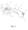
- Fig. 1
- ein erfindungsgemäßes tragbares Anzeigegerät in einer perspektivischen Ansicht und
- Fig. 2
- das tragbare Anzeigegerät gemäß
Fig. 1 in einer Explosionsdarstellung. - Das in
Fig. 1 dargestellte tragbare Anzeigegerät zur haptischen Anzeige von Orientierungsinformationen ist mit einem Gehäuse 1 und einem Tastelement 2 ausgestattet. Das Tastelement 2 ist relativ zum Gehäuse 1 verstellbar, wobei eine Antriebsanordnung 3 zum motorischen Verstellen des Tastelements 2 vorgesehen ist. Die Anordnung ist so getroffen, dass ein motorisches Verstellen des Tastelements 2 ertastbar ist und dadurch eine Orientierungsinformation haptisch anzeigbar ist. - Das Tastelement 2 zur haptischen Anzeige von Orientierungsinformationen ist mittels der Antriebsanordnung 3 relativ zum Gehäuse 1 verschwenkbar. Die hiermit verbundenen Vorteile wurden im allgemeinen Teil der Beschreibung erläutert.
- Das Tastelement 2 ist mittels der Antriebsanordnung 3 um eine Hochachse 4 verschwenkbar. In bevorzugter Ausgestaltung dient das Verschwenken des Tastelements 2 um die Hochachse 4 der haptischen Anzeige von Richtungsangaben. Ferner ist es vorgesehen, dass das Tastelement 2 mittels der Antriebsanordnung 3 um eine Querachse 5 verschwenkbar ist. Das Verschwenken des Tastelements 2 um die Querachse 5 dient vorzugsweise der haptischen Anzeige von Kollisions- und/oder Oberflächenangaben. Bei dem dargestellten Ausführungsbeispiel ist sowohl ein Verschwenken des Tastelements 2 um die Hochachse 4 als auch ein Verschwenken des Tastelements 2 um die Querachse 5 vorgesehen.
- In bevorzugter Ausgestaltung ist die Hochachse 4 im Gebrauch im Wesentlichen vertikal ausgerichtet und die Querachse 5 im Gebrauch im Wesentlichen horizontal ausgerichtet. Dabei ist die Querachse 5 vorzugsweise senkrecht zur Bewegungsrichtung des Benutzers ausgerichtet. Dies hat eine besonders intuitive Anzeige zur Folge. Die Anzeige von Richtungsinformationen erfolgt dann nämlich nach Art einer Kompassnadel. Das Verschwenken des Tastelements 2 um die Querachse 5 wird vom Benutzer gedanklich mit einer Oberflächenneigung verbunden, wodurch sich Oberflächen- und Kollisionsinformationen vorteilhaft anzeigen lassen.
- In einer nicht dargestellten bevorzugten Ausgestaltung ist das Tastelement 2 zusätzlich oder alternativ mittels der Antriebsanordnung 3 um eine Längsachse verschwenkbar. Die Längsachse ist vorzugsweise im Wesentlichen in der Bewegungsrichtung des Benutzers ausgerichtet. Hiermit lassen sich auch Richtungen senkrecht zur Bewegungsrichtung, also gewissermaßen Parallelverschiebungen im Hinblick auf die Bewegungsrichtung des Benutzers, anzeigen, die keine Komponente in Bewegungsrichtung aufweisen, was bei Ausweichmanövern vorteilhaft sein kann.
- Eine konstruktiv besonders einfache Ausgestaltung ergibt sich dadurch, dass das Tastelement 2 in einem ersten Lager 6 um die Hochachse 4 schwenkbar gelagert ist und dass das erste Lager 6 in einem zweiten Lager 7 um die Querachse 5 schwenkbar gelagert ist. Dieses "Ineinanderschachteln" der beiden Lager 6, 7 führt zu einer besonders kompakten Anordnung, wie
Fig. 2 zu entnehmen ist. - Bei der in
Fig. 2 dargestellten bevorzugten Ausgestaltung ist ein erster Antriebsmotor 6a für das motorische Verschwenken des Tastelements 2 um die Hochachse 4 und ein zweiter Antriebsmotor 7a für das Verschwenken des Tastelements 2 um die Querachse 5 vorgesehen. Bei den Antriebsmotoren 6a, 7a kann es sich um rotatorische Elektromotoren, um Solenoide o. dgl. handeln. Dabei treibt der erste Antriebsmotor 6a ein Ritzel 6b an, das unmittelbar mit dem Tastelement 2 verbunden ist. Das Tastelement 2 und der erste Antriebsmotor 6a befinden sich auf einem im zweiten Lager 7 gelagerten Träger, der mit einem Ritzel 7b verbunden ist. Das Ritzel 7b steht in antriebstechnischer Verbindung mit dem zweiten Antriebsmotor 7a. - Es sind auch andere konstruktive Varianten für die Realisierung der oben genannten Bewegungs-Freiheitsgrade sowie der motorischen Verstellung des Tastelements 2 denkbar. Besonders einfach zu realisieren ist die Lagerung des Tastelements 2 nach Art einer Kugel-Kugelpfannen-Lagerung. Dann ist das Tastelement 2 selbst oder eine mit dem Tastelement 2 verbundene Komponente jedenfalls zum Teil kugelförmig ausgestaltet. Damit lässt sich auf einfache Weise die oben beschriebene Verschwenkbarkeit um die Längsachse realisieren. Bei einer solchen Lagerung ist grundsätzlich eine motorische Verstellung des Tastelements 2 nach Art eines "inversen" Track-Balls denkbar. Mit "invers" ist hier gemeint, dass der Ball des Track-Balls nicht wie eigentlich üblich der Eingabe, sondern durch entsprechenden Antrieb durch die Antriebsanordnung 3 der Anzeige von Orientierungsinformationen dient. Die Bewegung des Tastelements 2 ist dann gewissermaßen in jeglicher Richtung möglich. Bei einer solchen Ausgestaltung ist die Realisierung der Antriebsanordnung 3 nach Art eines Kugelmotors denkbar.
- Die Lagerung des obigen zum Teil kugelförmigen Tastelements 2 kann auch in anderer Weise erfolgen, beispielsweise durch entsprechend angeordnete Lagerkugeln o. dgl.. Wesentlich ist bei einer solchen Ausgestaltung letztlich nur die Tatsache, dass das Tastelement 2 zum Teil kugelförmig ist.
- Von besonderer Bedeutung ist hier die Ausgestaltung des Tastelements 2, da das Tastelement 2 maßgeblich für eine schnelle und intuitive Anzeige der gewünschten Orientierungsinformationen ist.
- Das Tastelement 2 weist eine vorzugsweise stetig verlaufende Tastfläche 8 auf. Dies bedeutet, dass die Tastfläche 8 für sich genommen vorzugsweise keine ertastbaren Kanten o. dgl. aufweist. In bevorzugter Ausgestaltung ist es hier vorgesehen, dass an der Tastfläche 8 ein auf der Tastfläche 8 ertastbarer Tastkörper 9 angeordnet ist. Der Tastkörper 9 ermöglicht eine eindeutige haptische Anzeige der Verstellung des Tastelements 2. Hierfür ist der Tastkörper 9 als eine Erhebung auf der Tastfläche 8 oder als eine Vertiefung in der Tastfläche 8 ausgestaltet. Weitere Varianten zur Ausgestaltung des Tastkörpers 9 werden weiter unten gegeben.
- Es lässt sich der Darstellung in
Fig. 1 entnehmen, dass die Hochachse 4 hier durch die Tastfläche 8 hindurch verläuft und im Wesentlichen senkrecht zur Tastfläche 8 ausgerichtet ist. Dies ist insbesondere im Hinblick auf eine intuitive haptische Anzeige der Orientierungsinformationen von Vorteil. - Es ist der Darstellung in
Fig. 1 ferner zu entnehmen, dass sich die Tastfläche 8 im Wesentlichen unmittelbar an das Gehäuse 1 anschließt, wobei die Tastfläche 8 hier innerhalb einer Ausnehmung des Gehäuses 1 angeordnet ist. Ein subjektiv besonders angenehmer Eindruck lässt sich dadurch erreichen, dass der Übergang von der Tastfläche 8 zum Gehäuse 1 im Wesentlichen stetig ist. - Für den subjektiven Eindruck ist insbesondere die Ausgestaltung der Tastfläche 8 von Bedeutung. Je nach Ausgestaltung des Anzeigegeräts im Übrigen kann es vorteilhaft sein, die Tastfläche 8 und vorzugsweise den angrenzenden Gehäuseabschnitt im Wesentlichen konkav auszugestalten. Denkbar ist aber auch die im Wesentlichen konvexe Ausgestaltung der Tastfläche 8 und vorzugsweise des angrenzenden Gehäuseabschnitts. Die Tastfläche 8 kann beispielsweise die Fläche einer Kugel sein. Ferner kann es vorteilhaft sein, die Tastfläche 8 und vorzugsweise den angrenzenden Gehäuseabschnitt im Wesentlichen eben, also nach Art einer Scheibe, auszugestalten. Die Tastfläche 8 und der angrenzende Gehäuseabschnitt können aber auch derart zueinander komplementär ausgestaltet sein, dass die Tastfläche 8 konvex und der angrenzende Gehäuseabschnitt konkav oder umgekehrt ausgestaltet sind.
- Bei dem dargestellten Ausführungsbeispiel ist das Tastelement 2 um die Hochachse 4 einerseits und um die Querachse 5 andererseits schwenkbar ausgestaltet. Es kann alternativ oder zusätzlich auch sein, dass der Tastkörper 9 zur haptischen Anzeige von Orientierungsinformationen mittels der Antriebsanordnung 3 relativ zur Tastfläche 8, vorzugsweise senkrecht zur Tastfläche 8, verstellbar ist. Dabei ist es denkbar, dass der Tastkörper 9 senkrecht zur Tastfläche 8 verschwenkbar ist. Dadurch, dass hier eine Relativbewegung zwischen Tastfläche 8 und Tastkörper 9 realisiert ist, übernimmt der Tastkörper 9 gewissermaßen die Funktion eines nach vorne bzw. nach oben weisenden Pfeils o. dgl. Dies kann die intuitive Anzeige von Orientierungsinformationen weiter verbessern.
- Es lässt sich der Darstellung in
Fig. 1 ferner entnehmen, dass der Tastkörper 9 länglich ausgestaltet ist und hinsichtlich der Hochachse 4 radial angeordnet ist. Die längliche Ausgestaltung des Tastkörpers 9 verstärkt den subjektiven Eindruck, dass es sich bei dem Tastkörper 9 um einen Pfeil o. dgl. handelt. Um eine möglichst große Auslenkung des Tastkörpers 9 bei der Verstellung des Tastelements 2 zu erreichen, ist der Tastkörper 9 hinsichtlich der Verschwenkbarkeit um die Hochachse 4 außen am Tastelement 2 angeordnet. Damit lässt sich die Qualität der Anzeige von Orientierungsinformationen weiter verbessern. - Im dargestellten und insoweit bevorzugten Ausführungsbeispiel verläuft der Tastkörper 9 von der Hochachse 4 bis zum Außenrand des Tastelements 2. Es kann aber auch vorgesehen sein, dass der Tastkörper 9 durch die Hochachse 4 hindurch läuft. Grundsätzlich ist es auch denkbar, dass sich der Tastkörper 9 im Wesentlichen über die gesamte Breite der Tastfläche 8 erstreckt.
- Es wurde bereits angedeutet, dass der Form des Tastkörpers 9 für die Qualität der Anzeige besondere Bedeutung zukommt. In bevorzugter Ausgestaltung ist der Tastkörper 9 im Querschnitt gesehen in Richtung der Hochachse spitz zulaufend ausgestaltet. Es ergibt sich eine ertastbare Kante, die entlang der Längserstreckung des länglichen Tastkörpers 9 verläuft. Dies ist bei dem in
Fig. 1 dargestellten Ausführungsbeispiel der Fall. - Es kann aber auch vorgesehen sein, dass der Tastkörper 9 im Querschnitt gesehen rundlich ausgestaltet ist oder aber, dass der Tastkörper 9 im Querschnitt gesehen viereckig ausgestaltet ist. Versuche mit Probanten haben ergeben, dass eine eckige, insbesondere die spitz zulaufende Ausgestaltung des Tastkörpers zu besonders guten Ergebnissen bei der Anzeige von Orientierungsinformationen führt.
- Eine besonders komfortable Ausgestaltung ergibt sich dadurch, dass die Tastfläche 8 eine nutartige Ausformung aufweist, die im Wesentlichen hinsichtlich der Hochachse 4 in radialer Richtung verläuft und derart an die Form eines menschlichen Fingers angepasst ist, dass der Finger im Wesentlichen formschlüssig in der nutartigen Ausformung positionierbar ist. Der menschliche Finger blokkiert dann gewissermaßen das Verschwenken des Tastelements 2. Die resultierende Kraftwirkung vom Tastelement 2 auf den menschlichen Finger ermöglicht eine komfortable und gleichzeitig intuitive Anzeige der gewünschten Orientierungsinformationen.
- Die optimale Ausgestaltung des Tastelements 2 hängt wesentlich vom subjektiven Empfinden des Benutzers ab. Daher sind zahlreiche unterschiedliche Realisierungsmöglichkeiten für das Tastelement 2 denkbar. Entsprechend ist es vorteilhaft, wenn das Anzeigegerät insoweit modular ausgestaltet ist, dass unterschiedliche Tastelemente 2 zum Einsatz kommen können. Hierbei ist es vorzugsweise vorgesehen, dass der Austausch mit wenigen Handgriffen durch den Einsatz von Schnappverbindungen o. dgl. vonstatten geht. Grundsätzlich kann auch ein separater Austausch des Tastkörpers 9 vorgesehen sein.
- Bei dem dargestellten Ausführungsbeispiel ist das Gehäuse 1 als Einhand-Griff ausgestaltet, wobei das Gehäuse 1 im Wesentlichen länglich ausgestaltet ist und von einer menschlichen Hand umgriffen werden kann. Das Gehäuse 1 weist hier eine Form auf, die landläufig als knochenartig bezeichnet werden kann. Alternativ oder zusätzlich kann es vorgesehen sein, dass das Anzeigegerät an einer weiteren Komponente, beispielsweise an einem Rollstuhl o. dgl. befestigbar ist.
- Versuche mit Probanten haben ferner ergeben, dass der Daumen der menschlichen Hand für die Aufnahme haptischer Informationen besonders geeignet ist. Daher ist es in bevorzugter Ausgestaltung vorgesehen, dass bei Gebrauch das Tastelement 2 mit dem Daumen der das Gehäuse 1 greifenden Hand ertastbar ist.
- Zur Eingabe von Informationen, beispielsweise zum softwaremäßigen Scrollen zwischen verschiedenen Menüoptionen, ist es vorgesehen, dass unterhalb des Gehäuses 1 ein Scroll-Rad 9a vorgesehen ist, das in unmittelbarer Nähe des Zeigefingers der das Gehäuse 1 greifenden Hand angeordnet und von dieser betätigbar ist.
- Das tragbare Anzeigegerät kann neben der haptischen Anzeige von Orientierungsinformationen zahlreiche weitere Funktionen bereitstellen. Beispielsweise kann es vorgesehen sein, dass vorzugsweise am vorderen Ende 10 des Gehäuses 1 eine Kamera 11 angeordnet ist, deren Signale nach entsprechender Verarbeitung über das Tastelement 2 angezeigt werden können. In bevorzugter Ausgestaltung ist die Kamera 11 innerhalb des Gehäuses 1 angeordnet, wobei das Gehäuse 1 entsprechend einen transparenten Abschnitt 12 aufweist. Am vorzugsweise hinteren Ende 13 des Gehäuses 1 ist ggf. eine Schalteranordnung 14 angeordnet, die beispielsweise der Auswahl von Sensorfunktionen o. dgl. dienen kann.
- Die haptische Anzeige von Orientierungsfunktionen über das Tastelement 2 ist wesentlich davon abhängig, in welcher Lage sich das tragbare Anzeigegerät jeweils befindet. Zur Ermittlung dieser Lage ist es vorgesehen, dass vorzugsweise im mittleren Bereich 15 des Gehäuses 1 ein vorzugsweise elektronischer Kompass 16 oder ein Kreiselkompass 16 angeordnet ist. Hier sind auch andere Varianten denkbar. Beispielsweise können hier Neigungssensoren o. dgl. Anwendung finden.
- Weitere Versuche mit sehbehinderten Probanten haben ergeben, dass auf einen Blindenstock heutzutage (noch) nicht verzichtet werden kann. Sehbehinderte Personen sind schon zu lange an die Verwendung eines Blindenstocks, der üblicherweise als Taststock ausgestaltet ist, gewöhnt. Daher ist es vorzugsweise vorgesehen, dass das Gehäuse 1 am vorzugsweise vorderen Ende 10 einen Anschlussstutzen 17 für einen Taststock 18 aufweist.
- Der Darstellung in
Fig. 2 lässt sich der grundsätzliche Aufbau des tragbaren Anzeigegeräts in einer bevorzugten Ausgestaltung entnehmen. Das Gehäuse 1 ist hier im Wesentlichen zweiteilig ausgestaltet. Im mittleren Bereich ist neben dem Kompass 16 auch die Energieversorgung in Form von Akkus 19 angeordnet. Durch die knochenartige Ausgestaltung des Gehäuses 1 können am vorderen Ende 10 und an hinteren Ende 13 die oben beschriebenen zusätzlichen Komponenten angeordnet werden. Die dargestellte Struktur des tragbaren Anzeigegeräts führt zu einer hohen Kompaktheit und gleichzeitig zu geringen Realisierungskosten durch die geringe Teileanzahl. - Alternativ oder zusätzlich zu der Energieversorgung in Form von Akkus 19 kann eine Stromgeneratoranordnung vorgesehen sein. Ein Beispiel hierfür ist ein Dynamo, der mit einer Kurbel angetrieben wird. Ein anderes Beispiel besteht in der Umwandlung der Körperwärme des Benutzers durch entsprechende elektronische Bauelemente. Denkbar ist hier auch die Nutzung der kinetischen Energie, die bei der Bewegung des Anzeigegeräts entsteht.
- In besonders bevorzugter Ausgestaltung ist das erfindungsgemäße Anzeigegerät an die Fähigkeiten und Eigenschaften des Benutzers anpassbar. Dies betrifft insbesondere die Verstellcharakteristik des Tastelements 2. Beispielsweise können die Verstellgeschwindigkeit des Tastelements 2 sowie dessen maximale Auslenkung unterschiedlich konfiguriert werden.
- In weiter bevorzugter Ausgestaltung ist es vorgesehen, dass Daten, beispielsweise Kartendaten oder eingelernte Daten, zwischen zwei erfindungsgemäßen Anzeigegeräten austauschbar sind. Hierfür ist das erfindungsgemäße Anzeigegerät vorzugsweise mit einer Infrarotschnittstelle o. dgl. ausgestattet.
- Grundsätzlich kann das Tastelement 2 auch zur Eingabe, und nicht nur zur Anzeige von Information dienen. Besonders einfach zu realisieren ist aber eine Ausgestaltung, bei der das Tastelement 2 ausschließlich der Anzeige von Informationen und nicht der Eingabe von Informationen dient.
- Sofern das Tastelement 2 auch zur Eingabe von Informationen dienen soll, ist es vorzugsweise so, dass das Tastelement 2 manuell benutzergeführt verstellbar ist und dass eine Sensoranordnung zur Detektion einer manuellen benutzergeführten Verstellung des Tastelements 2 vorgesehen ist. Ein manuelles Verschwenken des Tastelements 2 lässt sich dann also sensorisch erfassen. Das kann bei der im Folgenden beschriebenen Master-Slave-Anordnung vorteilhaft sein.
- Vorschlagsgemäß ist es nun vorgesehen, dass grundsätzlich zwei oben genannte Anzeigegeräte parallel im Einsatz sind. Das eine Anzeigegerät wird dabei als Mastergerät bezeichnet, während das andere Anzeigegerät als Slavegerät bezeichnet wird. Dabei ist es so, dass sich das Tastelement 2 des Slavegeräts durch eine manuelle, benutzergeführte Verstellung des Tastelements 2 des Mastergeräts motorisch verstellen lässt. Das Mastergerät dient hier also als Eingabegerät. Man könnte auch sagen, dass das Slavegerät durch das Mastergerät ferngesteuert wird. Damit kann beispielsweise eine sehbehinderte Person mit dem Slavegerät ausgestattet und über das Mastergerät gewissermaßen ferngesteuert werden. Das Mastergerät wird entsprechend von einer nicht sehbehinderten Person bedient. Auf aufwendige Sensoren kann hier vollständig verzichtet werden. Diese Art der "Fernsteuerung" kann auch bei allen anderen denkbaren Anwendungsfällen für das obige Anzeigegerät vorteilhaft sein.
- Grundsätzlich kann es sich bei dem Mastergerät um ein oben beschriebenes Anzeigegerät handeln, das zusätzlich der Eingabe von Orientierungsinformationen dient. In diesem Zusammenhang ist es in fertigungstechnischer Hinsicht besonders vorteilhaft, wenn das Mastergerät und das Slavegerät identisch aufgebaut sind. Dann ist ein Schalter o. dgl. vorzusehen, mit dem festgelegt werden kann, ob es sich bei dem jeweiligen Gerät um das Mastergerät oder um das Slavegerät handelt. Bei der identischen Ausgestaltung von Mastergerät und Slavegerät ist die Möglichkeit gegeben, dass die sehbehinderte Person über das Slavegerät ebenfalls Eingaben über das Tastelement tätigen kann, um der nicht sehbehinderten Person bestimmte Rückmeldungen zu geben.
- Es kann sich bei dem Mastergerät aber auch um Gerät handeln, das ausschließlich der Eingabe von Orientierungsinformationen dient. Eine Antriebsanordnung ist bei dem Mastergerät dann nicht vorgesehen, was zu besonders geringen Kosten führt.
- In allen Fällen ist es so, dass sich das Tastelement 2 des Slavegeräts durch eine manuelle, benutzergeführte Verstellung des Tastelements 2 des Mastergeräts ferngesteuert motorisch verstellen lässt. Soll die sehbehinderte Person beispielsweise nach links geführt werden, so verschwenkt die nicht sehbehinderte Person das Tastelement 2 am Mastergerät nach links, was anschließend zu einem entsprechenden Verschwenken des Tastelements 2 des Slavegeräts nach links führt. Diese haptische Anzeige wird von der sehbehinderten Person registriert, so dass sie ihre Bewegungsrichtung entsprechend nach links ändern kann. Bei dieser Fernsteuerung handelt es sich vorzugsweise um eine drahtlose Fernsteuerung, die beispielsweise auf Funk, Infrarot o. dgl. basiert. Für die Realisierung der Fernsteuerung weisen das Mastergerät und das Slavegerät jeweils eine Kommunikationsanordnung auf, mit der eine Datenverbindung zwischen den beiden Geräten aufgebaut werden kann.
- Eine manuelle benutzergeführte Verstellung des Tastelements 2 des Mastergeräts wird von der dem Tastelement 2 zugeordneten Sensoranordnung detektiert und über die Kommunikationsanordnung an das Slavegerät übermittelt. Das Tastelement 2 des Slavegeräts wird mittels der zugeordneten Antriebsanordnung 3 entsprechend verstellt, so dass die eingegebene Orientierungsinformation am Slave gerät haptisch angezeigt wird. Dabei ist es vorzugsweise so, dass eine Verstellung des Tastelements 2 am Mastergerät zu einer identischen Verstellung des Tastelements 2 auf dem Slavegerät führt. Es ist aber auch denkbar, dass hier unterschiedliche Empfindlichkeiten einstellbar sind.
- In bevorzugter Ausgestaltung ist das motorische Verschwenken des Tastelements 2 um die Hochachse 4 einer Richtungsinformation zugeordnet, wobei das motorische Verschwenken des Tastelements 2 um die Querachse vorzugsweise einer Kollisions- und/oder Oberflächeninformation zugeordnet ist.
- Entsprechend ist vorzugsweise ein Navigationsmodul vorgesehen, wobei Richtungsinformationen vom Navigationsmodul über das motorische Verschwenken des Tastelements 2 um die Hochachse 4 abgebbar sind.
- Alternativ oder zusätzlich kann ein Kollisionsvermeidungsmodul vorgesehen sein, wobei Kollisions- und Oberflächeninformationen vom Kollisionsvermeidungsmodul über das motorische Verschwenken des Tastelements 2 um die Querachse 5 abgebbar sind.
- Die oben beschriebene haptische Anzeige über das Tastelement 2 kann ergänzt werden durch andere Anzeigen wie Sprachausgabe, Tonausgabe o. dgl. Es kann auch vorgesehen sein, dass das motorische Verstellen des Tastelements 2 impulsartig erfolgt, wodurch über die Impulsform und -länge ebenfalls zusätzliche Informationen an den Benutzer abgebbar sind. Bei drohender Kollisionsgefahr kann es vorgesehen sein, dass das Verschwenken des Tastelements 2 um die Querachse in kurzen - und damit alarmierenden - Impulsen durchgeführt wird. Bei einer weiteren bevorzugten Ausgestaltung werden solche zusätzlichen Informationen durch die Verstellgeschwingigkeit und/oder den Verstellweg des Tastelements 2 angezeigt. Damit lassen sich die gewünschten Informationen stufenlos und damit sehr präzise anzeigen. Es ist ferner denkbar, dass das Anzeigegerät mit einem Vibrationsgenerator ausgestattet ist, um diese zusätzlichen Informationen an den Benutzer abzugeben.
- Nach der vorschlagsgemäßen Lehre lässt sich das Tastelement 2 des Slavegeräts durch eine manuelle, benutzergeführte Verstellung des Tastelements 2 des Mastergeräts ferngesteuert motorisch verstellen. Das Tastelement 2 der beiden Geräte kann wie oben beschrieben, muss aber nicht in mehreren Freiheitsgraden verstellbar sein. Denkbar ist eine Verschwenkbarkeit der Tastelemente 2 zur haptischen Anzeige bzw. Eingabe von Richtungsinformationen ausschließlich um eine Hochachse 4. Hinsichtlich der Ausgestaltung des Mastergeräts und des Slavegeräts darf in vollem Umfange auf die obigen Ausführungen verwiesen werden.
- Es darf darauf hingewiesen werden, dass sich das erfindungsgemäße tragbare Anzeigegerät für die Unterstützung sehbehinderter Personen eignet. Dies gilt insbesondere dann, wenn die sehbehinderte Person zusätzlich ein nur eingeschränktes Hörvermögen aufweist. Grundsätzlich ist das tragbare Anzeigegerät aber für jeden Bereich anwendbar, in dem unzureichende visuelle Informationen vorliegen. Als Beispiel wurde die Unterstützung von Feuerwehrleuten bei hoher Rauchentwicklung genannt. Andere Beispiele sind die Unterstützung von Tauchern, Seglern oder aber Piloten, wenn unzureichende Sichtverhältnisse herrschen. Das Anzeigegerät kann grundsätzlich auch als Anzeigegerät für einen Personal Computer o. dgl. dienen, beispielsweise im Rahmen der Vorbereitung einer sehbehinderten Person auf die abzulaufende Wegstrecke, oder aber im Rahmen eines Computerspiels.
- Letztlich kann das erfindungsgemäße tragbare Anzeigegerät also mit beliebigen Geräten gekoppelt werden, die Orientierungsinformationen jeglicher Art liefern. Insoweit handelt es sich bei dem erfindungsgemäßen Anzeigegerät vorzugsweise um eine Add-On-Komponente, beispielsweise für GPS-Navigationssysteme o. dgl.
- Es darf schließlich darauf hingewiesen werden, dass das obige Anzeigegerät, die Mobilitätshilfe sowie die Mobilitätshilfsanordnung diesseits auch als Personal Travel Assistant (PETRA) bezeichnet werden.
Claims (10)
- Tragbare Mobilitätshilfsanordnung mit einem tragbaren Anzeigegerät zur haptischen Anzeige und. ggf. Eingabe von Orientierungsinformationen - Slavegerät - und einem weiteren tragbaren Gerät zur haptischen Eingabe und ggf. Anzeige von Orientierungsinformationen - Mastergerät -, wobei das Slavegerät und das Mastergerät zur Anzeige bzw. Eingabe von Orientierungsinformationen jeweils ein Tastelement (2) aufweisen und wobei sich das Tastelement (2) des Slavegeräts (2) durch eine manuelle, benutzergeführte Verstellung des Tastelements (2) des Mastergeräts ferngesteuert motorisch verstellen lässt.
- Tragbare Mobilitätshilfsanordnung nach Anspruch 1, dadurch gekennzeichnet, dass das Tastelement (2) zur Anzeige von Orientierungsinformationen schwenkbar ausgestaltet ist.
- Tragbare Mobilitätshilfsanordnung nach Anspruch 1 oder 2, dadurch gekennzeichnet, dass das Mastergerät und das Slavegerät identisch aufgebaut sind.
- Tragbare Mobilitätshilfsanordnung nach Anspruch 3, dadurch gekennzeichnet, dass ein Schalter oder dergleichen vorgesehen ist, mit dem festgelegt werden kann, ob es sich bei dem jeweiligen Gerät um das Mastergerät oder um das Slavegerät handelt.
- Tragbare Mobilitätshilfsanordnung nach einem der vorhergehenden Ansprüche, dadurch gekennzeichnet, dass das Mastergerät ausschließlich der Eingabe von Orientierungsinformationen dient und keine Antriebsanordnung zur motorischen Verstellung des Tastelements vorgesehen ist.
- Tragbare Mobilitätshilfsanordnung nach einem der vorhergehenden Ansprüche, dadurch gekennzeichnet, dass das Mastergerät und das Slavegerät jeweils eine Kommunikationsanordnung aufweisen, mit der eine Datenverbindung zwischen den beiden Geräten aufgebaut werden kann, vorzugsweise, dass die Datenverbindung drahtlos vorgesehen ist und beispielsweise auf Funk, Infrarot oder dergleichen basiert.
- Tragbare Mobilitätshilfsanordnung nach einem der vorhergehenden Ansprüche, dadurch gekennzeichnet, dass eine Verstellung des Tastelements (2) am Mastergerät abgesehen von einer ggf. vorgegebenen Einstellbarkeit unterschiedlicher Empfindlichkeiten zu einer identischen Verstellung des Tastelements (2) auf dem Slavegerät führt.
- Tragbare Mobilitätshilfsanordnung nach einem der vorhergehenden Ansprüche, dadurch gekennzeichnet, dass das Mastergerät und/oder das Slavegerät als tragbares Anzeigegerät zur haptischen Anzeige und ggf. Eingabe von Orientierungsinformationen mit einem Gehäuse (1) und einem Tastelement (2) ausgestaltet ist bzw. sind, dass das Tastelement (2) relativ zum Gehäuse (1) verstellbar ist, dass eine Antriebsanordnung (3) zum motorischen Verstellen des Tastelements (2) vorgesehen ist und dass ein motorisches Verstellen des Tastelements (2) ertastbar ist und dadurch eine Orientierungsinformation haptisch anzeigbar ist, dass das Tastelement (2) zur haptischen Anzeige von Orientierungsinformationen mittels der Antriebsanordnung (3) relativ zum Gehäuse (1) verschwenkbar ist und dass das Tastelement (2) mittels der Antriebsanordnung (3) vorzugsweise zur haptischen Anzeige von Richtungsinformationen um eine Hochachse (4) verschwenkbar ist und dass das Tastelement (2) mittels der Antriebsanordnung (3) vorzugsweise zur haptischen Anzeige von Kollisions- und/oder Oberflächeninformationen um eine Querachse (5) verschwenkbar ist.
- Verwendung einer tragbaren Mobilitätshilfsanordnung nach einem der Ansprüche 1 bis 8 zur Führung einer sehbehinderten Person durch eine nicht-sehbehinderte Person, wobei das Slavegerät für die Bedienung durch die sehbehinderte Person und das Mastergerät für die Bedienung durch die nicht-sehbehinderte Person vorgesehen ist.
- Verwendung einer tragbaren Mobilitätshilfsanordnung nach Anspruch 9, wobei die sehbehinderte Person über das Slavegerät Eingaben über das Tastelement tätigt, um der nicht-sehbehinderten Person bestimmte Rückmeldungen zu geben.
Applications Claiming Priority (2)
| Application Number | Priority Date | Filing Date | Title |
|---|---|---|---|
| DE202006000980U DE202006000980U1 (de) | 2006-01-20 | 2006-01-20 | Tragbares Anzeigegerät zur haptischen Anzeige von Orientierungsinformationen |
| EP07001130A EP1813244B1 (de) | 2006-01-20 | 2007-01-19 | Tragbares Anzeigegerät zur haptischen Anzeige von Orientierungsinformationen |
Related Parent Applications (2)
| Application Number | Title | Priority Date | Filing Date |
|---|---|---|---|
| EP07001130A Division EP1813244B1 (de) | 2006-01-20 | 2007-01-19 | Tragbares Anzeigegerät zur haptischen Anzeige von Orientierungsinformationen |
| EP07001130.9 Division | 2007-01-19 |
Publications (2)
| Publication Number | Publication Date |
|---|---|
| EP2074980A1 true EP2074980A1 (de) | 2009-07-01 |
| EP2074980B1 EP2074980B1 (de) | 2013-03-27 |
Family
ID=37903947
Family Applications (2)
| Application Number | Title | Priority Date | Filing Date |
|---|---|---|---|
| EP07001130A Not-in-force EP1813244B1 (de) | 2006-01-20 | 2007-01-19 | Tragbares Anzeigegerät zur haptischen Anzeige von Orientierungsinformationen |
| EP09004658A Not-in-force EP2074980B1 (de) | 2006-01-20 | 2007-01-19 | Mobilitätshilfsanordnung |
Family Applications Before (1)
| Application Number | Title | Priority Date | Filing Date |
|---|---|---|---|
| EP07001130A Not-in-force EP1813244B1 (de) | 2006-01-20 | 2007-01-19 | Tragbares Anzeigegerät zur haptischen Anzeige von Orientierungsinformationen |
Country Status (5)
| Country | Link |
|---|---|
| EP (2) | EP1813244B1 (de) |
| AT (1) | ATE427093T1 (de) |
| DE (2) | DE202006000980U1 (de) |
| DK (2) | DK1813244T3 (de) |
| ES (2) | ES2324838T3 (de) |
Families Citing this family (8)
| Publication number | Priority date | Publication date | Assignee | Title |
|---|---|---|---|---|
| DE102010046291B4 (de) * | 2010-09-22 | 2016-03-10 | Aissa Zouhri | Orientierungshilfevorrichtung |
| JP5486481B2 (ja) * | 2010-12-06 | 2014-05-07 | パナソニック株式会社 | 頭皮ケア装置 |
| DE102012008784A1 (de) | 2012-05-07 | 2013-11-07 | I-Cane Social Technology Bv | Haptische Benutzerschnittstelle |
| DE102013016944A1 (de) | 2013-10-14 | 2015-04-16 | I-Cane Social Technology Bv | Assistenzsystem |
| IN2014DE00388A (de) * | 2014-02-12 | 2015-08-14 | Indian Inst Technology Delhi | |
| CN107789167A (zh) * | 2017-11-22 | 2018-03-13 | 佛山市海科云筹信息技术有限公司 | 一种能帮助视障人士准确指示方位的盲杖及方法 |
| CN107913159A (zh) * | 2017-11-22 | 2018-04-17 | 佛山市海科云筹信息技术有限公司 | 一种通过红外信号准确指示方位的盲杖及方法 |
| CN119345004B (zh) * | 2024-10-28 | 2026-04-24 | 广州大学 | 一种智能交互系统及智能导盲拐杖 |
Citations (6)
| Publication number | Priority date | Publication date | Assignee | Title |
|---|---|---|---|---|
| US3736551A (en) | 1970-11-16 | 1973-05-29 | Us Navy | Swimmers tactile command navigation apparatus |
| US5047952A (en) | 1988-10-14 | 1991-09-10 | The Board Of Trustee Of The Leland Stanford Junior University | Communication system for deaf, deaf-blind, or non-vocal individuals using instrumented glove |
| DE19517649A1 (de) | 1995-05-17 | 1996-11-21 | Thomas Rupp | Vorrichtung zum Übermitteln von Zeichen und Buchstaben von einer Datenverarbeitungsanlage an eine taubblinde Person |
| WO1997015265A1 (en) | 1995-10-25 | 1997-05-01 | Techn-O-Tape B.V. | White stick for blind persons |
| GB2320315A (en) | 1996-12-14 | 1998-06-17 | Heping He | A keyboard glove for use by the blind |
| DE102004042884A1 (de) | 2004-09-04 | 2006-03-23 | Hönicke, Bernd | Kommunikationsgerät für taubblinde Personen |
Family Cites Families (3)
| Publication number | Priority date | Publication date | Assignee | Title |
|---|---|---|---|---|
| DE589531C (de) * | 1932-11-08 | 1933-12-13 | Fritz Kreis | Blindenkompass |
| US6298010B1 (en) * | 1997-04-30 | 2001-10-02 | Maria Ritz | Orientation aid for the blind and the visually disabled |
| DE20214852U1 (de) * | 2002-09-09 | 2003-02-13 | Kaphahn, Alexandra, Dipl.-Ing., 52072 Aachen | Tragbare Mobilitätshilfe für sehbehinderte Personen |
-
2006
- 2006-01-20 DE DE202006000980U patent/DE202006000980U1/de not_active Expired - Lifetime
-
2007
- 2007-01-19 DK DK07001130T patent/DK1813244T3/da active
- 2007-01-19 DK DK09004658.2T patent/DK2074980T3/da active
- 2007-01-19 EP EP07001130A patent/EP1813244B1/de not_active Not-in-force
- 2007-01-19 AT AT07001130T patent/ATE427093T1/de active
- 2007-01-19 ES ES07001130T patent/ES2324838T3/es active Active
- 2007-01-19 DE DE502007000543T patent/DE502007000543D1/de active Active
- 2007-01-19 EP EP09004658A patent/EP2074980B1/de not_active Not-in-force
- 2007-01-19 ES ES09004658T patent/ES2412431T3/es active Active
Patent Citations (6)
| Publication number | Priority date | Publication date | Assignee | Title |
|---|---|---|---|---|
| US3736551A (en) | 1970-11-16 | 1973-05-29 | Us Navy | Swimmers tactile command navigation apparatus |
| US5047952A (en) | 1988-10-14 | 1991-09-10 | The Board Of Trustee Of The Leland Stanford Junior University | Communication system for deaf, deaf-blind, or non-vocal individuals using instrumented glove |
| DE19517649A1 (de) | 1995-05-17 | 1996-11-21 | Thomas Rupp | Vorrichtung zum Übermitteln von Zeichen und Buchstaben von einer Datenverarbeitungsanlage an eine taubblinde Person |
| WO1997015265A1 (en) | 1995-10-25 | 1997-05-01 | Techn-O-Tape B.V. | White stick for blind persons |
| GB2320315A (en) | 1996-12-14 | 1998-06-17 | Heping He | A keyboard glove for use by the blind |
| DE102004042884A1 (de) | 2004-09-04 | 2006-03-23 | Hönicke, Bernd | Kommunikationsgerät für taubblinde Personen |
Non-Patent Citations (1)
| Title |
|---|
| "Hauptkatalog 2005/2006", 2005, CONRAD ELECTRONIC GMBH, XP002440409 * |
Also Published As
| Publication number | Publication date |
|---|---|
| EP1813244B1 (de) | 2009-04-01 |
| EP1813244A2 (de) | 2007-08-01 |
| EP2074980B1 (de) | 2013-03-27 |
| DK1813244T3 (da) | 2009-07-06 |
| ES2412431T3 (es) | 2013-07-11 |
| DE502007000543D1 (de) | 2009-05-14 |
| ES2324838T3 (es) | 2009-08-17 |
| DK2074980T3 (da) | 2013-07-01 |
| ATE427093T1 (de) | 2009-04-15 |
| DE202006000980U1 (de) | 2007-05-24 |
| EP1813244A3 (de) | 2007-09-05 |
Similar Documents
| Publication | Publication Date | Title |
|---|---|---|
| EP2074980B1 (de) | Mobilitätshilfsanordnung | |
| DE69816319T2 (de) | Multischaltereinrichtung für die steurung von fahrzeugsubsystemen | |
| CH660554A5 (de) | Einrichtung zum ansteuern eines elektrisch betriebenen apparates. | |
| DE2401366A1 (de) | Anzeigesystem mit positionsindikator | |
| DE69814713T2 (de) | Eingabevorrichtung zur Verbesserung einer Mensch-Maschine-Schnittstelle | |
| AT520408B1 (de) | Fernsteuerung für Kameras | |
| EP1518725A2 (de) | Vorrichtung und Verfahren zum Einstellen von Sollwerten einer Kraftfahrzeugklimaanlage | |
| EP0021089A2 (de) | Arbeitsplatzeinheit | |
| EP0809223B1 (de) | Vorrichtung zum Übermitteln von Zeichen und Buchstaben von einer Datenverarbeitungsanlage an eine taubblinde Person | |
| DE102018207734B4 (de) | Rückmeldeeinrichtung für ein Kraftfahrzeug, Kraftfahrzeug und Verfahren zum Ausgeben einer Rückmeldung | |
| DE1803195A1 (de) | Visuelles Lehrgeraet | |
| AT412745B (de) | Steuereinheit | |
| DE102008028365A1 (de) | Rotorfluggerät mit einer Steuereinrichtung zum Generieren von Steuerbefehlen | |
| EP3960594A1 (de) | Verfahren zum betreiben eines hilfsantriebs für einen anhänger, system zum antreiben wenigstens eines rads eines solchen anhängers sowie computerprogrammprodukt und datenträger zum ausführen der schritte des verfahrens | |
| DE102007038755A1 (de) | Sport-, Therapie- oder Spielgerät | |
| DE102007057924A1 (de) | Verfahren für eine blindengerechte Benutzerschnittstelle zur Navigation und Kontrolle von Computern oder elektronisch- bzw. computergesteuerten Geräten | |
| DE2204867C3 (de) | Einrichtung zum Übermitteln von Bildinformationen | |
| WO2015161965A1 (de) | Mobiles medizingerät | |
| DE102020123568B3 (de) | Kommunikationswerkzeug | |
| DE102010048504B3 (de) | Gebetshilfevorrichtung | |
| DE10357774A1 (de) | Eingabevorrichtung | |
| DE102004048888B4 (de) | Bedieneinrichtung | |
| WO2017178475A1 (de) | Therapiegerät, therapiesystem und deren verwendung sowie verfahren zur identifizierung eines objekts | |
| DE202010014301U1 (de) | Gebetshilfevorrichtung | |
| DE4315265C1 (de) | Kopfgesteuerte Bedieneinheit für Computersysteme |
Legal Events
| Date | Code | Title | Description |
|---|---|---|---|
| PUAI | Public reference made under article 153(3) epc to a published international application that has entered the european phase |
Free format text: ORIGINAL CODE: 0009012 |
|
| AC | Divisional application: reference to earlier application |
Ref document number: 1813244 Country of ref document: EP Kind code of ref document: P |
|
| AK | Designated contracting states |
Kind code of ref document: A1 Designated state(s): AT BE BG CH CY CZ DE DK EE ES FI FR GB GR HU IE IS IT LI LT LU LV MC NL PL PT RO SE SI SK TR |
|
| RAP3 | Party data changed (applicant data changed or rights of an application transferred) |
Owner name: STICHTING ONTWIKKELING EN VERVAARDIGING VAN HULPMI |
|
| 17P | Request for examination filed |
Effective date: 20091222 |
|
| 17Q | First examination report despatched |
Effective date: 20100125 |
|
| AKX | Designation fees paid |
Designated state(s): AT BE BG CH CY CZ DE DK EE ES FI FR GB GR HU IE IS IT LI LT LU LV MC NL PL PT RO SE SI SK TR |
|
| RIC1 | Information provided on ipc code assigned before grant |
Ipc: G09B 21/00 20060101ALI20120830BHEP Ipc: A61H 3/06 20060101AFI20120830BHEP |
|
| GRAP | Despatch of communication of intention to grant a patent |
Free format text: ORIGINAL CODE: EPIDOSNIGR1 |
|
| GRAS | Grant fee paid |
Free format text: ORIGINAL CODE: EPIDOSNIGR3 |
|
| GRAA | (expected) grant |
Free format text: ORIGINAL CODE: 0009210 |
|
| AC | Divisional application: reference to earlier application |
Ref document number: 1813244 Country of ref document: EP Kind code of ref document: P |
|
| AK | Designated contracting states |
Kind code of ref document: B1 Designated state(s): AT BE BG CH CY CZ DE DK EE ES FI FR GB GR HU IE IS IT LI LT LU LV MC NL PL PT RO SE SI SK TR |
|
| REG | Reference to a national code |
Ref country code: GB Ref legal event code: FG4D Free format text: NOT ENGLISH |
|
| REG | Reference to a national code |
Ref country code: CH Ref legal event code: EP |
|
| REG | Reference to a national code |
Ref country code: AT Ref legal event code: REF Ref document number: 602898 Country of ref document: AT Kind code of ref document: T Effective date: 20130415 |
|
| REG | Reference to a national code |
Ref country code: IE Ref legal event code: FG4D Free format text: LANGUAGE OF EP DOCUMENT: GERMAN |
|
| REG | Reference to a national code |
Ref country code: DE Ref legal event code: R096 Ref document number: 502007011534 Country of ref document: DE Effective date: 20130523 |
|
| REG | Reference to a national code |
Ref country code: DK Ref legal event code: T3 |
|
| REG | Reference to a national code |
Ref country code: ES Ref legal event code: FG2A Ref document number: 2412431 Country of ref document: ES Kind code of ref document: T3 Effective date: 20130711 |
|
| REG | Reference to a national code |
Ref country code: SE Ref legal event code: TRGR |
|
| PG25 | Lapsed in a contracting state [announced via postgrant information from national office to epo] |
Ref country code: LT Free format text: LAPSE BECAUSE OF FAILURE TO SUBMIT A TRANSLATION OF THE DESCRIPTION OR TO PAY THE FEE WITHIN THE PRESCRIBED TIME-LIMIT Effective date: 20130327 Ref country code: BG Free format text: LAPSE BECAUSE OF FAILURE TO SUBMIT A TRANSLATION OF THE DESCRIPTION OR TO PAY THE FEE WITHIN THE PRESCRIBED TIME-LIMIT Effective date: 20130627 |
|
| REG | Reference to a national code |
Ref country code: LT Ref legal event code: MG4D |
|
| REG | Reference to a national code |
Ref country code: NL Ref legal event code: T3 |
|
| PG25 | Lapsed in a contracting state [announced via postgrant information from national office to epo] |
Ref country code: GR Free format text: LAPSE BECAUSE OF FAILURE TO SUBMIT A TRANSLATION OF THE DESCRIPTION OR TO PAY THE FEE WITHIN THE PRESCRIBED TIME-LIMIT Effective date: 20130628 Ref country code: LV Free format text: LAPSE BECAUSE OF FAILURE TO SUBMIT A TRANSLATION OF THE DESCRIPTION OR TO PAY THE FEE WITHIN THE PRESCRIBED TIME-LIMIT Effective date: 20130327 Ref country code: SI Free format text: LAPSE BECAUSE OF FAILURE TO SUBMIT A TRANSLATION OF THE DESCRIPTION OR TO PAY THE FEE WITHIN THE PRESCRIBED TIME-LIMIT Effective date: 20130327 |
|
| PG25 | Lapsed in a contracting state [announced via postgrant information from national office to epo] |
Ref country code: CZ Free format text: LAPSE BECAUSE OF FAILURE TO SUBMIT A TRANSLATION OF THE DESCRIPTION OR TO PAY THE FEE WITHIN THE PRESCRIBED TIME-LIMIT Effective date: 20130327 Ref country code: EE Free format text: LAPSE BECAUSE OF FAILURE TO SUBMIT A TRANSLATION OF THE DESCRIPTION OR TO PAY THE FEE WITHIN THE PRESCRIBED TIME-LIMIT Effective date: 20130327 Ref country code: SK Free format text: LAPSE BECAUSE OF FAILURE TO SUBMIT A TRANSLATION OF THE DESCRIPTION OR TO PAY THE FEE WITHIN THE PRESCRIBED TIME-LIMIT Effective date: 20130327 Ref country code: RO Free format text: LAPSE BECAUSE OF FAILURE TO SUBMIT A TRANSLATION OF THE DESCRIPTION OR TO PAY THE FEE WITHIN THE PRESCRIBED TIME-LIMIT Effective date: 20130327 Ref country code: IS Free format text: LAPSE BECAUSE OF FAILURE TO SUBMIT A TRANSLATION OF THE DESCRIPTION OR TO PAY THE FEE WITHIN THE PRESCRIBED TIME-LIMIT Effective date: 20130727 Ref country code: PT Free format text: LAPSE BECAUSE OF FAILURE TO SUBMIT A TRANSLATION OF THE DESCRIPTION OR TO PAY THE FEE WITHIN THE PRESCRIBED TIME-LIMIT Effective date: 20130729 |
|
| PG25 | Lapsed in a contracting state [announced via postgrant information from national office to epo] |
Ref country code: PL Free format text: LAPSE BECAUSE OF FAILURE TO SUBMIT A TRANSLATION OF THE DESCRIPTION OR TO PAY THE FEE WITHIN THE PRESCRIBED TIME-LIMIT Effective date: 20130327 Ref country code: CY Free format text: LAPSE BECAUSE OF FAILURE TO SUBMIT A TRANSLATION OF THE DESCRIPTION OR TO PAY THE FEE WITHIN THE PRESCRIBED TIME-LIMIT Effective date: 20130327 |
|
| PLBE | No opposition filed within time limit |
Free format text: ORIGINAL CODE: 0009261 |
|
| STAA | Information on the status of an ep patent application or granted ep patent |
Free format text: STATUS: NO OPPOSITION FILED WITHIN TIME LIMIT |
|
| PG25 | Lapsed in a contracting state [announced via postgrant information from national office to epo] |
Ref country code: IT Free format text: LAPSE BECAUSE OF FAILURE TO SUBMIT A TRANSLATION OF THE DESCRIPTION OR TO PAY THE FEE WITHIN THE PRESCRIBED TIME-LIMIT Effective date: 20130327 |
|
| PGFP | Annual fee paid to national office [announced via postgrant information from national office to epo] |
Ref country code: LU Payment date: 20140123 Year of fee payment: 8 |
|
| 26N | No opposition filed |
Effective date: 20140103 |
|
| REG | Reference to a national code |
Ref country code: DE Ref legal event code: R097 Ref document number: 502007011534 Country of ref document: DE Effective date: 20140103 |
|
| PGFP | Annual fee paid to national office [announced via postgrant information from national office to epo] |
Ref country code: CH Payment date: 20140121 Year of fee payment: 8 Ref country code: DK Payment date: 20140121 Year of fee payment: 8 Ref country code: NL Payment date: 20140121 Year of fee payment: 8 Ref country code: SE Payment date: 20140121 Year of fee payment: 8 Ref country code: FI Payment date: 20140113 Year of fee payment: 8 Ref country code: BE Payment date: 20140121 Year of fee payment: 8 Ref country code: DE Payment date: 20140121 Year of fee payment: 8 |
|
| PGFP | Annual fee paid to national office [announced via postgrant information from national office to epo] |
Ref country code: AT Payment date: 20140113 Year of fee payment: 8 Ref country code: ES Payment date: 20140129 Year of fee payment: 8 Ref country code: FR Payment date: 20140123 Year of fee payment: 8 |
|
| PGFP | Annual fee paid to national office [announced via postgrant information from national office to epo] |
Ref country code: GB Payment date: 20140121 Year of fee payment: 8 |
|
| PG25 | Lapsed in a contracting state [announced via postgrant information from national office to epo] |
Ref country code: MC Free format text: LAPSE BECAUSE OF FAILURE TO SUBMIT A TRANSLATION OF THE DESCRIPTION OR TO PAY THE FEE WITHIN THE PRESCRIBED TIME-LIMIT Effective date: 20130327 |
|
| REG | Reference to a national code |
Ref country code: IE Ref legal event code: MM4A |
|
| PG25 | Lapsed in a contracting state [announced via postgrant information from national office to epo] |
Ref country code: IE Free format text: LAPSE BECAUSE OF NON-PAYMENT OF DUE FEES Effective date: 20140119 |
|
| PG25 | Lapsed in a contracting state [announced via postgrant information from national office to epo] |
Ref country code: BE Free format text: LAPSE BECAUSE OF NON-PAYMENT OF DUE FEES Effective date: 20150131 |
|
| REG | Reference to a national code |
Ref country code: DE Ref legal event code: R119 Ref document number: 502007011534 Country of ref document: DE |
|
| REG | Reference to a national code |
Ref country code: NL Ref legal event code: V1 Effective date: 20150801 |
|
| REG | Reference to a national code |
Ref country code: CH Ref legal event code: PL |
|
| PG25 | Lapsed in a contracting state [announced via postgrant information from national office to epo] |
Ref country code: LU Free format text: LAPSE BECAUSE OF NON-PAYMENT OF DUE FEES Effective date: 20150119 |
|
| REG | Reference to a national code |
Ref country code: DK Ref legal event code: EBP Effective date: 20150131 |
|
| REG | Reference to a national code |
Ref country code: SE Ref legal event code: EUG |
|
| REG | Reference to a national code |
Ref country code: AT Ref legal event code: MM01 Ref document number: 602898 Country of ref document: AT Kind code of ref document: T Effective date: 20150119 |
|
| GBPC | Gb: european patent ceased through non-payment of renewal fee |
Effective date: 20150119 |
|
| PG25 | Lapsed in a contracting state [announced via postgrant information from national office to epo] |
Ref country code: NL Free format text: LAPSE BECAUSE OF NON-PAYMENT OF DUE FEES Effective date: 20150801 |
|
| PG25 | Lapsed in a contracting state [announced via postgrant information from national office to epo] |
Ref country code: FI Free format text: LAPSE BECAUSE OF NON-PAYMENT OF DUE FEES Effective date: 20150119 Ref country code: GB Free format text: LAPSE BECAUSE OF NON-PAYMENT OF DUE FEES Effective date: 20150119 Ref country code: DE Free format text: LAPSE BECAUSE OF NON-PAYMENT OF DUE FEES Effective date: 20150801 Ref country code: CH Free format text: LAPSE BECAUSE OF NON-PAYMENT OF DUE FEES Effective date: 20150131 Ref country code: LI Free format text: LAPSE BECAUSE OF NON-PAYMENT OF DUE FEES Effective date: 20150131 |
|
| REG | Reference to a national code |
Ref country code: FR Ref legal event code: ST Effective date: 20150930 |
|
| PG25 | Lapsed in a contracting state [announced via postgrant information from national office to epo] |
Ref country code: FR Free format text: LAPSE BECAUSE OF NON-PAYMENT OF DUE FEES Effective date: 20150202 Ref country code: AT Free format text: LAPSE BECAUSE OF NON-PAYMENT OF DUE FEES Effective date: 20150119 Ref country code: SE Free format text: LAPSE BECAUSE OF NON-PAYMENT OF DUE FEES Effective date: 20150120 |
|
| PG25 | Lapsed in a contracting state [announced via postgrant information from national office to epo] |
Ref country code: DK Free format text: LAPSE BECAUSE OF NON-PAYMENT OF DUE FEES Effective date: 20150131 |
|
| REG | Reference to a national code |
Ref country code: ES Ref legal event code: FD2A Effective date: 20160226 |
|
| PG25 | Lapsed in a contracting state [announced via postgrant information from national office to epo] |
Ref country code: ES Free format text: LAPSE BECAUSE OF NON-PAYMENT OF DUE FEES Effective date: 20150120 |
|
| PG25 | Lapsed in a contracting state [announced via postgrant information from national office to epo] |
Ref country code: HU Free format text: LAPSE BECAUSE OF FAILURE TO SUBMIT A TRANSLATION OF THE DESCRIPTION OR TO PAY THE FEE WITHIN THE PRESCRIBED TIME-LIMIT; INVALID AB INITIO Effective date: 20070119 Ref country code: TR Free format text: LAPSE BECAUSE OF FAILURE TO SUBMIT A TRANSLATION OF THE DESCRIPTION OR TO PAY THE FEE WITHIN THE PRESCRIBED TIME-LIMIT Effective date: 20130327 |