EP2074980A1 - Dispositif d'aide à la mobilité - Google Patents
Dispositif d'aide à la mobilité Download PDFInfo
- Publication number
- EP2074980A1 EP2074980A1 EP09004658A EP09004658A EP2074980A1 EP 2074980 A1 EP2074980 A1 EP 2074980A1 EP 09004658 A EP09004658 A EP 09004658A EP 09004658 A EP09004658 A EP 09004658A EP 2074980 A1 EP2074980 A1 EP 2074980A1
- Authority
- EP
- European Patent Office
- Prior art keywords
- probe element
- master device
- display
- orientation information
- portable
- Prior art date
- Legal status (The legal status is an assumption and is not a legal conclusion. Google has not performed a legal analysis and makes no representation as to the accuracy of the status listed.)
- Granted
Links
- 239000000523 sample Substances 0.000 claims description 107
- 230000001771 impaired effect Effects 0.000 claims description 31
- 238000004891 communication Methods 0.000 claims description 3
- 230000035945 sensitivity Effects 0.000 claims description 2
- 238000013461 design Methods 0.000 description 6
- 210000003811 finger Anatomy 0.000 description 5
- 230000006870 function Effects 0.000 description 4
- 238000002474 experimental method Methods 0.000 description 3
- 230000005540 biological transmission Effects 0.000 description 2
- 238000005516 engineering process Methods 0.000 description 2
- 239000000779 smoke Substances 0.000 description 2
- 210000003813 thumb Anatomy 0.000 description 2
- 230000000007 visual effect Effects 0.000 description 2
- 206010047571 Visual impairment Diseases 0.000 description 1
- 230000009471 action Effects 0.000 description 1
- 230000008859 change Effects 0.000 description 1
- 238000006243 chemical reaction Methods 0.000 description 1
- 230000000295 complement effect Effects 0.000 description 1
- 238000010276 construction Methods 0.000 description 1
- 230000001419 dependent effect Effects 0.000 description 1
- 238000006073 displacement reaction Methods 0.000 description 1
- 238000004519 manufacturing process Methods 0.000 description 1
- 239000011159 matrix material Substances 0.000 description 1
- 230000008447 perception Effects 0.000 description 1
- 238000012545 processing Methods 0.000 description 1
- 230000001953 sensory effect Effects 0.000 description 1
- 238000012360 testing method Methods 0.000 description 1
- 230000007704 transition Effects 0.000 description 1
- 208000029257 vision disease Diseases 0.000 description 1
- 230000004393 visual impairment Effects 0.000 description 1
Images

Classifications
-
- A—HUMAN NECESSITIES
- A61—MEDICAL OR VETERINARY SCIENCE; HYGIENE
- A61H—PHYSICAL THERAPY APPARATUS, e.g. DEVICES FOR LOCATING OR STIMULATING REFLEX POINTS IN THE BODY; ARTIFICIAL RESPIRATION; MASSAGE; BATHING DEVICES FOR SPECIAL THERAPEUTIC OR HYGIENIC PURPOSES OR SPECIFIC PARTS OF THE BODY
- A61H3/00—Appliances for aiding patients or disabled persons to walk about
- A61H3/06—Walking aids for blind persons
- A61H3/061—Walking aids for blind persons with electronic detecting or guiding means
-
- A—HUMAN NECESSITIES
- A61—MEDICAL OR VETERINARY SCIENCE; HYGIENE
- A61H—PHYSICAL THERAPY APPARATUS, e.g. DEVICES FOR LOCATING OR STIMULATING REFLEX POINTS IN THE BODY; ARTIFICIAL RESPIRATION; MASSAGE; BATHING DEVICES FOR SPECIAL THERAPEUTIC OR HYGIENIC PURPOSES OR SPECIFIC PARTS OF THE BODY
- A61H3/00—Appliances for aiding patients or disabled persons to walk about
- A61H3/06—Walking aids for blind persons
- A61H3/068—Sticks for blind persons
-
- G—PHYSICS
- G09—EDUCATION; CRYPTOGRAPHY; DISPLAY; ADVERTISING; SEALS
- G09B—EDUCATIONAL OR DEMONSTRATION APPLIANCES; APPLIANCES FOR TEACHING, OR COMMUNICATING WITH, THE BLIND, DEAF OR MUTE; MODELS; PLANETARIA; GLOBES; MAPS; DIAGRAMS
- G09B21/00—Teaching, or communicating with, the blind, deaf or mute
- G09B21/001—Teaching or communicating with blind persons
- G09B21/003—Teaching or communicating with blind persons using tactile presentation of the information, e.g. Braille displays
-
- A—HUMAN NECESSITIES
- A61—MEDICAL OR VETERINARY SCIENCE; HYGIENE
- A61H—PHYSICAL THERAPY APPARATUS, e.g. DEVICES FOR LOCATING OR STIMULATING REFLEX POINTS IN THE BODY; ARTIFICIAL RESPIRATION; MASSAGE; BATHING DEVICES FOR SPECIAL THERAPEUTIC OR HYGIENIC PURPOSES OR SPECIFIC PARTS OF THE BODY
- A61H3/00—Appliances for aiding patients or disabled persons to walk about
- A61H3/06—Walking aids for blind persons
- A61H3/061—Walking aids for blind persons with electronic detecting or guiding means
- A61H2003/063—Walking aids for blind persons with electronic detecting or guiding means with tactile perception
Definitions
- the invention relates to a portable mobility aid arrangement with a portable display device for haptic display and. optionally input of orientation information - slave device - and another portable device for haptic input and possibly display of orientation information - master device - according to claim 1 and a use of such a mobility aid arrangement according to claim 9.
- orientation information is meant generally the information that enables the user to find their way around. This may be, for example, direction information or surface information relating to the environment. Information about the risk of collision with other objects or the like is also included. Based on the orientation information, the user adjusts his direction of movement accordingly.
- information that is visually present can also be displayed partly in audible form and partly in haptic form.
- the information about the risk of a collision can be displayed via speech output.
- information about the direction in which an evasive maneuver is to be performed can be given via the haptic display.
- haptic display in the present case a display in which the information to be displayed is present in a tactile manner. This is usually an actuator is provided which transmits the information to be transmitted corresponding forces or movements to the user.
- a known display device displays the information to be displayed in Braille.
- pin-like feeler elements are provided in a surface which are independently adjustable linearly by means of a drive arrangement. Depending on the control, the feeler elements project from the surface or are sunk in the surface. With such a matrix of feeler elements Braille can be generated electronically.
- the disadvantage is the fact that the transmission of information is comparatively slow here. Furthermore, such a haptic display requires a high degree of concentration of the user, so that the display is not very comfortable.
- the feeler element for haptic display of orientation information by means of a drive arrangement is pivotable about a vertical axis relative to a housing.
- Orientation information that goes beyond directional information can not be displayed haptically.
- speech output or the like must be used. This does not realize a fast and intuitive transmission of complex orientation information.
- the invention is based on the problem of providing a mobility aid arrangement with a display device for haptic display, which displays orientation information of a companion to the user.
- the slave device and the master device for displaying or input of orientation information in each case have a probe element and wherein the probe element of the slave device can be remotely controlled motorized by a manual user-guided adjustment of the probe element of the master device.
- a portable display device for haptic display and optionally input orientation information - slave device - and another portable device for haptic input and optionally display of orientation information - master device - is provided.
- the arrangement is such that the probe element of the slave device can be remotely controlled motorized by a manual, user-guided adjustment of the probe element of the master device.
- Such an arrangement offers special advantages, for example, when a visually impaired person is to be guided by a person who is not visually impaired.
- the guidance information is entered by the non-visually impaired person via the probe element in the master device.
- the master device preferably transmits this information wirelessly to the slave device, which forwards haptically the guidance information via its feeler element to the visually impaired person.
- the guidance of a visually impaired person is possible without body contact being necessary.
- the non-visually impaired person may be located at some distance from the visually impaired person. This increases the degree of freedom of the visually impaired person during their movement without complex sensor technology has to be realized.
- the pivoting of a probe element is particularly advantageous.
- the probe element can be designed, for example, in the manner of an arrow or a compass needle and thus enables a particularly intuitive display of the desired information.
- the probe element by means of the drive arrangement is pivotable both about a vertical axis and about a transverse axis.
- the vertical axis in accordance with claim 3 is aligned substantially vertically in use and the transverse axis is oriented substantially horizontally in use.
- pivoting about the vertical axis may serve to display direction information and pivoting about the transverse axis may indicate surface and collision information.
- the transverse axis is preferably aligned substantially perpendicular to the direction of movement of the user.
- the probe element is pivotable about a longitudinal axis. This may be particularly advantageous if the user is to be shown a lateral direction that has no components in the direction of movement.
- the longitudinal axis is preferably aligned substantially in the direction of movement of the user.
- the probe element has a touch surface on which in turn a palpable on the touch surface feeler is arranged.
- the probe body effectively represents a tactile mark on the touch surface.
- the use of the proposed mobility aid arrangement for guiding a visually impaired person by a non-visually impaired person is claimed as such.
- the slave device is provided for operation by the visually impaired person and the master device for operation by the non-visually impaired person.
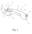
- FIG. 1 shown portable display device for haptic display of orientation information is equipped with a housing 1 and a probe element 2.
- the probe element 2 is adjustable relative to the housing 1, wherein a drive assembly 3 is provided for the motorized adjustment of the probe element 2.
- the arrangement is such that a motorized adjustment of the probe element 2 can be felt and thereby an orientation information can be displayed haptically.
- the probe element 2 for the haptic display of orientation information can be pivoted relative to the housing 1 by means of the drive arrangement 3.
- the probe element 2 is pivotable about a vertical axis 4 by means of the drive arrangement 3.
- the pivoting of the probe element 2 about the vertical axis 4 of the haptic display of direction information is used.
- the probe element 2 by means of the drive assembly 3 about a transverse axis 5 is pivotable.
- the pivoting of the probe element 2 about the transverse axis 5 preferably serves the haptic display of collision and / or surface information. In the illustrated embodiment, both a pivoting of the probe element 2 about the vertical axis 4 and a pivoting of the probe element 2 about the transverse axis 5 is provided.
- the vertical axis 4 is substantially vertically aligned in use and the transverse axis 5 is aligned substantially horizontally in use.
- the transverse axis 5 is preferably aligned perpendicular to the direction of movement of the user. This results in a particularly intuitive display.
- the display of direction information then takes place in the manner of a compass needle.
- the pivoting of the probe element 2 about the transverse axis 5 is conceptually connected by the user with a surface inclination, whereby surface and collision information can advantageously be displayed.
- the probe element 2 additionally or alternatively by means of the drive assembly 3 is pivotable about a longitudinal axis.
- the longitudinal axis is preferably aligned substantially in the direction of movement of the user. This also makes it possible to indicate directions perpendicular to the direction of movement, that is to say parallel displacements with regard to the direction of movement of the user, which have no component in the direction of movement, which may be advantageous in evasive maneuvers.
- a structurally particularly simple embodiment results from the fact that the probe element 2 is pivotally mounted in a first bearing 6 about the vertical axis 4 and that the first bearing 6 is pivotally mounted in a second bearing 7 about the transverse axis 5. This "nesting" of the two bearings 6, 7 leads to a particularly compact arrangement, such as Fig. 2 can be seen.
- a first drive motor 6a for the motorized pivoting of the probe element 2 about the vertical axis 4 and a second drive motor 7a for the pivoting of the probe element 2 about the transverse axis 5 is provided.
- the drive motors 6a, 7a may be rotary electric motors, solenoids or the like.
- the first drive motor 6a drives a pinion 6b which is directly connected to the feeler element 2.
- the probe element 2 and the first drive motor 6a are located on a carrier 7 mounted in the second bearing, which is connected to a pinion 7b.
- the pinion 7b is in drive connection with the second drive motor 7a.
- the storage of the above part spherical probe element 2 can also be done in other ways, for example by appropriately arranged bearing balls o. The like .. It is essential in such a configuration ultimately only the fact that the probe element 2 is partly spherical.
- the probe element 2 has a preferably continuous sensing surface 8. This means that the tactile surface 8 per se preferably has no tactile edges or the like. In a preferred embodiment, it is provided here that a feeler body 9 which can be felt on the touch surface 8 is arranged on the touch surface 8.
- the probe 9 allows a clear haptic display of the adjustment of the probe element 2.
- the probe 9 is designed as a survey on the touch surface 8 or as a depression in the touch surface 8. Other variants for the design of the probe 9 are given below.
- Fig. 1 It can be the representation in Fig. 1 can be seen that the vertical axis 4 extends through the touch surface 8 and is aligned substantially perpendicular to the touch surface 8 here. This is particularly advantageous with regard to an intuitive haptic display of the orientation information.
- Fig. 1 it is the representation in Fig. 1 Furthermore, it can be seen that the touch surface 8 is connected substantially directly to the housing 1, wherein the touch surface 8 is arranged here within a recess of the housing 1. A subjectively particularly pleasant impression can be achieved in that the transition from the touch surface 8 to the housing 1 is substantially continuous.
- the design of the touch surface 8 is important.
- the substantially convex configuration of the sensing surface 8 and preferably of the adjacent housing portion may be, for example, the surface of a sphere.
- the touch surface 8 and the adjacent housing portion may also be configured complementary to one another in such a way that the touch surface 8 is convex and the adjacent housing portion is concave or vice versa.
- the probe element 2 is designed around the vertical axis 4 on the one hand and about the transverse axis 5 on the other hand pivotally.
- the touch body 9 for haptic display of orientation information by means of the drive assembly 3 relative to the touch surface 8, preferably perpendicular to the touch surface 8, is adjustable. It is conceivable that the probe body 9 is pivotable perpendicular to the touch surface 8. Because a relative movement between the touch surface 8 and the touch body 9 is realized here, the touch body 9 effectively assumes the function of a forward or upward arrow o. The like. This can further improve the intuitive display of orientation information.
- the probe body 9 is designed to be elongated and is arranged radially with respect to the vertical axis 4.
- the oblong configuration of the feeler body 9 enhances the subjective impression that the feeler 9 is an arrow or the like.
- the probe body 9 is arranged with respect to the pivotability about the vertical axis 4 outside of the probe element 2. This further improves the quality of the display of orientation information.
- the probe body 9 extends from the vertical axis 4 to the outer edge of the probe element 2. However, it may also be provided that the probe body 9 passes through the vertical axis 4. In principle, it is also conceivable that the probe body 9 extends substantially over the entire width of the sensing surface 8.
- the shape of the probe 9 is of particular importance for the quality of the display.
- the probe body 9 is designed tapering in cross section in the direction of the vertical axis. This results in a tactile edge, which extends along the longitudinal extent of the elongate probe body 9. This is at the in Fig. 1 illustrated embodiment of the case.
- the feeler body 9 is designed to be rounded in cross-section or that the feeler body 9 is quadrangular when viewed in cross-section. Experiments with test persons have shown that an angular, in particular the pointed design of the feeler body leads to particularly good results in the display of orientation information.
- a particularly convenient embodiment results from the fact that the touch surface 8 has a groove-like shape which extends in the radial direction substantially with respect to the vertical axis 4 and is adapted to the shape of a human finger, that the finger can be positioned substantially positively in the groove-like shape is.
- the human finger then effectively blocks the pivoting of the probe element 2.
- the resulting force action of the probe element 2 on the human finger makes it possible a comfortable and at the same time intuitive display of the desired orientation information.
- the optimal configuration of the probe element 2 depends essentially on the subjective perception of the user. Therefore, numerous different implementation options for the probe element 2 are conceivable. Accordingly, it is advantageous if the display device is designed so far modular, that different sensing elements 2 can be used. It is preferably provided that the exchange with a few simple steps by the use of snap connections o. The like. In principle, a separate replacement of the probe body 9 may be provided.
- the housing 1 is designed as a one-handed handle, wherein the housing 1 is designed substantially elongated and can be grasped by a human hand.
- the housing 1 here has a shape that can commonly be referred to as bone-like.
- the display device can be fastened to a further component, for example to a wheelchair or the like.
- the thumb of the human hand is particularly suitable for recording haptic information. Therefore, it is provided in a preferred embodiment that in use the probe element 2 with the thumb of the housing 1 cross-hand is palpable.
- a scroll wheel 9a is provided, which is arranged in the immediate vicinity of the index finger of the housing 1 cross-hand and actuated by this.
- the portable display device can provide numerous other functions in addition to the haptic display of orientation information.
- a camera 11 is arranged, the signals of which can be displayed after appropriate processing via the probe element 2.
- the camera 11 is disposed within the housing 1, wherein the Housing 1 according to a transparent portion 12 has.
- a switch arrangement 14 is arranged, which can serve, for example, the selection of sensor functions or the like.
- the haptic display of orientation functions via the probe element 2 is essentially dependent on the position in which the portable display device is located in each case. To determine this position, it is provided that a preferably electronic compass 16 or a gyrocompass 16 is preferably arranged in the middle region 15 of the housing 1.
- a preferably electronic compass 16 or a gyrocompass 16 is preferably arranged in the middle region 15 of the housing 1.
- tilt sensors or the like can be used here.
- the housing 1 at the preferably front end 10 has a connecting piece 17 for a probe stick 18.
- the representation in Fig. 2 can be found in a preferred embodiment, the basic structure of the portable display device.
- the housing 1 is designed essentially in two parts here. In the central area next to the compass 16 and the power supply in the form of batteries 19 is arranged. Due to the bone-like design of the housing 1, the above-described additional components can be arranged at the front end 10 and at the rear end 13.
- the illustrated structure of the portable display device leads to a high degree of compactness and at the same time to low implementation costs due to the low number of parts.
- a power generator arrangement may be provided.
- An example of this is a dynamo that is driven by a crank.
- Another example is the conversion of the body heat of the user by corresponding electronic components. Conceivable here is the use of kinetic energy, which arises during the movement of the display device.
- the display device according to the invention is adaptable to the capabilities and characteristics of the user. This relates in particular to the adjustment characteristic of the probe element 2. For example, the adjustment speed of the probe element 2 and its maximum deflection can be configured differently.
- data for example map data or learned-in data
- the display device according to the invention is preferably equipped with an infrared interface or the like.
- the probe element 2 can also be used for input, and not just for the display of information. But is particularly easy to implement is an embodiment in which the probe element 2 is used only to display information and not the input of information.
- the feeler element 2 can be adjusted manually by the user and that a sensor arrangement is provided for detecting a manual, user-guided adjustment of the probe element 2.
- a manual pivoting of the probe element 2 can then be sensory capture. This can be advantageous in the case of the master-slave arrangement described below.
- One display device is referred to as a master device, while the other display device is called a slave device. It is so that the probe element 2 of the slave device can be adjusted by a manual, user-guided adjustment of the probe element 2 of the master device by motor.
- the master device thus serves as an input device.
- the slave device is remotely controlled by the master device.
- a visually impaired person can be equipped with the slave device and, so to speak, remotely controlled via the master device.
- the master device is operated accordingly by a non-visually impaired person. Expensive sensors can be completely omitted here. This kind of "Remote control" may also be advantageous for all other conceivable applications for the above display device.
- the master device can be a display device described above, which additionally serves to input orientation information.
- the master device and the slave device are of identical construction.
- a switch o. The like. Provide, with which it can be determined whether it is the respective device is the master device or the slave device.
- the possibility exists that the visually impaired person can also make inputs via the slave element via the slave device in order to give the non-visually impaired person specific feedback.
- the master device can also be a device which exclusively serves for the input of orientation information. A drive arrangement is then not provided in the master device, resulting in particularly low costs.
- the probe element 2 of the slave device can be remotely controlled motorized by a manual, user-guided adjustment of the probe element 2 of the master device. If the visually impaired person is to be guided to the left, for example, the person with no visual impairment pivots the feeler element 2 on the master device to the left, which subsequently leads to a corresponding pivoting of the feeler element 2 of the slave device to the left.
- This haptic display is registered by the visually impaired person so that they can change their direction of movement accordingly to the left.
- This remote control is preferably a wireless remote control based, for example, on radio, infrared or the like.
- the master device and the slave device each have a communication arrangement with which a data connection between the two devices can be established.
- a manual user-guided adjustment of the probe element 2 of the master device is detected by the sensor element associated with the probe element 2 and transmitted via the communication device to the slave device.
- the feeler element 2 of the slave device is adjusted accordingly by means of the associated drive arrangement 3, so that the input orientation information on the slave device is displayed haptically. It is preferably such that an adjustment of the probe element 2 on the master device leads to an identical adjustment of the probe element 2 on the slave device. However, it is also conceivable that different sensitivities can be set here.
- the motorized pivoting of the probe element 2 about the vertical axis 4 is associated with a direction information, wherein the motorized pivoting of the probe element 2 is preferably assigned to the transverse axis of a collision and / or surface information.
- a navigation module is preferably provided, direction information from the navigation module via the motorized pivoting of the probe element 2 about the vertical axis 4 can be issued.
- a collision avoidance module may be provided, wherein collision and surface information from the collision avoidance module about the motorized pivoting of the probe element 2 about the transverse axis 5 can be issued.
- the haptic display on the probe element 2 described above can be supplemented by other displays such as voice output, sound output o. The like. It can also be provided that the motorized adjustment of the probe element 2 is pulse-like, which also provides additional information on the pulse shape and length the user can be delivered. If there is a risk of collision, it may be provided that the pivoting of the probe element 2 about the transverse axis in short - and thus alarming - pulses is performed. In a further preferred embodiment, such additional information is displayed by the Verstellgeschwingtechnik and / or the adjustment of the probe element 2. This allows the desired information to be displayed steplessly and thus very precisely. It is also conceivable that the display device is equipped with a vibration generator to deliver this additional information to the user.
- the probe element 2 of the slave device can be remotely controlled by a manual, user-guided adjustment of the probe element 2 of the master device by motor.
- the probe element 2 of the two devices can as described above, but need not be adjustable in several degrees of freedom. It is conceivable pivotability of the probe elements 2 for haptic display or input direction information exclusively about a vertical axis 4.
- the design of the master device and the slave device may be made to the full extent to the above statements.
- the portable display device according to the invention is suitable for the assistance of visually impaired persons. This applies in particular if the visually impaired person additionally has only limited hearing. Basically, however, the portable display device is applicable to any field where there is insufficient visual information. As an example, the support of firefighters was called at high smoke. Other examples are the support of divers, sailors or pilots, when insufficient visibility prevails.
- the display device can also serve as a display device for a personal computer or the like, for example as part of the preparation of a visually impaired person for the route to be run or in the context of a computer game.
- the inventive portable display device can thus be coupled with any devices that provide orientation information of any kind.
- the display device according to the invention is preferably an add-on component, for example for GPS navigation systems or the like.
- the above display device, the mobility aid and the Mobility Assistance Arrangement are also referred to as the Personal Travel Assistant (PETRA).
Landscapes
- Health & Medical Sciences (AREA)
- General Health & Medical Sciences (AREA)
- Epidemiology (AREA)
- Pain & Pain Management (AREA)
- Physical Education & Sports Medicine (AREA)
- Rehabilitation Therapy (AREA)
- Life Sciences & Earth Sciences (AREA)
- Animal Behavior & Ethology (AREA)
- Public Health (AREA)
- Veterinary Medicine (AREA)
- Engineering & Computer Science (AREA)
- Physics & Mathematics (AREA)
- Business, Economics & Management (AREA)
- Audiology, Speech & Language Pathology (AREA)
- Educational Administration (AREA)
- Educational Technology (AREA)
- General Physics & Mathematics (AREA)
- Theoretical Computer Science (AREA)
- User Interface Of Digital Computer (AREA)
- Navigation (AREA)
- Measurement And Recording Of Electrical Phenomena And Electrical Characteristics Of The Living Body (AREA)
- Compositions Of Oxide Ceramics (AREA)
- Devices For Indicating Variable Information By Combining Individual Elements (AREA)
- Fittings On The Vehicle Exterior For Carrying Loads, And Devices For Holding Or Mounting Articles (AREA)
Applications Claiming Priority (2)
| Application Number | Priority Date | Filing Date | Title |
|---|---|---|---|
| DE202006000980U DE202006000980U1 (de) | 2006-01-20 | 2006-01-20 | Tragbares Anzeigegerät zur haptischen Anzeige von Orientierungsinformationen |
| EP07001130A EP1813244B1 (fr) | 2006-01-20 | 2007-01-19 | Appareil de signalisation portatif destiné à la signalisation haptique d'informations d'orientation |
Related Parent Applications (2)
| Application Number | Title | Priority Date | Filing Date |
|---|---|---|---|
| EP07001130A Division EP1813244B1 (fr) | 2006-01-20 | 2007-01-19 | Appareil de signalisation portatif destiné à la signalisation haptique d'informations d'orientation |
| EP07001130.9 Division | 2007-01-19 |
Publications (2)
| Publication Number | Publication Date |
|---|---|
| EP2074980A1 true EP2074980A1 (fr) | 2009-07-01 |
| EP2074980B1 EP2074980B1 (fr) | 2013-03-27 |
Family
ID=37903947
Family Applications (2)
| Application Number | Title | Priority Date | Filing Date |
|---|---|---|---|
| EP07001130A Not-in-force EP1813244B1 (fr) | 2006-01-20 | 2007-01-19 | Appareil de signalisation portatif destiné à la signalisation haptique d'informations d'orientation |
| EP09004658A Not-in-force EP2074980B1 (fr) | 2006-01-20 | 2007-01-19 | Dispositif d'aide à la mobilité |
Family Applications Before (1)
| Application Number | Title | Priority Date | Filing Date |
|---|---|---|---|
| EP07001130A Not-in-force EP1813244B1 (fr) | 2006-01-20 | 2007-01-19 | Appareil de signalisation portatif destiné à la signalisation haptique d'informations d'orientation |
Country Status (5)
| Country | Link |
|---|---|
| EP (2) | EP1813244B1 (fr) |
| AT (1) | ATE427093T1 (fr) |
| DE (2) | DE202006000980U1 (fr) |
| DK (2) | DK2074980T3 (fr) |
| ES (2) | ES2324838T3 (fr) |
Families Citing this family (8)
| Publication number | Priority date | Publication date | Assignee | Title |
|---|---|---|---|---|
| DE102010046291B4 (de) * | 2010-09-22 | 2016-03-10 | Aissa Zouhri | Orientierungshilfevorrichtung |
| JP5486481B2 (ja) * | 2010-12-06 | 2014-05-07 | パナソニック株式会社 | 頭皮ケア装置 |
| DE102012008784A1 (de) | 2012-05-07 | 2013-11-07 | I-Cane Social Technology Bv | Haptische Benutzerschnittstelle |
| DE102013016944A1 (de) | 2013-10-14 | 2015-04-16 | I-Cane Social Technology Bv | Assistenzsystem |
| IN2014DE00388A (fr) * | 2014-02-12 | 2015-08-14 | Indian Inst Technology Delhi | |
| CN107913159A (zh) * | 2017-11-22 | 2018-04-17 | 佛山市海科云筹信息技术有限公司 | 一种通过红外信号准确指示方位的盲杖及方法 |
| CN107789167A (zh) * | 2017-11-22 | 2018-03-13 | 佛山市海科云筹信息技术有限公司 | 一种能帮助视障人士准确指示方位的盲杖及方法 |
| CN119345004B (zh) * | 2024-10-28 | 2026-04-24 | 广州大学 | 一种智能交互系统及智能导盲拐杖 |
Citations (6)
| Publication number | Priority date | Publication date | Assignee | Title |
|---|---|---|---|---|
| US3736551A (en) | 1970-11-16 | 1973-05-29 | Us Navy | Swimmers tactile command navigation apparatus |
| US5047952A (en) | 1988-10-14 | 1991-09-10 | The Board Of Trustee Of The Leland Stanford Junior University | Communication system for deaf, deaf-blind, or non-vocal individuals using instrumented glove |
| DE19517649A1 (de) | 1995-05-17 | 1996-11-21 | Thomas Rupp | Vorrichtung zum Übermitteln von Zeichen und Buchstaben von einer Datenverarbeitungsanlage an eine taubblinde Person |
| WO1997015265A1 (fr) | 1995-10-25 | 1997-05-01 | Techn-O-Tape B.V. | Canne blanche pour malvoyants |
| GB2320315A (en) | 1996-12-14 | 1998-06-17 | Heping He | A keyboard glove for use by the blind |
| DE102004042884A1 (de) | 2004-09-04 | 2006-03-23 | Hönicke, Bernd | Kommunikationsgerät für taubblinde Personen |
Family Cites Families (3)
| Publication number | Priority date | Publication date | Assignee | Title |
|---|---|---|---|---|
| DE589531C (de) * | 1932-11-08 | 1933-12-13 | Fritz Kreis | Blindenkompass |
| ES2212314T3 (es) * | 1997-04-30 | 2004-07-16 | Maria Ritz | Aparato para ayuda de orientacion para deficientes visuales. |
| DE20214852U1 (de) * | 2002-09-09 | 2003-02-13 | Kaphahn, Alexandra, Dipl.-Ing., 52072 Aachen | Tragbare Mobilitätshilfe für sehbehinderte Personen |
-
2006
- 2006-01-20 DE DE202006000980U patent/DE202006000980U1/de not_active Expired - Lifetime
-
2007
- 2007-01-19 ES ES07001130T patent/ES2324838T3/es active Active
- 2007-01-19 EP EP07001130A patent/EP1813244B1/fr not_active Not-in-force
- 2007-01-19 EP EP09004658A patent/EP2074980B1/fr not_active Not-in-force
- 2007-01-19 ES ES09004658T patent/ES2412431T3/es active Active
- 2007-01-19 DE DE502007000543T patent/DE502007000543D1/de active Active
- 2007-01-19 DK DK09004658.2T patent/DK2074980T3/da active
- 2007-01-19 DK DK07001130T patent/DK1813244T3/da active
- 2007-01-19 AT AT07001130T patent/ATE427093T1/de active
Patent Citations (6)
| Publication number | Priority date | Publication date | Assignee | Title |
|---|---|---|---|---|
| US3736551A (en) | 1970-11-16 | 1973-05-29 | Us Navy | Swimmers tactile command navigation apparatus |
| US5047952A (en) | 1988-10-14 | 1991-09-10 | The Board Of Trustee Of The Leland Stanford Junior University | Communication system for deaf, deaf-blind, or non-vocal individuals using instrumented glove |
| DE19517649A1 (de) | 1995-05-17 | 1996-11-21 | Thomas Rupp | Vorrichtung zum Übermitteln von Zeichen und Buchstaben von einer Datenverarbeitungsanlage an eine taubblinde Person |
| WO1997015265A1 (fr) | 1995-10-25 | 1997-05-01 | Techn-O-Tape B.V. | Canne blanche pour malvoyants |
| GB2320315A (en) | 1996-12-14 | 1998-06-17 | Heping He | A keyboard glove for use by the blind |
| DE102004042884A1 (de) | 2004-09-04 | 2006-03-23 | Hönicke, Bernd | Kommunikationsgerät für taubblinde Personen |
Non-Patent Citations (1)
| Title |
|---|
| "Hauptkatalog 2005/2006", 2005, CONRAD ELECTRONIC GMBH, XP002440409 * |
Also Published As
| Publication number | Publication date |
|---|---|
| EP1813244A3 (fr) | 2007-09-05 |
| DE202006000980U1 (de) | 2007-05-24 |
| DK1813244T3 (da) | 2009-07-06 |
| ATE427093T1 (de) | 2009-04-15 |
| ES2412431T3 (es) | 2013-07-11 |
| DE502007000543D1 (de) | 2009-05-14 |
| EP1813244A2 (fr) | 2007-08-01 |
| EP2074980B1 (fr) | 2013-03-27 |
| ES2324838T3 (es) | 2009-08-17 |
| EP1813244B1 (fr) | 2009-04-01 |
| DK2074980T3 (da) | 2013-07-01 |
Similar Documents
| Publication | Publication Date | Title |
|---|---|---|
| EP2074980B1 (fr) | Dispositif d'aide à la mobilité | |
| DE69816319T2 (de) | Multischaltereinrichtung für die steurung von fahrzeugsubsystemen | |
| CH660554A5 (de) | Einrichtung zum ansteuern eines elektrisch betriebenen apparates. | |
| DE102005009110A1 (de) | Vorrichtung zur Vermittlung von Umgebungsinformationen an einen sehbehinderten Menschen | |
| DE2401366A1 (de) | Anzeigesystem mit positionsindikator | |
| DE69814713T2 (de) | Eingabevorrichtung zur Verbesserung einer Mensch-Maschine-Schnittstelle | |
| AT520408B1 (de) | Fernsteuerung für Kameras | |
| EP1518725A2 (fr) | Dispositif et procédé pour le réglage de valeurs de consigne d'un système de conditionnement d'air pour véhicule | |
| DE102005014939A1 (de) | Bedienelement und Schnittstelle für Fahrzeugrechner | |
| DE102018207734B4 (de) | Rückmeldeeinrichtung für ein Kraftfahrzeug, Kraftfahrzeug und Verfahren zum Ausgeben einer Rückmeldung | |
| DE1803195A1 (de) | Visuelles Lehrgeraet | |
| AT412745B (de) | Steuereinheit | |
| DE102007057924B4 (de) | Verfahren für eine blindengerechte Benutzerschnittstelle zur Navigation und Kontrolle von Computern oder elektronisch- bzw. computergesteuerten Geräten | |
| DE102008028365A1 (de) | Rotorfluggerät mit einer Steuereinrichtung zum Generieren von Steuerbefehlen | |
| EP3960594A1 (fr) | Procédé de fonctionnement d'un entraînement auxiliaire pour une remorque, système d'entraînement d'au moins une roue d'une telle remorque, ainsi que produit-programme informatique et support de données permettant de mettre en uvre les étapes du procédé | |
| DE102007038755A1 (de) | Sport-, Therapie- oder Spielgerät | |
| DE102020123568B3 (de) | Kommunikationswerkzeug | |
| DE102010048504B3 (de) | Gebetshilfevorrichtung | |
| DE10357774A1 (de) | Eingabevorrichtung | |
| EP3231486A1 (fr) | Appareil de therapie, systeme de therapie et son utilisation et procede d'identification d'un objet | |
| DE102004048888B4 (de) | Bedieneinrichtung | |
| DE3606439A1 (de) | Verfahren und einrichtung zum manuellen fuehren eines roboters | |
| DE202010014301U1 (de) | Gebetshilfevorrichtung | |
| DE102007045151A1 (de) | Vorrichtung zur Messung von medizinischen Parametern des menschlichen Körpers | |
| DE10043566B4 (de) | Trainingsgerät für Bewegungsbehinderte |
Legal Events
| Date | Code | Title | Description |
|---|---|---|---|
| PUAI | Public reference made under article 153(3) epc to a published international application that has entered the european phase |
Free format text: ORIGINAL CODE: 0009012 |
|
| AC | Divisional application: reference to earlier application |
Ref document number: 1813244 Country of ref document: EP Kind code of ref document: P |
|
| AK | Designated contracting states |
Kind code of ref document: A1 Designated state(s): AT BE BG CH CY CZ DE DK EE ES FI FR GB GR HU IE IS IT LI LT LU LV MC NL PL PT RO SE SI SK TR |
|
| RAP3 | Party data changed (applicant data changed or rights of an application transferred) |
Owner name: STICHTING ONTWIKKELING EN VERVAARDIGING VAN HULPMI |
|
| 17P | Request for examination filed |
Effective date: 20091222 |
|
| 17Q | First examination report despatched |
Effective date: 20100125 |
|
| AKX | Designation fees paid |
Designated state(s): AT BE BG CH CY CZ DE DK EE ES FI FR GB GR HU IE IS IT LI LT LU LV MC NL PL PT RO SE SI SK TR |
|
| RIC1 | Information provided on ipc code assigned before grant |
Ipc: G09B 21/00 20060101ALI20120830BHEP Ipc: A61H 3/06 20060101AFI20120830BHEP |
|
| GRAP | Despatch of communication of intention to grant a patent |
Free format text: ORIGINAL CODE: EPIDOSNIGR1 |
|
| GRAS | Grant fee paid |
Free format text: ORIGINAL CODE: EPIDOSNIGR3 |
|
| GRAA | (expected) grant |
Free format text: ORIGINAL CODE: 0009210 |
|
| AC | Divisional application: reference to earlier application |
Ref document number: 1813244 Country of ref document: EP Kind code of ref document: P |
|
| AK | Designated contracting states |
Kind code of ref document: B1 Designated state(s): AT BE BG CH CY CZ DE DK EE ES FI FR GB GR HU IE IS IT LI LT LU LV MC NL PL PT RO SE SI SK TR |
|
| REG | Reference to a national code |
Ref country code: GB Ref legal event code: FG4D Free format text: NOT ENGLISH |
|
| REG | Reference to a national code |
Ref country code: CH Ref legal event code: EP |
|
| REG | Reference to a national code |
Ref country code: AT Ref legal event code: REF Ref document number: 602898 Country of ref document: AT Kind code of ref document: T Effective date: 20130415 |
|
| REG | Reference to a national code |
Ref country code: IE Ref legal event code: FG4D Free format text: LANGUAGE OF EP DOCUMENT: GERMAN |
|
| REG | Reference to a national code |
Ref country code: DE Ref legal event code: R096 Ref document number: 502007011534 Country of ref document: DE Effective date: 20130523 |
|
| REG | Reference to a national code |
Ref country code: DK Ref legal event code: T3 |
|
| REG | Reference to a national code |
Ref country code: ES Ref legal event code: FG2A Ref document number: 2412431 Country of ref document: ES Kind code of ref document: T3 Effective date: 20130711 |
|
| REG | Reference to a national code |
Ref country code: SE Ref legal event code: TRGR |
|
| PG25 | Lapsed in a contracting state [announced via postgrant information from national office to epo] |
Ref country code: LT Free format text: LAPSE BECAUSE OF FAILURE TO SUBMIT A TRANSLATION OF THE DESCRIPTION OR TO PAY THE FEE WITHIN THE PRESCRIBED TIME-LIMIT Effective date: 20130327 Ref country code: BG Free format text: LAPSE BECAUSE OF FAILURE TO SUBMIT A TRANSLATION OF THE DESCRIPTION OR TO PAY THE FEE WITHIN THE PRESCRIBED TIME-LIMIT Effective date: 20130627 |
|
| REG | Reference to a national code |
Ref country code: LT Ref legal event code: MG4D |
|
| REG | Reference to a national code |
Ref country code: NL Ref legal event code: T3 |
|
| PG25 | Lapsed in a contracting state [announced via postgrant information from national office to epo] |
Ref country code: GR Free format text: LAPSE BECAUSE OF FAILURE TO SUBMIT A TRANSLATION OF THE DESCRIPTION OR TO PAY THE FEE WITHIN THE PRESCRIBED TIME-LIMIT Effective date: 20130628 Ref country code: LV Free format text: LAPSE BECAUSE OF FAILURE TO SUBMIT A TRANSLATION OF THE DESCRIPTION OR TO PAY THE FEE WITHIN THE PRESCRIBED TIME-LIMIT Effective date: 20130327 Ref country code: SI Free format text: LAPSE BECAUSE OF FAILURE TO SUBMIT A TRANSLATION OF THE DESCRIPTION OR TO PAY THE FEE WITHIN THE PRESCRIBED TIME-LIMIT Effective date: 20130327 |
|
| PG25 | Lapsed in a contracting state [announced via postgrant information from national office to epo] |
Ref country code: CZ Free format text: LAPSE BECAUSE OF FAILURE TO SUBMIT A TRANSLATION OF THE DESCRIPTION OR TO PAY THE FEE WITHIN THE PRESCRIBED TIME-LIMIT Effective date: 20130327 Ref country code: EE Free format text: LAPSE BECAUSE OF FAILURE TO SUBMIT A TRANSLATION OF THE DESCRIPTION OR TO PAY THE FEE WITHIN THE PRESCRIBED TIME-LIMIT Effective date: 20130327 Ref country code: SK Free format text: LAPSE BECAUSE OF FAILURE TO SUBMIT A TRANSLATION OF THE DESCRIPTION OR TO PAY THE FEE WITHIN THE PRESCRIBED TIME-LIMIT Effective date: 20130327 Ref country code: RO Free format text: LAPSE BECAUSE OF FAILURE TO SUBMIT A TRANSLATION OF THE DESCRIPTION OR TO PAY THE FEE WITHIN THE PRESCRIBED TIME-LIMIT Effective date: 20130327 Ref country code: IS Free format text: LAPSE BECAUSE OF FAILURE TO SUBMIT A TRANSLATION OF THE DESCRIPTION OR TO PAY THE FEE WITHIN THE PRESCRIBED TIME-LIMIT Effective date: 20130727 Ref country code: PT Free format text: LAPSE BECAUSE OF FAILURE TO SUBMIT A TRANSLATION OF THE DESCRIPTION OR TO PAY THE FEE WITHIN THE PRESCRIBED TIME-LIMIT Effective date: 20130729 |
|
| PG25 | Lapsed in a contracting state [announced via postgrant information from national office to epo] |
Ref country code: PL Free format text: LAPSE BECAUSE OF FAILURE TO SUBMIT A TRANSLATION OF THE DESCRIPTION OR TO PAY THE FEE WITHIN THE PRESCRIBED TIME-LIMIT Effective date: 20130327 Ref country code: CY Free format text: LAPSE BECAUSE OF FAILURE TO SUBMIT A TRANSLATION OF THE DESCRIPTION OR TO PAY THE FEE WITHIN THE PRESCRIBED TIME-LIMIT Effective date: 20130327 |
|
| PLBE | No opposition filed within time limit |
Free format text: ORIGINAL CODE: 0009261 |
|
| STAA | Information on the status of an ep patent application or granted ep patent |
Free format text: STATUS: NO OPPOSITION FILED WITHIN TIME LIMIT |
|
| PG25 | Lapsed in a contracting state [announced via postgrant information from national office to epo] |
Ref country code: IT Free format text: LAPSE BECAUSE OF FAILURE TO SUBMIT A TRANSLATION OF THE DESCRIPTION OR TO PAY THE FEE WITHIN THE PRESCRIBED TIME-LIMIT Effective date: 20130327 |
|
| PGFP | Annual fee paid to national office [announced via postgrant information from national office to epo] |
Ref country code: LU Payment date: 20140123 Year of fee payment: 8 |
|
| 26N | No opposition filed |
Effective date: 20140103 |
|
| REG | Reference to a national code |
Ref country code: DE Ref legal event code: R097 Ref document number: 502007011534 Country of ref document: DE Effective date: 20140103 |
|
| PGFP | Annual fee paid to national office [announced via postgrant information from national office to epo] |
Ref country code: CH Payment date: 20140121 Year of fee payment: 8 Ref country code: DK Payment date: 20140121 Year of fee payment: 8 Ref country code: NL Payment date: 20140121 Year of fee payment: 8 Ref country code: SE Payment date: 20140121 Year of fee payment: 8 Ref country code: FI Payment date: 20140113 Year of fee payment: 8 Ref country code: BE Payment date: 20140121 Year of fee payment: 8 Ref country code: DE Payment date: 20140121 Year of fee payment: 8 |
|
| PGFP | Annual fee paid to national office [announced via postgrant information from national office to epo] |
Ref country code: AT Payment date: 20140113 Year of fee payment: 8 Ref country code: ES Payment date: 20140129 Year of fee payment: 8 Ref country code: FR Payment date: 20140123 Year of fee payment: 8 |
|
| PGFP | Annual fee paid to national office [announced via postgrant information from national office to epo] |
Ref country code: GB Payment date: 20140121 Year of fee payment: 8 |
|
| PG25 | Lapsed in a contracting state [announced via postgrant information from national office to epo] |
Ref country code: MC Free format text: LAPSE BECAUSE OF FAILURE TO SUBMIT A TRANSLATION OF THE DESCRIPTION OR TO PAY THE FEE WITHIN THE PRESCRIBED TIME-LIMIT Effective date: 20130327 |
|
| REG | Reference to a national code |
Ref country code: IE Ref legal event code: MM4A |
|
| PG25 | Lapsed in a contracting state [announced via postgrant information from national office to epo] |
Ref country code: IE Free format text: LAPSE BECAUSE OF NON-PAYMENT OF DUE FEES Effective date: 20140119 |
|
| PG25 | Lapsed in a contracting state [announced via postgrant information from national office to epo] |
Ref country code: BE Free format text: LAPSE BECAUSE OF NON-PAYMENT OF DUE FEES Effective date: 20150131 |
|
| REG | Reference to a national code |
Ref country code: DE Ref legal event code: R119 Ref document number: 502007011534 Country of ref document: DE |
|
| REG | Reference to a national code |
Ref country code: NL Ref legal event code: V1 Effective date: 20150801 |
|
| REG | Reference to a national code |
Ref country code: CH Ref legal event code: PL |
|
| PG25 | Lapsed in a contracting state [announced via postgrant information from national office to epo] |
Ref country code: LU Free format text: LAPSE BECAUSE OF NON-PAYMENT OF DUE FEES Effective date: 20150119 |
|
| REG | Reference to a national code |
Ref country code: DK Ref legal event code: EBP Effective date: 20150131 |
|
| REG | Reference to a national code |
Ref country code: SE Ref legal event code: EUG |
|
| REG | Reference to a national code |
Ref country code: AT Ref legal event code: MM01 Ref document number: 602898 Country of ref document: AT Kind code of ref document: T Effective date: 20150119 |
|
| GBPC | Gb: european patent ceased through non-payment of renewal fee |
Effective date: 20150119 |
|
| PG25 | Lapsed in a contracting state [announced via postgrant information from national office to epo] |
Ref country code: NL Free format text: LAPSE BECAUSE OF NON-PAYMENT OF DUE FEES Effective date: 20150801 |
|
| PG25 | Lapsed in a contracting state [announced via postgrant information from national office to epo] |
Ref country code: FI Free format text: LAPSE BECAUSE OF NON-PAYMENT OF DUE FEES Effective date: 20150119 Ref country code: GB Free format text: LAPSE BECAUSE OF NON-PAYMENT OF DUE FEES Effective date: 20150119 Ref country code: DE Free format text: LAPSE BECAUSE OF NON-PAYMENT OF DUE FEES Effective date: 20150801 Ref country code: CH Free format text: LAPSE BECAUSE OF NON-PAYMENT OF DUE FEES Effective date: 20150131 Ref country code: LI Free format text: LAPSE BECAUSE OF NON-PAYMENT OF DUE FEES Effective date: 20150131 |
|
| REG | Reference to a national code |
Ref country code: FR Ref legal event code: ST Effective date: 20150930 |
|
| PG25 | Lapsed in a contracting state [announced via postgrant information from national office to epo] |
Ref country code: FR Free format text: LAPSE BECAUSE OF NON-PAYMENT OF DUE FEES Effective date: 20150202 Ref country code: AT Free format text: LAPSE BECAUSE OF NON-PAYMENT OF DUE FEES Effective date: 20150119 Ref country code: SE Free format text: LAPSE BECAUSE OF NON-PAYMENT OF DUE FEES Effective date: 20150120 |
|
| PG25 | Lapsed in a contracting state [announced via postgrant information from national office to epo] |
Ref country code: DK Free format text: LAPSE BECAUSE OF NON-PAYMENT OF DUE FEES Effective date: 20150131 |
|
| REG | Reference to a national code |
Ref country code: ES Ref legal event code: FD2A Effective date: 20160226 |
|
| PG25 | Lapsed in a contracting state [announced via postgrant information from national office to epo] |
Ref country code: ES Free format text: LAPSE BECAUSE OF NON-PAYMENT OF DUE FEES Effective date: 20150120 |
|
| PG25 | Lapsed in a contracting state [announced via postgrant information from national office to epo] |
Ref country code: HU Free format text: LAPSE BECAUSE OF FAILURE TO SUBMIT A TRANSLATION OF THE DESCRIPTION OR TO PAY THE FEE WITHIN THE PRESCRIBED TIME-LIMIT; INVALID AB INITIO Effective date: 20070119 Ref country code: TR Free format text: LAPSE BECAUSE OF FAILURE TO SUBMIT A TRANSLATION OF THE DESCRIPTION OR TO PAY THE FEE WITHIN THE PRESCRIBED TIME-LIMIT Effective date: 20130327 |