EP2075112B1 - Luftreifenherstellungsverfahren und Luftreifen - Google Patents
Luftreifenherstellungsverfahren und Luftreifen Download PDFInfo
- Publication number
- EP2075112B1 EP2075112B1 EP08021067A EP08021067A EP2075112B1 EP 2075112 B1 EP2075112 B1 EP 2075112B1 EP 08021067 A EP08021067 A EP 08021067A EP 08021067 A EP08021067 A EP 08021067A EP 2075112 B1 EP2075112 B1 EP 2075112B1
- Authority
- EP
- European Patent Office
- Prior art keywords
- protective rubber
- rubber layer
- side fastener
- engagement element
- layer
- Prior art date
- Legal status (The legal status is an assumption and is not a legal conclusion. Google has not performed a legal analysis and makes no representation as to the accuracy of the status listed.)
- Ceased
Links
Images


Classifications
-
- B—PERFORMING OPERATIONS; TRANSPORTING
- B29—WORKING OF PLASTICS; WORKING OF SUBSTANCES IN A PLASTIC STATE IN GENERAL
- B29D—PRODUCING PARTICULAR ARTICLES FROM PLASTICS OR FROM SUBSTANCES IN A PLASTIC STATE
- B29D30/00—Producing pneumatic or solid tyres or parts thereof
- B29D30/06—Pneumatic tyres or parts thereof (e.g. produced by casting, moulding, compression moulding, injection moulding, centrifugal casting)
- B29D30/08—Building tyres
- B29D30/20—Building tyres by the flat-tyre method, i.e. building on cylindrical drums
-
- B—PERFORMING OPERATIONS; TRANSPORTING
- B29—WORKING OF PLASTICS; WORKING OF SUBSTANCES IN A PLASTIC STATE IN GENERAL
- B29D—PRODUCING PARTICULAR ARTICLES FROM PLASTICS OR FROM SUBSTANCES IN A PLASTIC STATE
- B29D30/00—Producing pneumatic or solid tyres or parts thereof
- B29D30/0061—Accessories, details or auxiliary operations not otherwise provided for
-
- B—PERFORMING OPERATIONS; TRANSPORTING
- B60—VEHICLES IN GENERAL
- B60C—VEHICLE TYRES; TYRE INFLATION; TYRE CHANGING; CONNECTING VALVES TO INFLATABLE ELASTIC BODIES IN GENERAL; DEVICES OR ARRANGEMENTS RELATED TO TYRES
- B60C19/00—Tyre parts or constructions not otherwise provided for
- B60C19/002—Noise damping elements provided in the tyre structure or attached thereto, e.g. in the tyre interior
-
- B—PERFORMING OPERATIONS; TRANSPORTING
- B29—WORKING OF PLASTICS; WORKING OF SUBSTANCES IN A PLASTIC STATE IN GENERAL
- B29D—PRODUCING PARTICULAR ARTICLES FROM PLASTICS OR FROM SUBSTANCES IN A PLASTIC STATE
- B29D30/00—Producing pneumatic or solid tyres or parts thereof
- B29D30/0061—Accessories, details or auxiliary operations not otherwise provided for
- B29D2030/0072—Attaching fasteners to tyres, e.g. patches, in order to connect devices to tyres
-
- B—PERFORMING OPERATIONS; TRANSPORTING
- B29—WORKING OF PLASTICS; WORKING OF SUBSTANCES IN A PLASTIC STATE IN GENERAL
- B29D—PRODUCING PARTICULAR ARTICLES FROM PLASTICS OR FROM SUBSTANCES IN A PLASTIC STATE
- B29D30/00—Producing pneumatic or solid tyres or parts thereof
- B29D30/06—Pneumatic tyres or parts thereof (e.g. produced by casting, moulding, compression moulding, injection moulding, centrifugal casting)
- B29D30/0601—Vulcanising tyres; Vulcanising presses for tyres
- B29D30/0633—After-treatment specially adapted for vulcanising tyres
- B29D2030/0634—Measuring, calculating, correcting tyre uniformity, e.g. correcting RFV
- B29D2030/0637—Correcting by adding material
-
- Y—GENERAL TAGGING OF NEW TECHNOLOGICAL DEVELOPMENTS; GENERAL TAGGING OF CROSS-SECTIONAL TECHNOLOGIES SPANNING OVER SEVERAL SECTIONS OF THE IPC; TECHNICAL SUBJECTS COVERED BY FORMER USPC CROSS-REFERENCE ART COLLECTIONS [XRACs] AND DIGESTS
- Y10—TECHNICAL SUBJECTS COVERED BY FORMER USPC
- Y10T—TECHNICAL SUBJECTS COVERED BY FORMER US CLASSIFICATION
- Y10T152/00—Resilient tires and wheels
- Y10T152/10—Tires, resilient
- Y10T152/10495—Pneumatic tire or inner tube
-
- Y—GENERAL TAGGING OF NEW TECHNOLOGICAL DEVELOPMENTS; GENERAL TAGGING OF CROSS-SECTIONAL TECHNOLOGIES SPANNING OVER SEVERAL SECTIONS OF THE IPC; TECHNICAL SUBJECTS COVERED BY FORMER USPC CROSS-REFERENCE ART COLLECTIONS [XRACs] AND DIGESTS
- Y10—TECHNICAL SUBJECTS COVERED BY FORMER USPC
- Y10T—TECHNICAL SUBJECTS COVERED BY FORMER US CLASSIFICATION
- Y10T152/00—Resilient tires and wheels
- Y10T152/10—Tires, resilient
- Y10T152/10495—Pneumatic tire or inner tube
- Y10T152/10855—Characterized by the carcass, carcass material, or physical arrangement of the carcass materials
Definitions
- the present invention relates to: a method of manufacturing a pneumatic tire having surface fasteners on its tire inner surface; and a pneumatic tire manufactured by the method.
- the present invention relates to a pneumatic tire manufacturing method which improves the productivity of pneumatic tires each having surface fasteners on its tire inner surface, and which avoids manufacturing a pneumatic tire having a deteriorated uniformity, as well as which prevents engagement elements of each surface fastener from being crushed.
- the present invention also relates to a pneumatic tire manufactured by the manufacturing method.
- noise absorbing materials are provided to the inner surface of the tire cavity for the purpose of reducing cavity resonance.
- the applicant of the present invention has made a proposal on a pneumatic tire having surface fasteners each made of a resin such as nylon or polyester on the tire inner surface so that such noise absorbing materials can be attached to the tire easily (see Japanese patent application Kokai publication No. 2006-44503 , for example).
- Surface fasteners capable of engaging with the surface fasteners provided to the tire inner surface are also attached to the noise absorbing materials.
- the surface fasteners attached to the noise absorbing materials are engaged with the surface fasteners provided to the tire inner surface, respectively. This engagement scheme enables the noise absorbing materials to be easily attached to and easily detached as needed from the tire inner surface.
- a pneumatic tire of the foregoing type having surface fasteners on the tire inner surface is produced by curing a formed green tire having the surface fasteners beforehand adhered to its inner surface.
- the pneumatic tire manufacturing method includes a step of deforming a first formed body into a toroidal shape by expansion, the first formed body having been obtained by beforehand adhering an inner liner layer, a carcass layer and the like together on a making drum.
- the surface fasteners each made of a resin such as nylon and polyester are annularly attached to the first formed body which has not yet been deformed by expansion, the surface fasteners can not follow the posterior deformation of the first formed body by expansion, thus falling off from the green tire, since the inner periphery length of the first formed body is extended to a large extent. For this reason, such surface fasteners are attached to the green tire after the first formed body is deformed into the toroidal shape by expansion.
- the surface fasteners need to be attached to the inner surface of the cavity of the green tire.
- the attachment requires meticulous work and results in a lower workability. This is a cause of decreasing the productivity.
- the surface fasteners are attached to the curved inner surface by hand. This manual work makes it difficult to attach the surface fasteners to the inner surface around an entire circuit of the tire evenly, and inevitably results in deteriorated uniformity.
- the green tire is cured in the mold while pressed from its inside by a bladder.
- engagement elements of each surface fastener which are exposed to the tire inner surface may be crushed by a pressing force of the bladder. For this reason, measures for this problem are required to be taken as well.
- US 2004/103 967 A1 discloses the use of a self-supporting barrier film during curing of a tire.
- Embodiments of the present invention are able to provide a pneumatic tire manufacturing method which improves the productivity of pneumatic tires each having surface fasteners on its tire inner surface, and which avoids manufacturing a pneumatic tire having a deteriorated uniformity, as well as which prevents engagement elements of each surface fastener from being crushed.
- Embodiments of the present invention are additionally able to provide a pneumatic tire manufactured by the manufacturing method.
- a pneumatic tire manufacturing method in making a green tire having two-side fasteners in its tire inner surface in its tire circumferential direction, each two-side fastener including an engagement element group on both sides, the method comprising the steps of: covering the engagement element groups on first sides of the two-side fasteners with a protective rubber layer made of an uncured rubber; making a cylindrical first formed body on a making drum, with the two-side fasteners covered with the protective rubber layer being intermittently attached to an inner circumferential surface of the first formed body in a circumferential direction thereof with the engagement element groups on second sides of the two-side fasteners being interposed in between; bonding the first formed body to an inner circumference of an annular second formed body by compression through expanding the first formed body into a toroidal shape, and thereby making the green tire; and curing the green tire inside a mold of a curing machine while pressing the green tire from its inside by a bladder.
- the pneumatic tire according to the present invention is characterized by being manufactured by the pneumatic tire manufacturing method according to any one of claims 1 to 13.
- Embodiments of the present invention are capable of avoiding falling off of the two-side fasteners from the inner circumferential surface of the first formed body while the first formed body is being deformed into the toroidal shape by expansion. That is because embodiments of the present invention described above cause the first formed body to be made by intermittently attaching the two-side fasteners to the inner circumferential surface of the first formed body. Thus, the intermittent portions of the first formed body between the neighboring two-side fasteners are allowed to be stretched by following the expanding deformation of the first formed body into the toroidal shape while not obstructed by the two-side fasteners, when the first formed body is thus deformed.
- embodiments of the present invention make it possible to attach the two-side fasteners to the inner circumferential surface of the first formed body on the making drum. This makes it easy to attach the two-side fasteners thereto, and makes it possible to enhance the productivity. Concurrently, this makes it possible to easily attach the two-side fasteners to the predetermined locations on the making drum. For this reason, embodiments of the present invention are capable of preventing unbalanced attachments of the two-side fasteners, and are accordingly capable of avoiding manufacturing a pneumatic tire having a deteriorated uniformity.
- embodiments of the present invention cause the protective rubber layer to protect, at the time of curing, the engagement element groups on the first sides of the two-side fasteners to which an attachment such as a noise absorbing material is detachably attached. For this reason, embodiments of the present invention prevent the engagement element groups from being crushed by the pressing force of the bladder.
- embodiments of the present invention use the two-side fasteners instead of an adhesive or the like.
- the two-side fasteners are attached to the inner circumferential surface of the first formed body by use of the engagement element groups on the second sides of the two-side fasteners. For this reason, no adhesive or the like needs to be applied to the fasteners in this attachment. Accordingly, embodiments of the present invention make it easy to attach the fasteners thereto, and thus make it possible to enhance the productivity.
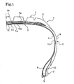
- Fig. 1 shows an example of a pneumatic tire manufactured by a pneumatic tire manufacturing method according to the present invention.
- Reference numeral T denotes the pneumatic tire; 1, a tread part; 2, a sidewall part; and 3, a bead part.
- a carcass layer 4 is extended between left and right bead parts 3.
- the carcass layer 4 is obtained by burying reinforcement cords in a rubber layer in a way that the reinforcement cords are arranged one after another in predetermined intervals in a tire circumferential direction.
- each reinforcement cord extends in a tire radial direction.
- Each of the two end portions of the carcass layer 4 is folded back around a bead core 5 buried in the bead part 3 from the tire inside to the tire outside in a tire axial direction in a way that the folded-back portions of each end portion of the carcass layer 4 interpose a bead filler 6.
- Multiple belt layers 7 and a belt reinforcement layer 7a are provided at the outer peripheral side of the carcass layer 4 in the tread part 1.
- a tread rubber layer 8 is provided at the outer peripheral side of the belt reinforcement layer 7a.
- a side rubber layer 9 is provided at the outer side of the carcass layer 4 in the sidewall part 2.
- a cushion rubber layer 10 is provided at the outer side of each folded-back portion of the carcass layer 4 in the bead part 3.
- An inner liner layer 11 is arranged in the inner side of the carcass layer 4.
- the inner liner layer 11 functions as an air-permeation preventing layer.
- multiple two-side fasteners 12 are intermittently attached to an inner surface 11a of the inner liner layer 11 at predetermined intervals in the tread part 1 in the tire circumferential direction.
- a belt-shaped protective rubber layer 13 is provided in an annular shape on the inner surface 11a in a way that all of the multiple two-side fasteners 12 are covered with the protective rubber layer 13.
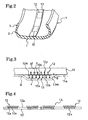
- Each two-side fastener 12 is made of a resin. As shown in Fig. 3 , each two-side fastener 12 has a structure in which engagement element groups 12x, 12y are provided in the two sides of a sheet-shaped base material (a base fabric) 12N, respectively. An attachment such as a noise absorbing material (not illustrated) is detachably engaged with the engagement element group 12x on a first side 12a of each two-side fastener 12 (a first side of the base material 12N). The engagement element group 12y on a second side 12b of the two-side fastener 12 (a second side of the base material 12N) is buried in the inner liner layer 11, and thus functions as anchor elements.
- multiple two-side fasteners 12 are intermittently attached to a first side 13'a of a belt-shaped protective rubber layer 13' made of an uncured rubber at predetermined intervals in the longitudinal direction of the protective rubber layer 13' in a way that the engagement element group 12x on the first side 12a of each two-side fastener 12 is buried in the first side 13'a of the protective rubber sheet 13'.
- a protective rubber layer 14 with the two-side fasteners is formed.
- each two-side fastener 12 should be as short as possible in the longitudinal direction of the protective rubber layer as long as the length of the two-side fastener is long enough for its corresponding attachment to be attached to the two-side fastener.
- a portion of the protective rubber layer 14 to which each two-side fastener 12 is attached is not stretched because the two-side fastener 12 restricts the portion of the protective rubber layer 14. Consequently, when a first formed body 22 is expanded as described later, the portion of the protective rubber layer 14 restricts the expansion of the carcass layer located inward of the protective rubber layer 14. For this reason, the intermittent arrangement of the multiple two-side fasteners 12 each formed shorter in length makes it possible to check the arrangement of the reinforcement cords in the carcass layer 4 from being put out of order.
- the protective rubber layer 14 with the two-side fasteners is entirely adhered onto (wound around) a making drum 21 into an annular shape with the multiple two-side fasteners 12 being located outward, and with the protective rubber layer 13' being located closer to the making drum 21.
- an uncured inner liner 11', an uncured carcass layer 4', a bead core 5 to which an uncured bead filler 6' is attached; an uncured cushion rubber layer 10' and an uncured side rubber layer 9' are sequentially adhered onto the protective rubber layer 14 with the two-side fasteners in the same manner as a conventional type of pneumatic tire.
- the first formed body 22 shaped like a cylinder is made, which has the left and right end portions being folded in the inner circumferential direction (see Fig. 6 ).
- the inner liner layer 11' is wound around the protective rubber layer 14 with the two-side fasteners in such a way as to be shaped like a cylinder with the engagement element groups 12y of the second sides 12b of the multiple two-side fasteners 12 being buried in the inner liner layer 11'. Subsequently, the other tire components constituting the first formed body 22 are adhered onto the inner liner layer 11' thus wounded. Thereby, the first formed body 22 is formed on the making drum 21.
- the first formed body 22 is removed from the making drum 21. As shown in Fig. 7 , the first formed body 22 thus removed is attached to a shaping drum 23. After that, an inflation pressure is applied to the first formed body 22 thus attached. Hence, the first formed body 22 is lifted. Thereby, the first formed body 22 is deformed into a toroidal shape by expansion. At this time, even if the inner circumferential length of the first formed body 22 is increased to a large extent, the two-side fasteners 12 do not fall off from the uncured inner liner layer 11'. That is because a rubber portion of the uncured inner liner layer 11' existing between each two neighboring two-side fasteners 12 stretches in response to the deformation of the first formed body 22 while not obstructed by the two-side fasteners 12.
- the first formed body 22 thus deformed into the toroidal shape by expansion is bonded to the inner circumference of a second formed body 24 arranged in the outer circumference of the first formed body 22 by compression.
- the second formed body 24 is obtained by adhering uncured belt layers 7', an uncured belt reinforcement layer 7a' and an uncured tread rubber layer 8' together, and is formed into an annular shape.
- the uncured tread rubber layer 8' is adhered to the outer circumference of the uncured belt reinforcement layer 7a'.
- the protective rubber layer 13' is cured by heating. Thereafter, the resultant green tire is set in a mold of a tire curing machine. After that, the green tire thus set is cured while being pressed from its inside to the mold by a bladder. At this time, the engagement element groups 12X provided to the first sides 12a of the two-side fasteners 12 for detachably attaching the attachment such as a noise absorbing material to the two-side fasteners 12 are protected by the protective rubber layer 13. For this reason, no engagement elements x of each engagement element group 12x are crushed by the pressing force of the bladder.
- the cured tire After its curing, the cured tire is removed from the tire curing machine. Thereby, the pneumatic tire T shown in Fig. 1 is obtained.
- the protective rubber layer 13 is attached to the pneumatic tire T shown in Fig. 1 , a pneumatic tire having no protective rubber layer 13 may be manufactured by removing the protective rubber layer 13 from the cured tire depending on the necessity.
- the first formed body 22 is made by adhering the protective rubber layer 14 with the two-side fasteners to the making drum 21 and then adhering the uncured inner liner layer 11' onto the protective rubber layer 14 with the two-side fasteners.
- the first formed body 22 may be made as follows.
- the protective rubber layer 14 with the two-side fasteners is beforehand laid on the inner liner layer 11' in a way that the engagement element groups 12y on the second sides 12b of the two-side fasteners 12 are buried in the inner liner layer 11' (see Fig. 8 ).
- a laminated body 15 obtained by laying the protective rubber layer 14 with the two-side fasteners on the inner liner layer 11' is wound around the making drum 21 into a cylindrical shape with the protective rubber layer 13' being located closer to the making drum 21.
- the other tire components constituting the first formed body 22 are adhered onto the laminated body 15. Thereby, the first formed body 22 is made.
- the present invention causes the first formed body 22 to be made by intermittently attaching the two-side fasteners 12 to the first formed body 22. For this reason, when the first formed body 22 is deformed into a toroidal shape by expansion, the rubber portion of the inner liner layer 11' between each two-side fasteners 12 attached to the inner line liner 11' is stretched by following the deformation of the first formed body 22 while not obstructed by the two-side fasteners 12. Accordingly, the present invention is capable of avoiding falling off of the two-side fasteners 12 from the inner liner layer 11'.
- the present invention makes it easy to attach the two-side fasteners to the first formed body 22, and is accordingly capable of enhancing the productivity.
- the present invention makes it possible to easily attach the two-side fasteners 12 to the respective predetermined locations on the making drum 21, and is accordingly capable of preventing the pneumatic tire from deteriorating its uniformity due to unbalanced attachments of the two-side fasteners 12.
- the present invention causes the protective rubber layer 13 to protect the engagement element groups 12x on the first sides 12a of the two-side fasters 12 to which the attachment such as a noise absorbing material is detachably attached, while the green tire is being cured, respectively. Accordingly, the present invention is capable of preventing the engagement element groups 12x from being crushed by the pressing force of the bladder.
- the present invention uses the two-side fasteners 12 instead of an adhesive or the like.
- the two-side fasteners 12 are attached to the inner liner layer 11' by use of the engagement element groups 12y on the second sides 12b of the two-side fasteners 12.
- no adhesive or the like needs to be applied to the fasteners 12 in this attachment. Accordingly, the present invention makes it easy to attach the fasteners 12 to the inner liner layer 11', and is thus capable of enhancing the productivity further.
- Figs. 9 to 11 show a second embodiment of the pneumatic tire manufacturing method according to the present invention.
- this manufacturing method causes a protective rubber layer 14 with a two-side fastener to be made by intermittently attaching a single belt-shaped two-side fastener 12 on a first side 13'a of a single belt-shaped protective rubber layer 13' made of an uncured rubber in a longitudinal direction of the protective rubber layer 13' in a way that engagement element groups 12x on a first side 12a of the two-side fastener 12 are buried in the first side 13'a of the protective rubber layer 13'.
- engagement element groups 12x are arranged on the first side 12a of the two-side fastener 12 at predetermined intervals in the longitudinal direction of the two-side fastener 12, whereas engagement element groups 12y are arranged on a second side 12b of the two-side fastener 12 at predetermined intervals in the longitudinal direction thereof.
- the belt-shaped two-side fastener 12 is cut between each two neighboring engagement element groups 12x or 12y.
- the two-side fastener 12 has a constitution in which multiple two-side fastener pieces 12A are arranged. From a viewpoint of a better balance, it is desirable that the belt-shaped two-side fastener 12 should be cut in the middle between each two neighboring engagement element groups 12x or 12y.
- the protective rubber layer 14 with the two-side fastener thus cut is wound entirely around a making drum 21 into an annular shape with the two-side fastener 12 being located outward, and with the protective rubber layer 13' being located closer to the making drum 21.
- the green tire is made.
- a rubber portion 11'r of an inner liner layer 11' between each two neighboring locations in which the two-side fastener pieces 12A are attached to the inner liner layer 11' is stretched by following the expanding deformation of the first formed body 22 (see Fig. 11 ).
- the two-side fastener 12 which is cut into the two-side fastener pieces 12A does not fall off from the inner liner layer 11'.
- the two-side fastener 12 is protected by the protective rubber layer 13 while the green tire is cured. Accordingly, the second embodiment is capable of offering the same effects as the first embodiment.
- the first formed body 22 may be similarly formed as follows.
- the protective rubber layer 14 with the two-side fastener thus cut is beforehand laid on the inner liner layer 11' in a way that the engagement element groups 12y on the second side 12b of the two-side fastener 12 are buried in the inner liner layer 11' (see Fig. 12 ).
- a laminated body 15 obtained by laying the protective rubber layer 14 with the two-side fastener on the inner liner layer 11' is wound around the making drum 21 into a cylindrical shape with the protective rubber layer 13' being located closer to the making drum 21.
- the other tire components constituting the first formed body 22 are adhered onto the laminated body 15. Thereby, the first formed body 22 is made.
- Figs. 13 to 16 show a third embodiment of the pneumatic tire manufacturing method according to the present invention.
- this manufacturing method causes a protective rubber layer 14 with a two-side fastener to be made by use of a single belt-shaped two-side fastener 12 as follows.
- Engagement element groups 12x are arranged on a first side 12a of the two-side fastener 12 at predetermined intervals in the longitudinal direction of the two-side fastener 12, whereas engagement element groups 12y are arranged on a second side 12b of the two-side fastener 12 at predetermined intervals in the longitudinal direction thereof.
- a cut line 16 is provided between each two neighboring engagement element groups 12x or 12y. As shown in Fig.
- this belt-shaped two-side fastener 12 is intermittently attached onto a first side 13'a of a single belt-shaped protective rubber layer 13' made of an uncured rubber in a longitudinal direction of the protective rubber layer 13' in a way that the engagement element groups 12x on the first side 12a are buried in the first side 13'a of the protective rubber layer 13'.
- the protective rubber layer 14 with the two-side fastener is made.
- the protective rubber layer 14 with the two-side fastener is wound entirely around a making drum 21 into an annular shape with the two-side fastener 12 being located outward, and with the protective rubber layer 13' being located closer to the making drum 21. Thereby, the green tire is made.
- a first formed body 22 is deformed into a toroidal shape by expansion, as shown in Fig.
- the belt-shaped two-side fastener 12 is cut into two-side fastener parts 12B along the cut lines 16, and a rubber portion 11'r of an inner liner layer 11' between each two neighboring locations in which the corresponding two-side fastener parts 12B are intermittently attached to the inner liner layer 11' is stretched by following the expanding deformation of the first formed body 22. For this reason, the two-side fastener 12 does not fall off from the inner liner layer 11'.
- the two-side fastener 12 is protected by the protective rubber layer 13 while the green tire is cured. Accordingly, the third embodiment is capable of offering the same effects as the foregoing embodiments.
- the first formed body 22 may be similarly formed as follows.
- the protective rubber layer 14 with the two-side fastener is beforehand laid on the inner liner layer 11' in a way that the engagement element groups 12y on the second side 12b of the two-side fastener 12 are buried in the inner liner layer 11' (see Fig. 16 ).
- a laminated body 15 obtained by laying the protective rubber layer 14 with the two-side fastener on the inner liner layer 11' is wound around the making drum 21 into a cylindrical shape with the protective rubber layer 13' being located closer to the making drum 21.
- the other tire components constituting the first formed body 22 are adhered onto the laminated body 15. Thereby, the first formed body 22 is made.
- Figs. 17 to 19 show a fourth embodiment of the pneumatic tire manufacturing method according to the present invention.
- a belt-shaped two-side fastener 12 is constituted as shown in Figs. 17 and 19 .
- engagement element groups 12x are arranged on a first side of a base material 12N at predetermined intervals
- engagement element groups 12y are arranged on a second side of the base material 12N at predetermined intervals.
- a folding line 17 crossing the two-side fastener 12 in a width direction thereof is formed in the middle of a base material portion 12Na between each two neighboring engagement element groups 12x or 12y. Thereby, each base material portion 12Na can be folded.
- This belt-shaped two-side fastener 12 is longer than the inner circumferential length of a first formed body 22 which is made on a making drum 21, and is almost as long as the inner circumferential length of the first formed body 22 which is deformed by expansion.
- the engagement element groups 12x on the first side 12a of the belt-shaped two-side fastener 12 are respectively covered with protective rubber layers 13' made of an uncured rubber.
- the two-side fastener 12 thus covered is laid on an inner liner layer 11' with the base material portion 12Na, located between each two neighboring engagement element groups 12x or 12y, being folded in a way that the engagement element groups 12y on the second side 12b of the two-side fastener 12 are buried in the inner liner layer 11'.
- the two-side fastener 12 is intermittently attached to the inner liner layer 11' in a longitudinal direction thereof with the engagement element groups 12y being in between in a way that each base material portion 12Na can be stretched in response.
- a laminated body 15 obtained by laying the two-side fastener 12 covered with the protective rubber layer 13' on the inner liner layer 11' is wound around the making drum 21 into a cylindrical shape with the protective rubber layer 13' being located closer to the making drum 21.
- the other tire components constituting the first formed body 22 are adhered onto the laminated body 15 thus wound.
- the first formed body 22 is made.
- a green tire is made.
- the fourth embodiment is capable of offering the same effects as the foregoing embodiments.
- Figs. 20 to 22 show a fifth embodiment of the pneumatic tire manufacturing method according to the present invention.
- this manufacturing method causes a single belt-shaped two-side fastener 12 to be attached to a belt-shaped protective rubber layer 13' made of an uncured rubber in a longitudinal direction of the protective rubber layer 13' in a way that a continuous engagement element group 12x on a first side of the two-side fastener 12 are buried in a first side 13'a of the protective rubber layer 13'.
- the continuous engagement element group 12x is provided on the first side of the two-side fastener 12
- a continuous engagement element group 12y is provided on a second side of the two-side fastener 12.
- a protective rubber layer 14 with the two-side fastener which is obtained by attaching the two-side fastener 12 to the protective rubber layer 13' is longer than the inner circumferential length of a first formed body 22 which is made on a making drum 21, and is almost as long as the inner circumferential length of the first formed body which is deformed by expansion.
- the protective rubber layer 13' is cured while the protective rubber layer 14 with the two-side fastener is formed into a meandering shape in its thickness direction.
- a protective rubber layer 14X with the two-side fastener formed into the meandering shape in its thickness direction is obtained.
- the protective rubber layer 14X with the two-side fastener thus formed is attached to an inner liner layer 11' in a way that the engagement element group 12y on the second side of the two-side fastener 12 is intermittently buried in the inner liner layer 11' at predetermined intervals.
- a complex 18 obtained by attaching the protective rubber layer 14X with the two-side fastener thus formed to the inner liner layer 11' is wound around the making drum 21 into a cylindrical shape with the protective rubber layer 13 being located closer to the making drum 21. Subsequently, in the same manner as is described above, the other tire components constituting the first formed body 22 are adhered onto the complex 18. Thereby, the first formed body 22 is made. Then, a green tire is made.
- the fifth embodiment is capable of offering the same effects as the foregoing embodiments.
- the first formed body 22 may be made as follows. After cured, the protective rubber layer 14X with the two-side fastener thus formed is wound around the making drum 21 into a cylindrical shape while kept formed with the two-side fastener 12 being located outward. Subsequently, the inner liner layer 11' is wound around this cylindrical protective rubber layer 14X with the two-side fastener thus formed into a cylindrical shape in a way that the engagement element group 12y on a second side 12b of the two-side fastener 12 is intermittently buried in the inner liner layer 11'. After that, the other tire components constituting the first formed body 22 are adhered onto the inner liner layer 11'. Thereby, the first formed body 22 is made.
- the embodiment shown in Figs. 20 to 22 uses the single belt-shaped two-side fastener 12. Nevertheless, as shown in Fig. 23 , multiple two-side fasteners 12 each shorter in length may be used for the embodiment.
- the two-side fasteners 12 are attached to first sides 13'a of protective rubber layers 13' in a way that the engagement element groups 12x on first sides 12a thereof are buried in the first sides 13'a, respectively.
- the protective rubber layers 13' are cured while protective rubber layers 14 with the two-side fasteners which are obtained by attaching the two-side fasteners 12 to the first sides 13'a is kept formed into the meandering shape in its thickness direction.
- protective rubber layers 14X with the two-side fasteners formed into the meandering shape in the thickness direction is obtained.
- the cured protective rubber layers 14X with the two-side fasteners thus formed are attached to the inner liner layer 11' at predetermined intervals in a longitudinal direction of the inner liner layer 11' in a way that the engagement element groups 12y on the second sides of the two-side fasteners 12 in the protective rubber layers 14X with the two-side fasteners thus formed are intermittently buried in the inner liner layer 11'.
- a complex 18 obtained by attaching the protective rubber layers 14X with two-side fasteners thus formed to the inner liner layer 11' is made.
- This complex 18 is wound around the making drum 21 into a cylindrical shape with the protective rubber layers 13 being closer to the making drum 21 as described above.
- the other tire components constituting the first formed body 22 are adhered onto the complex 18 thus wound. Thereby, the first formed body 22 is made. Then, a green tire is made.
- This manufacturing scheme is capable of offering the same effects as the foregoing embodiments.
- nylon or polyester may be cited as the resin used for the two-side fastener(s) 12. From a viewpoint of the heat resistance, it is desirable that nylon should be used. Nylon 6, nylon 66 and their co-polymer nylon can be included in examples of such nylon.
- the engagement elements x and y may be shaped into any form like a hook, a loop, a wedge or the like as long as the engagement elements x and y are capable of engaging with the attachment and the inner liner layer 11', respectively.
- each of the engagement elements x and y should be not less than 0.5 mm but not more than 2 mm in height. The heights of the engagement elements x and y in this range enhance the engagement effects.
- a surface treatment using a rubber releasing agent may be applied to the engagement elements x and y in the engagement element groups 12x and 12y of the two-side fastener 12.
- a rubber material used for the protective rubber layer(s) 13 should be selected from a viewpoint that the adhesiveness of the protective rubber layer (s) 13 with the engagement elements x and y in the engagement element groups 12x and 12y of the two-side fastener 12 needs to be lower.
- Nitrile-butadiene rubber (NBR) can be cited as a desirable example of the rubber material.
- the modulus of the protective rubber layer(s) 13 measured when the rubber is stretched by 100% should be set in a range of 0.2 MPa to 3 MPa. If the modulus thereof measured when the rubber is stretched by 100% is less than 0.2 MPa, the protective rubber layer (s) 13 is apt to tear while the pneumatic tire is under production.
- the protective rubber layer (s) 13 is hard to be stretched in the stretch of the pneumatic tire (apt to fall off from the tire).
- the modulus of the protective rubber layer (s) 13 should be measured by use of a No. 3 dumbbell specimen in accordance with JIS (Japanese Industrial Standards) K6251 when the rubber is stretched by 100%.
- each engagement element y of the engagement element group (s) 12y should be formed as an enlarged portion y1 (see Fig. 3 ) which is not less than 0.3 mm but not more than 1 mm in width.
- the width of the enlarged portion y1 is set at 0.3 mm or more, the anchor effect of the engagement element group (s) 12y can be increased.
- the width thereof is set at 1 mm or more, the engagement element group (s) 12y is made difficult to anchor into the rubber.
- the protective rubber layer(s) 13 may be formed into any shape as long as the protective rubber layer (s) 13 is capable of protecting the engagement element group(s) 12x. It is desirable that, as shown in Fig. 3 , the tire meridional cross-section of the protective rubber layer(s) 13 should be shaped like a trapezoid in which a base closer to the two-side fastener 12 is longer than the other base. When the tire meridional cross-section of the protective rubber layer(s) 13 is shaped like such a trapezoid, a bladder B is likely to be brought into intimate contact with the protective rubber layer(s) 13 when the protective rubber layer(s) 13 is pressed with the bladder B.
- an angle ⁇ of an acute section 13m in the cross section of the trapezoid-shaped protective rubber layer (s) 13 should be set at 45° or less from a viewpoint of an effect of checking air holes. It is desirable that the lower limit of the angle ⁇ should be set at least 5° from a viewpoint of the manufacturing of the pneumatic tire.
- the tire in which the two-side fastener(s) 12 is provided with the protective rubber layer (s) 13 is manufactured, as shown in Fig. 24 , it is desirable to use the bladder B in which a thickness T1 of its portion corresponding to the protective rubber layer 13 is thinner than a thickness T2 of its surrounding portion.
- the protective rubber layer 13 is provided to the two-side fastener 12
- heat applied to the bladder B when the green tire is cured is hard to be conducted to the inner liner layer 11' in a part of the bladder B in which the protective rubber layer 13 exists.
- the thickness T1 of the portion of the bladder B corresponding to the protective rubber layer 13 is set thinner than the thickness T2 of the surrounding portion of the bladder B. This makes it better for the heat to be conducted to the inner liner layer 11' through the part of the bladder B in which the protective rubber layer (s) 13 exist. Accordingly, it is possible to make the curing condition even throughout the green tire.
- the two-side fastener(s) 12 should be directly attached to the inner liner layer 11' from viewpoint of the weight.
- a rear rubber layer 30 made of an uncured rubber which is the same as the uncured rubber constituting the inner liner layer 11' may be laid on each second side 12b of the two-side fastener (s) 12.
- the thickness of the inner liner layer 11' should be partially thin by a thickness corresponding to the thickness of the rear rubber layer 30 in a location in which the two-side fastener 12 is arranged on the inner liner layer 11'.
- the protective rubber layer(s) 13 is finally removed from the tire, because the attachment such as a noise absorbing material is attached to the engagement element group(s) 12x on the first side(s) 12a of the two-side fastener 12.
- the attachment such as a noise absorbing material
- the protective rubber layer (s) 13 should be cured before the green tire is cured from a viewpoint of enhancing the protecting effect which the protective rubber layer(s) 13 has on the engagement element group (s) 12x of the two-side fastener (s) 12.
- the protective rubber layer(s) 13 may be cured simultaneously when the green tire is cured.
- the case in which the pneumatic tire T with the two-side fastener(s) 12 being attached to its tire inner surface 1a in its center portion 1A on its tread part 1 is manufactured has been shown for each foregoing embodiment.
- the manufacturing method according to the present invention is not limited to this.
- the manufacturing method according to the present invention may be that by which a pneumatic tire with a two-side fastener(s) 12 being attached to its tire inner surface 1b in each of its two shoulder parts 1B on its tread part 1 (see Fig. 27 ).
Landscapes
- Engineering & Computer Science (AREA)
- Mechanical Engineering (AREA)
- Tyre Moulding (AREA)
- Tires In General (AREA)
Claims (15)
- Herstellungsverfahren für einen Luftreifen, durch Fertigen eines Reifenrohlings, der zweiseitige Befestigungsmittel (12) in dessen Reifeninnenoberfläche (1a) entlang dessen Reifenumfangsrichtung aufweist, wobei jedes zweiseitige Befestigungsmittel (12) eine Eingriffselementgruppe (12X, 12Y) auf beiden Seiten enthält, wobei das Verfahren die Schritte umfasst:Abdecken der Eingriffselementgruppen (12X) auf ersten Seiten der zweiseitigen Befestigungsmittel (12) mit einer Schutzgummischicht (13'), die aus einem ungehärteten Gummi gefertigt ist;Herstellen eines ersten zylindrisch ausgebildeten Körpers (23) auf einer Herstellungstrommel (21), wobei die zweiseitigen Befestigungsmittel (12) mit der Schutzgummischicht (13') abgedeckt werden, die an einer Innenumfangsoberfläche des ersten ausgebildeten Körpers (22) in einer Umfangsrichtung davon intermittierend aufgebracht sind, wobei die Eingriffselementgruppen (12Y) auf zweiten Seiten der zweiseitigen Befestigungsmittel (12) dazwischen vorgesehen sind;Verbinden des ersten ausgebildeten Körpers (22) mit einem Innenumfang eines ringförmigen zweiten ausgebildeten Körpers (24) mittels Kompression durch Erweitern des ersten ausgebildeten Körpers (22) in eine toroidförmige Gestalt, und dadurch Herstellen des Reifenrohlings; undAushärten des Reifenrohlings in einer Form einer Aushärtungsanlage, während der Reifenrohling von seiner Innenseite mittels einer Blase (B) gepresst wird.
- Herstellungsverfahren für einen Luftreifen nach Anspruch 1, bei dem der Herstellungsschritt des ersten ausgebildeten Körpers umfasst:Anbringen der zweiseitigen Befestigungsmittel (12) auf eine Seite der Schutzgummischicht (13'), die wie ein Gürtel ausgeformt ist, in bestimmten Abständen in einer Längsrichtung der Schutzgummischicht (13'), auf eine Weise, dass Eingriffselementgruppen (12X) auf den ersten Seiten der zweiseitigen Befestigungsmittel (12) in der Schutzgummischicht (13') verborgen sind;Wickeln der Schutzgummischicht (14), welche die zweiseitigen Befestigungsmittel aufweist, um die Herstellungstrommel (21) in eine zylindrische Form, wobei die zweiseitigen Befestigungsmittel (12) außen vorgesehen sind;Wickeln einer Innenmantelschicht (11') um die zylindrische Schutzgummischicht (14), welche die zweiseitigen Befestigungsmittel aufweist, in eine zylindrische Form, auf eine Weise, dass die Eingriffselementgruppen (12Y) auf den zweiten Seiten der zweiseitigen Befestigungsmittel (12) in der Innenmantelschicht (11') verborgen sind; undKleben der anderen Reifenkomponenten (4', 5', 6', 9', 10'), welche den ersten ausgebildeten Körper (22) bilden, auf die Innenmantelschicht (11').
- Herstellungsverfahren für einen Luftreifen nach Anspruch 1, bei dem die Herstellungsschritte des ersten ausgebildeten Körpers umfassen:Anbringen der zweiseitigen Befestigungsmittel (12) auf eine Seite der Schutzgummischicht (13'), die wie ein Gürtel geformt ist, in bestimmten Abständen in einer Längsrichtung der Schutzgummischicht (13'), auf eine Weise, dass die Eingriffselementgruppen (12X) auf den ersten Seiten der zweiseitigen Befestigungsmittel (12) in der Schutzgummischicht (13') verborgen sind;Ablegen der Schutzgummischicht (14), welche die zweiseitigen Befestigungsmittel aufweist, auf eine Innenmantelschicht (11'), auf eine Weise, dass die Eingriffselementgruppen (12Y) auf den zweiten Seiten der zweiseitigen Befestigungsmittel (12) in der Innenmantelschicht (11') verborgen sind;Wickeln eines Schichtkörpers (15), der durch Ablegen der Schutzgummischicht (14), welche die zweiseitigen Befestigungsmittel aufweist, auf die Innenmantelschicht (11') erhalten wird, um die Herstellungstrommel (21) in eine zylindrische Form, wobei die Schutzgummischicht (13') näher an die Herstellungstrommel (21) positioniert wird; undKleben der anderen Reifenkomponenten (4', 5', 6', 9', 10'), welche den ersten ausgebildeten Körper (22) bilden, auf den Schichtkörper (15).
- Herstellungsverfahren für einen Luftreifen nach Anspruch 1, bei dem der Herstellungsschritt des ersten ausgebildeten Körpers umfasst:Anbringen eines gürtelförmigen zweiseitigen Befestigungsmittels (12) auf eine Seite einer gürtelförmigen Schutzgummischicht (13') in einer Längsrichtung der Schutzgummischicht (13'), auf eine Weise, dass die Eingriffselementgruppen (12X) auf einer ersten Seite des zweiseitigen Befestigungsmittels (12) in der Schutzgummischicht (13') verborgen sind, wobei die Eingriffselementgruppen (12X, 12Y) auf beiden Seiten des zweiseitigen Befestigungsmittels (12) in bestimmten Abständen in einer Längsrichtung davon angeordnet sind;Schneiden des zweiseitigen Befestigungsmittels (12) der Schutzgummischicht (14), welche das zweiseitige Befestigungsmittel aufweist, an einem Ort zwischen jeweils zwei benachbarten Eingriffselementgruppen (12X, 12Y);Wickeln der Schutzgummischicht (14), welche das somit geschnittene zweiseitige Befestigungsmittel aufweist, um die Herstellungstrommel (21) in eine zylindrische Form, wobei das zweiseitige Befestigungsmittel (12) außen vorgesehen ist;Wickeln einer Innenmantelschicht (11') um die zylindrische Schutzgummischicht (14), welche das zweiseitige Befestigungsmittel aufweist, in eine zylindrische Form, auf eine Weise, dass die Eingriffselementgruppen (12Y) auf der zweiten Seite des zweiseitigen Befestigungsmittels (12) in der Innenmantelschicht (11') verborgen sind; undKleben der anderen Reifenkomponenten (4', 5', 6', 9', 10'), welche den ersten ausgebildeten Körper (22) bilden, auf die Innenmantelschicht (11').
- Herstellungsverfahren für einen Luftreifen nach Anspruch 1, bei dem der Herstellungsschritt des ersten ausgebildeten Körpers umfasst:Anbringen eines gürtelförmigen zweiseitigen Befestigungsmittels (12) auf eine Seite einer gürtelförmigen Schutzgummischicht (13') in einer Längsrichtung der Schutzgummischicht (13'), auf eine Weise, dass die Eingriffselementgruppen (12X) auf der ersten Seite des zweiseitigen Befestigungsmittels (12) in der Schutzgummischicht (13') verborgen sind, wobei die Eingriffselementgruppen (12X, 12Y) auf beiden Seiten des zweiseitigen Befestigungsmittels (12) in bestimmten Abständen in einer Längsrichtung davon angeordnet sind;Schneiden des zweiseitigen Befestigungsmittels (12) der Schutzgummischicht (14), welche das zweiseitige Befestigungsmittel aufweist, an einem Ort zwischen jeweils zwei benachbarten Eingriffselementgruppen (12X, 12Y);Ablegen der Schutzgummischicht (14), welche das somit geschnittene zweiseitige Befestigungsmittel aufweist, auf eine Innenmantelschicht (11'), auf eine Weise, dass die Eingriffselementgruppen (12Y) auf einer zweiten Seite des zweiseitigen Befestigungsmittels (12) in der Innenmantelschicht (11') verborgen sind;Wickeln eines Schichtkörpers (15), der durch Ablegen der Schutzgummischicht (14), welche das somit geschnittene zweiseitige Befestigungsmittel aufweist, auf die Innenmantelschicht (11') erhalten wird, um die Herstellungstrommel (21) in eine zylindrische Form, wobei die Schutzgummischicht (13') näher an der Herstellungstrommel (21) positioniert ist; undKleben der anderen Reifenkomponenten (4', 5', 6', 9', 10'), welche den ersten ausgebildeten Körper (22) bilden, auf den Schichtkörper (15).
- Herstellungsverfahren für einen Luftreifen nach Anspruch 1, bei dem der Herstellungsschritt des ersten ausgebildeten Körpers umfasst:Anbringen eines gürtelförmigen zweiseitigen Befestigungsmittels (12) auf eine Seite einer gürtelförmigen Schutzgummischicht (13') in einer Längsrichtung der Schutzgummischicht (13'), auf eine Weise, dass die Eingriffselementgruppen (12X) auf einer ersten Seite des zweiseitigen Befestigungsmittels (12) in der Schutzgummischicht (13') verborgen sind, wobei die Eingriffselementgruppen (12X, 12Y) auf beiden Seiten des zweiseitigen Befestigungsmittels (12) in bestimmten Abständen in einer Längsrichtung des zweiseitigen Befestigungsmittels (12) angeordnet sind und das zweiseitige Befestigungsmittel (12) mit einer Schnittlinie (16) zwischen jeweils zwei benachbarten Gruppen des Eingriffselements (12X, 12Y) vorgesehen ist;Wickeln der Schutzgummischicht (14), welche das zweiseitige Befestigungsmittel aufweist, um die Herstellungstrommel (21) in einer zylindrischen Form, wobei das zweiseitige Befestigungsmittel (12) außen positioniert ist;Wickeln einer Innenmantelschicht (11') um die zylindrische Schutzgummischicht (14), welche das zweiseitige Befestigungsmittel aufweist, in eine zylindrische Form, auf eine Weise, dass die Eingriffselementgruppen (12Y) auf einer zweiten Seite des zweiseitigen Befestigungsmittel (12) in der Innenmantelschicht (11') verborgen sind; undKleben der anderen Reifenkomponenten (4', 5', 6', 9', 10'), welche den ersten ausgebildeten Körper (22) bilden, auf die Innenmantelschicht (11').
- Herstellungsverfahren für einen Luftreifen nach Anspruch 1, bei dem der Herstellungsschritt des ersten ausgebildeten Körpers umfasst:Anbringen eines gürtelförmigen zweiseitigen Befestigungsmittels (12) auf eine Seite einer gürtelförmigen Schutzgummischicht (13') in einer Längsrichtung der Schutzgummischicht (13'), auf eine Weise, dass die Eingriffselementgruppen (12X) auf einer ersten Seite des zweiseitigen Befestigungsmittels (12) in der Schutzgummischicht (13') verborgen sind, wobei die Eingriffselementgruppen (12X, 12Y) auf beiden Seiten des zweiseitigen Befestigungsmittels (12) in bestimmten Abständen in einer Längsrichtung des zweiseitigen Befestigungsmittels (12) angeordnet sind und das zweiseitige Befestigungsmittel (12) mit einer Schnittlinie (16) zwischen jeweils zwei benachbarten Eingriffselementgruppen (12X, 12Y) vorgesehen ist;Ablegen der Schutzgummischicht (14), welche das zweiseitige Befestigungsmittel aufweist, auf eine Innenmantelschicht (12'), auf eine Weise, dass die Eingriffselementgruppen (12Y) auf einer zweiten Seite des zweiseitigen Befestigungsmittels (12) in der Innenmantelschicht (11') verborgen sind;Wickeln eines Schichtkörpers (15), der durch Ablegen der Schutzgummischicht (14), welche das zweiseitige Befestigungsmittel aufweist, auf Innenmantelschicht (11') erhalten wird, um die Herstellungstrommel (21) in eine zylindrische Form, wobei die Schutzgummischicht (13') näher an der Herstellungstrommel (21) positioniert ist; undKleben der anderen Reifenkomponenten (4', 5', 6', 9', 10'), welche den ersten ausgebildeten Körper (22) bilden, auf den Schichtkörper (15).
- Herstellungsverfahren für einen Luftreifen nach Anspruch 1, bei dem der Herstellungsschritt des ersten ausgebildeten Körpers umfasst:Abdecken der Eingriffselementgruppen (12X) auf einer ersten Seite eines gürtelförmigen zweiseitigen Befestigungsmittels (12) mit der Schutzgummischicht (13'), die aus dem ungehärteten Gummi gefertigt ist, wobei die Eingriffselementgruppen (12X, 12Y) auf beiden Seiten des zweiseitigen Befestigungsmittels (12) in bestimmten Abständen in einer Längsrichtung des zweiseitigen Befestigungsmittels (12) angeordnet sind;Ablegen des gürtelförmigen zweiseitigen Befestigungsmittels (12), das mit der Schutzgummischicht (13') abgedeckt ist, auf eine Innenmantelschicht (11'), auf eine Weise, dass die Eingriffselementgruppen (12Y) auf einer zweiten Seite des zweiseitigen Befestigungsmittels (12) in der Innenmantelschicht (11') verborgen sind, wobei ein Teil des zweiseitigen Befestigungsmittels (12) zwischen jeweils zwei benachbarten Eingriffselementgruppen (12X, 12Y) gefaltet wird;Wickeln eines Schichtkörpers (15) der durch Ablegen des zweiseitigen Befestigungsmittels (11), das mit der Schutzgummischicht (13') abgedeckt ist, auf die Innenmantelschicht (11') erhalten wird, um die Herstellungstrommel (21) in eine zylindrische Form, wobei das zweiseitige Befestigungsmittel (12) näher an der Herstellungstrommel (21) positioniert ist; undKleben der anderen Reifenkomponenten (4', 5', 6', 9', 10'), welche den ersten ausgebildeten Körper (22) bilden, auf den Schichtkörper (15).
- Herstellungsverfahren für einen Luftreifen nach einem der Ansprüche 1 bis 8, bei dem die Schutzgummischicht (13'), die aus dem ungehärteten Gummi gefertigt ist, vor dem Härten des Reifenrohlings gehärtet wird.
- Herstellungsverfahren für einen Luftreifen nach Anspruch 1, bei dem der Herstellungsschritt des ersten ausgebildeten Körpers umfasst:Anbringen eines gürtelförmigen zweiseitigen Befestigungsmittels (12) auf eine Seite einer gürtelförmigen Schutzgummischicht (13') in einer Längsrichtung der Schutzgummischicht (13'), auf eine Weise, dass die Eingriffselementgruppen (12X) auf einer ersten Seite des zweiseitigen Befestigungsmittels (12) in der Schutzgummischicht (13') verborgen sind, wobei die Eingriffselementgruppen (12X, 12Y) auf beiden Seiten des zweiseitigen Befestigungsmittels (12) vorgesehen sind;Aushärten der Schutzgummischicht (14), welche das zweiseitige Befestigungsmittel aufweist, während die Schutzgummischicht (13') in eine Meanderform in einer Dickenrichtung davon ausgebildet wird;Anbringen der somit gehärteten und ausgebildeten Schutzgummischicht (14X), welche das zweiseitige Befestigungsmittel aufweist, auf eine Innenmantelschicht (11'), auf eine Weise, dass die Eingriffselementgruppen (12Y) auf einer zweiten Seite des zweiseitigen Befestigungsmittels (12) intermittierend in der Innenmantelschicht (11') verborgen sind;Wickeln eines Komplexes (18) um die Herstellungstrommel (21) in eine zylindrische Form, wobei die Schutzgummischicht (13') näher an der Herstellungstrommel (21) positioniert ist, wobei der Komplex (18) durch Anbringen der Schutzgummischicht (14X), welche das somit ausgebildete zweiseitige Befestigungsmittel aufweist, an die Innenmantelschicht (11') erhalten wird; undKleben der anderen Reifenkomponenten (4', 5', 6', 9', 10'), die den ersten ausgebildeten Körper (22) bilden, auf dem Komplex (18).
- Herstellungsverfahren für einen Luftreifen nach Anspruch 1, bei dem der Herstellungsschritt des ersten ausgebildeten Körpers umfasst:Anbringen eines gürtelförmigen zweiseitigen Befestigungsmittels (12) auf eine Seite der gürtelförmigen Schutzgummischicht (13') in einer Längsrichtung der Schutzgummischicht (13'), auf eine Weise, dass die Eingriffselementgruppen (12X) auf der ersten Seite des zweiseitigen Befestigungsmittels (12) in der Schutzgummischicht (13') verborgen sind, wobei die Eingriffselementgruppen (12X, 12Y) auf beiden Seiten des zweiseitigen Befestigungsmittels (12) vorgesehen sind;Aushärten der Schutzgummischicht (14), welche das zweiseitige Befestigungsmittel aufweist, während die Schutzgummischicht (13') in eine Meanderform in einer Dickenrichtung davon ausgebildet wird;Wickeln der somit gehärteten und ausgebildeten Schutzgummischicht (14X), welche das zweiseitige Befestigungsmittel aufweist, um die Herstellungstrommel (21) in eine zylindrischen Form, wobei die Schutzgummischicht (13') näher an der Herstellungstrommel (21) positioniert ist, während die Schutzgummischicht (14X), welche das zweiseitige Befestigungsmittel aufweist, in der Meanderform ausgebildet beibehalten wird;Wickeln der Innenmantelschicht (11') um die somit ausgebildete zylindrische Schutzgummischicht (14X), welche das zweiseitige Befestigungsmittel aufweist, in eine zylindrische Gestalt, auf eine Weise, dass die Eingriffselementgruppen (12Y) auf einer zweiten Seite des zweiseitigen Befestigungsmittels (22) in der Innenmantelschicht (11') intermittierend verborgen sind; undKleben der anderen Reifenkomponenten (4', 5', 6', 9', 10'), die den ersten ausgebildeten Körper (22) bilden, auf die Innenmantelschicht (11').
- Herstellungsverfahren für einen Luftreifen nach Anspruch 1, bei dem der Herstellungsschritt des ersten ausgebildeten Körpers umfasst:Anbringen der zweiseitigen Befestigungsmittel (22) entsprechend auf erste Seiten einer Mehrzahl von Schutzgummischichten (13'), auf eine Weise, dass die Eingriffselementgruppen (12Y) auf der ersten Seite von jedem zweiseitigen Befestigungsmittel (12) in einer entsprechenden der Schutzgummischichten (13') verborgen sind, wobei die Eingriffselementgruppen (12X, 12Y) auf beiden Seiten von jedem zweiseitigen Befestigungsmittel (12) vorgesehen sind;Aushärten der Schutzgummischichten (13'), welche die zweiseitigen Befestigungsmittel aufweisen, während die Schutzgummischichten (13') meanderförmig in einer Dickenrichtung davon ausgebildet werden;Anbringen der somit ausgehärteten und ausgebildeten Schutzgummischichten (14X), welche die zweiseitigen Befestigungsmittel aufweisen, an eine Innenmantelschicht (11') in bestimmten Abständen in einer Längsrichtung der Innenmantelschicht (11'), auf eine Weise, dass die Eingriffselementgruppen (12Y) auf einer zweiten Seite von jedem zweiseitigen Befestigungsmittel (12) in der Innenmantelschicht (11') intermittierend verborgen sind;Wickeln eines Komplexes (18) um die Herstellungstrommel (21) in eine zylindrische Form, wobei die Schutzgummischichten (13') näher an der Herstellungstrommel (21) positioniert sind, wobei der Komplex (18) durch Anbringen der somit ausgebildeten Schutzgummischichten (14X), welche die zweiseitigen Befestigungsmittel aufweisen, an der Innenmantelschicht (11') erhalten wird; undKleben der anderen Reifenkomponenten (4', 5', 6', 9', 10'), welche den ersten ausgebildeten Körper (22) bilden, auf den Komplex (18).
- Herstellungsverfahren für einen Luftreifen nach einem der Ansprüche 1 bis 8 und 10 bis 12, bei dem ein Modul, das gemessen wird, wenn der Gummi der Schutzgummischicht oder der Schutzgummischichten (13) um 100% gedehnt wird, 0,2 MPa bis 3 MPa beträgt.
- Herstellungsverfahren für einen Luftreifen nach einem der Ansprüche 1 bis 8 und 10 bis 12, bei dem die Schutzgummischicht oder die Schutzgummischichten (13) entfernt werden, nachdem der Reifenrohling ausgehärtet ist.
- Luftreifen, der zweiseitige Befestigungsmittel (12) in seiner Reifeninnenoberfläche in seiner Reifenumfangsrichtung aufweist, wobei jedes zweiseitige Befestigungsmittel (12) eine Eingriffselementgruppe (12X, 12Y) auf beiden Seiten enthält, wobei die Eingriffselementgruppen auf ersten Seiten der zweiseitigen Befestigungsmittel (12) mit einer Schutzgummischicht (13') abgedeckt sind, wobei der Luftreifen gemäß dem Herstellungsverfahren für einen Luftreifens nach einem der Ansprüche 1 bis 13 hergestellt ist.
Applications Claiming Priority (1)
| Application Number | Priority Date | Filing Date | Title |
|---|---|---|---|
| JP2007332393A JP4989449B2 (ja) | 2007-12-25 | 2007-12-25 | 空気入りタイヤの製造方法及び空気入りタイヤ |
Publications (2)
| Publication Number | Publication Date |
|---|---|
| EP2075112A1 EP2075112A1 (de) | 2009-07-01 |
| EP2075112B1 true EP2075112B1 (de) | 2011-05-18 |
Family
ID=40491122
Family Applications (1)
| Application Number | Title | Priority Date | Filing Date |
|---|---|---|---|
| EP08021067A Ceased EP2075112B1 (de) | 2007-12-25 | 2008-12-04 | Luftreifenherstellungsverfahren und Luftreifen |
Country Status (4)
| Country | Link |
|---|---|
| US (2) | US8444795B2 (de) |
| EP (1) | EP2075112B1 (de) |
| JP (1) | JP4989449B2 (de) |
| CN (1) | CN101468522B (de) |
Families Citing this family (26)
| Publication number | Priority date | Publication date | Assignee | Title |
|---|---|---|---|---|
| JP4760760B2 (ja) * | 2007-04-06 | 2011-08-31 | 横浜ゴム株式会社 | 空気入りタイヤ |
| AU2010286588B2 (en) * | 2009-08-28 | 2016-02-04 | Nanlin Han | 3-Dimension fiber structures for composites and interfaces |
| US20110308704A1 (en) * | 2010-06-21 | 2011-12-22 | Paul Harry Sandstrom | Method for making pneumatic tire with foam noise damper |
| US20110308706A1 (en) * | 2010-06-21 | 2011-12-22 | The Goodyear Tire & Rubber Company | Method for making pneumatic tire with foam noise damper |
| JP5496797B2 (ja) * | 2010-07-05 | 2014-05-21 | 横浜ゴム株式会社 | 空気入りタイヤ |
| JP5819047B2 (ja) * | 2010-07-27 | 2015-11-18 | 横浜ゴム株式会社 | 空気入りタイヤ |
| JP5862072B2 (ja) * | 2011-06-30 | 2016-02-16 | 横浜ゴム株式会社 | 空気入りタイヤの製造方法 |
| WO2013191692A1 (en) * | 2012-06-21 | 2013-12-27 | Compagnie Generale Des Etablissements Michelin | Method for adhering an innerliner to a carcass ply of a tire |
| US10052834B2 (en) * | 2012-10-16 | 2018-08-21 | The Goodyear Tire & Rubber Company | Protective structure for a retreaded air maintenance tire |
| JP6002562B2 (ja) * | 2012-12-05 | 2016-10-05 | 横浜ゴム株式会社 | 面ファスナー付き空気入りタイヤ及びその製造方法 |
| JP6318515B2 (ja) | 2013-09-24 | 2018-05-09 | 横浜ゴム株式会社 | 空気入りタイヤおよびその製造方法 |
| WO2015190410A1 (ja) * | 2014-06-09 | 2015-12-17 | 横浜ゴム株式会社 | 空気入りタイヤとその製造方法 |
| JP6413368B2 (ja) * | 2014-06-10 | 2018-10-31 | 横浜ゴム株式会社 | タイヤ内腔に面ファスナーを有する空気入りタイヤの製造方法 |
| EP3212390B1 (de) * | 2014-10-29 | 2021-06-30 | Pirelli Tyre S.p.A. | Verfahren und vorrichtung zum automatischen aufbringen eines geräuschdämpfenden elements auf einen reifen für fahrzeugräder |
| JP6516456B2 (ja) | 2014-12-02 | 2019-05-22 | 横浜ゴム株式会社 | 空気入りタイヤ及びその製造方法 |
| JP5994874B2 (ja) * | 2015-01-30 | 2016-09-21 | 横浜ゴム株式会社 | 空気入りタイヤ及びその製造方法 |
| KR101775797B1 (ko) * | 2015-11-30 | 2017-09-06 | 한국타이어 주식회사 | 흡음재 고정밴드를 구비하는 타이어 흡음재고정구조 및 이의 포함하여 제조되는 타이어 |
| DE112017002135B4 (de) * | 2016-04-22 | 2024-08-14 | The Yokohama Rubber Co., Ltd. | Luftreifen |
| US11433717B2 (en) | 2016-11-22 | 2022-09-06 | Pirelli Tyre S.P.A. | Process for applying noise-reducing elements to a tyre for vehicle wheels |
| DE112016007492B4 (de) * | 2016-11-30 | 2024-01-04 | The Yokohama Rubber Co., Ltd. | Luftreifen |
| WO2018147347A1 (ja) * | 2017-02-10 | 2018-08-16 | クラレファスニング株式会社 | 固定用ベルト、固定方法及び固定用ベルト用部材 |
| BR112020000734B1 (pt) * | 2017-07-27 | 2023-03-21 | Pirelli Tyre S.P.A | Processo para produzir pneus, e, conjunto de pneus para rodas de veículos |
| JP2019089410A (ja) * | 2017-11-13 | 2019-06-13 | 株式会社ブリヂストン | タイヤ |
| JP2019089409A (ja) * | 2017-11-13 | 2019-06-13 | 株式会社ブリヂストン | タイヤ |
| EP3793846B1 (de) | 2018-05-15 | 2025-05-28 | Bridgestone Americas Tire Operations, LLC | Reifen mit mehrschichtigem einsatz |
| JP7238562B2 (ja) | 2019-04-11 | 2023-03-14 | 横浜ゴム株式会社 | 空気入りタイヤ |
Family Cites Families (24)
| Publication number | Priority date | Publication date | Assignee | Title |
|---|---|---|---|---|
| US3712362A (en) | 1970-10-01 | 1973-01-23 | S Alderfer | A pneumatic tire without bead reinforcement rings |
| US4105487A (en) | 1975-12-27 | 1978-08-08 | Bridgestone Tire Company Limited | Process of and an apparatus for producing green tires |
| US5085942A (en) | 1985-01-22 | 1992-02-04 | The Uniroyal Goodrich Tire Company | Sealant product, laminate thereof, and pneumatic tire constructed therewith |
| US5540970A (en) * | 1991-05-03 | 1996-07-30 | Velcro Industries B.V. | Die cut mold-in |
| DE4120878C2 (de) | 1991-06-21 | 1996-04-18 | Bayerische Motoren Werke Ag | Fahrzeugreifen mit geräuschmindernder Konstruktion |
| EP0613767B1 (de) * | 1993-03-04 | 1998-06-10 | Bridgestone Corporation | Verfahren zum Aufbauen von Rohreifen |
| GB9916914D0 (en) * | 1999-07-20 | 1999-09-22 | Sumitomo Rubber Ind | Method of attaching an article to the inside of a tyre cavity |
| JP2001187502A (ja) | 1999-12-28 | 2001-07-10 | Sumitomo Rubber Ind Ltd | リム及びそれを用いたタイヤとリムの組立体 |
| CN1229216C (zh) * | 2000-03-14 | 2005-11-30 | 维尔克鲁工业公司 | 形成连接物制品的方法 |
| JP4932127B2 (ja) * | 2000-12-29 | 2012-05-16 | ピレリ・タイヤ・ソチエタ・ペル・アツィオーニ | 空気タイヤを製造するための方法および装置 |
| JP2005507677A (ja) * | 2001-05-29 | 2005-03-24 | ベルクロ インダストリーズ ビー ヴィッ | 個別締結部材領域の形成 |
| CA2828019C (en) * | 2002-02-18 | 2015-05-19 | Bridgestone Firestone North American Tire, Llc | Attachment method for tire tag |
| JP3659956B2 (ja) | 2002-11-11 | 2005-06-15 | 松下電器産業株式会社 | 圧力測定装置および圧力測定システム |
| US7332047B2 (en) * | 2002-12-03 | 2008-02-19 | The Goodyear Tire & Rubber Company | Adherent, removable barrier film for tire carcass |
| JP4274312B2 (ja) * | 2003-03-25 | 2009-06-03 | 横浜ゴム株式会社 | 空気入りタイヤの製造方法 |
| US7556075B2 (en) * | 2003-08-04 | 2009-07-07 | The Yokohama Rubber Co., Ltd. | Low noise pneumatic tire |
| JP4052290B2 (ja) * | 2003-08-29 | 2008-02-27 | オムロン株式会社 | 無線icタグ接合方法、無線icタグ付き物品、及び車両 |
| EP1574360B1 (de) * | 2004-03-10 | 2012-05-09 | Sumitomo Rubber Industries, Ltd. | Schalldämpfer |
| US7353720B2 (en) * | 2004-07-09 | 2008-04-08 | Michelin Recherche Et Technique, S.A. | Bridge patch for electromechanical transducer elements in tire assemblies |
| JP3916625B2 (ja) * | 2004-08-05 | 2007-05-16 | 横浜ゴム株式会社 | 空気入りタイヤ |
| ATE521486T1 (de) * | 2004-10-27 | 2011-09-15 | Pirelli | Luftreifen für fahrzeug, verfahren und vorrichtung zu seiner herstellung |
| JP2007022043A (ja) * | 2005-07-21 | 2007-02-01 | Bridgestone Corp | 台座付タイヤの製造方法 |
| JP4532520B2 (ja) * | 2007-04-25 | 2010-08-25 | 横浜ゴム株式会社 | 面ファスナー付き空気入りタイヤ及びその製造方法 |
| US20090000718A1 (en) * | 2007-06-28 | 2009-01-01 | Dirk Frans Rouckhout | Air barrier composition |
-
2007
- 2007-12-25 JP JP2007332393A patent/JP4989449B2/ja not_active Expired - Fee Related
-
2008
- 2008-12-04 EP EP08021067A patent/EP2075112B1/de not_active Ceased
- 2008-12-12 US US12/334,017 patent/US8444795B2/en not_active Expired - Fee Related
- 2008-12-25 CN CN2008101905068A patent/CN101468522B/zh not_active Expired - Fee Related
-
2013
- 2013-05-20 US US13/898,006 patent/US20130248071A1/en not_active Abandoned
Also Published As
| Publication number | Publication date |
|---|---|
| JP2009154320A (ja) | 2009-07-16 |
| EP2075112A1 (de) | 2009-07-01 |
| US8444795B2 (en) | 2013-05-21 |
| US20130248071A1 (en) | 2013-09-26 |
| CN101468522B (zh) | 2013-06-05 |
| CN101468522A (zh) | 2009-07-01 |
| JP4989449B2 (ja) | 2012-08-01 |
| US20090159172A1 (en) | 2009-06-25 |
Similar Documents
| Publication | Publication Date | Title |
|---|---|---|
| US8444795B2 (en) | Pneumatic tire manufacturing method and pneumatic tire | |
| EP3225425B1 (de) | Reifen | |
| EP3225424B1 (de) | Reifen | |
| EP2093046B1 (de) | Verfahren zur herstellung eines luftreifens | |
| US8550136B2 (en) | Wrap-around toeguard for a pneumatic tire | |
| WO2002096678A1 (fr) | Poche d'air renforcee pour pneumatique de securite, procede de fabrication de la poche, et procede de fabrication de corps forme a couche de renforcement | |
| US9254721B2 (en) | Base tire and tire built on base tire | |
| US20200130427A1 (en) | Bead member and pneumatic tire | |
| EP1859924B1 (de) | Verfahren zur herstellung eines luftreifens | |
| JP5987324B2 (ja) | 空気入りタイヤ | |
| US10232668B2 (en) | Pneumatic tire with carcass ply overlap | |
| JP7238562B2 (ja) | 空気入りタイヤ | |
| JP7403305B2 (ja) | 空気入りタイヤ及びその製造方法 | |
| JP2004122590A (ja) | タイヤ成形用シェーピングブラダー | |
| JPH06297910A (ja) | 空気入りラジアルタイヤ | |
| JP2021041666A (ja) | 空気入りタイヤの製造方法 | |
| JP2019104111A (ja) | 空気入りタイヤの製造方法 | |
| JP2001310606A (ja) | 空気入りタイヤ |
Legal Events
| Date | Code | Title | Description |
|---|---|---|---|
| PUAI | Public reference made under article 153(3) epc to a published international application that has entered the european phase |
Free format text: ORIGINAL CODE: 0009012 |
|
| AK | Designated contracting states |
Kind code of ref document: A1 Designated state(s): AT BE BG CH CY CZ DE DK EE ES FI FR GB GR HR HU IE IS IT LI LT LU LV MC MT NL NO PL PT RO SE SI SK TR |
|
| AX | Request for extension of the european patent |
Extension state: AL BA MK RS |
|
| 17P | Request for examination filed |
Effective date: 20090902 |
|
| 17Q | First examination report despatched |
Effective date: 20091001 |
|
| AKX | Designation fees paid |
Designated state(s): DE |
|
| GRAP | Despatch of communication of intention to grant a patent |
Free format text: ORIGINAL CODE: EPIDOSNIGR1 |
|
| GRAS | Grant fee paid |
Free format text: ORIGINAL CODE: EPIDOSNIGR3 |
|
| RIN1 | Information on inventor provided before grant (corrected) |
Inventor name: YAMABE, TOMIO Inventor name: FUJITA, AKIRA Inventor name: OGAWA, SHIRO Inventor name: TANNO, ATSUSHI |
|
| GRAA | (expected) grant |
Free format text: ORIGINAL CODE: 0009210 |
|
| REG | Reference to a national code |
Ref country code: DE Ref legal event code: R096 Ref document number: 602008006987 Country of ref document: DE Effective date: 20110630 |
|
| PLBE | No opposition filed within time limit |
Free format text: ORIGINAL CODE: 0009261 |
|
| STAA | Information on the status of an ep patent application or granted ep patent |
Free format text: STATUS: NO OPPOSITION FILED WITHIN TIME LIMIT |
|
| 26N | No opposition filed |
Effective date: 20120221 |
|
| REG | Reference to a national code |
Ref country code: DE Ref legal event code: R097 Ref document number: 602008006987 Country of ref document: DE Effective date: 20120221 |
|
| P01 | Opt-out of the competence of the unified patent court (upc) registered |
Effective date: 20230512 |
|
| PGFP | Annual fee paid to national office [announced via postgrant information from national office to epo] |
Ref country code: DE Payment date: 20231031 Year of fee payment: 16 |
|
| REG | Reference to a national code |
Ref country code: DE Ref legal event code: R119 Ref document number: 602008006987 Country of ref document: DE |
|
| PG25 | Lapsed in a contracting state [announced via postgrant information from national office to epo] |
Ref country code: DE Free format text: LAPSE BECAUSE OF NON-PAYMENT OF DUE FEES Effective date: 20250701 |