EP2075172A1 - Système de transport à câble doté de câbles de support et d'un câble de traction séparé - Google Patents
Système de transport à câble doté de câbles de support et d'un câble de traction séparé Download PDFInfo
- Publication number
- EP2075172A1 EP2075172A1 EP07425837A EP07425837A EP2075172A1 EP 2075172 A1 EP2075172 A1 EP 2075172A1 EP 07425837 A EP07425837 A EP 07425837A EP 07425837 A EP07425837 A EP 07425837A EP 2075172 A1 EP2075172 A1 EP 2075172A1
- Authority
- EP
- European Patent Office
- Prior art keywords
- trolley
- haul
- cable
- pulleys
- drive
- Prior art date
- Legal status (The legal status is an assumption and is not a legal conclusion. Google has not performed a legal analysis and makes no representation as to the accuracy of the status listed.)
- Withdrawn
Links
- 239000003638 chemical reducing agent Substances 0.000 description 3
- 238000012423 maintenance Methods 0.000 description 2
- 238000004804 winding Methods 0.000 description 2
- 230000008030 elimination Effects 0.000 description 1
- 238000003379 elimination reaction Methods 0.000 description 1
Images

Classifications
-
- B—PERFORMING OPERATIONS; TRANSPORTING
- B61—RAILWAYS
- B61B—RAILWAY SYSTEMS; EQUIPMENT THEREFOR NOT OTHERWISE PROVIDED FOR
- B61B7/00—Rope railway systems with suspended flexible tracks
- B61B7/04—Rope railway systems with suspended flexible tracks with suspended tracks serving as haulage cables
- B61B7/045—Rope railway systems with suspended flexible tracks with suspended tracks serving as haulage cables having in each direction more than one track serving as haulage cables
-
- B—PERFORMING OPERATIONS; TRANSPORTING
- B61—RAILWAYS
- B61B—RAILWAY SYSTEMS; EQUIPMENT THEREFOR NOT OTHERWISE PROVIDED FOR
- B61B12/00—Component parts, details or accessories not provided for in groups B61B7/00 - B61B11/00
- B61B12/02—Suspension of the load; Guiding means, e.g. wheels; Attaching traction cables
-
- B—PERFORMING OPERATIONS; TRANSPORTING
- B66—HOISTING; LIFTING; HAULING
- B66B—ELEVATORS; ESCALATORS OR MOVING WALKWAYS
- B66B9/00—Kinds or types of lifts in, or associated with, buildings or other structures
- B66B9/06—Kinds or types of lifts in, or associated with, buildings or other structures inclined, e.g. serving blast furnaces
Definitions
- the present invention relates to a cableway system with supporting and haul cables.
- the present invention relates to a cableway system of the type described in HOELZL COSTRUZIONE FUNIVIE S.R.L. Patent EP 0 692 418 B1 granted on 24.11.1999 , and comprising two supporting cables spaced a given distance apart and secured at opposite ends; a trolley fitted to the supporting cables; and a haul-cable drive interposed between an actuating unit and the trolley to move the trolley in opposite directions along the supporting cables.
- the haul-cable drive comprises two drive pulleys powered by the actuating unit and located at a drive station; two return pulleys located at a return station; an endless haul cable looped about the two drive pulleys and two return pulleys; a first pair of idle pulleys fitted to the trolley and about which is looped the intermediate portion of the haul cable extending between the drive pulleys; and a second pair of idle pulleys, also fitted to the trolley, and about which is looped the intermediate portion of the haul cable extending between the return pulleys.
- a cableway system with supporting and haul cables comprising at least one pair of supporting cables located a given distance apart and secured at opposite ends, a trolley fitted to said supporting cables, and a haul-cable drive interposed between an actuating unit and said trolley to move the trolley in opposite directions along said supporting cables;
- the haul-cable drive comprising two drive pulleys connected to said actuating unit and located at a drive station, two return pulleys located at a return station, and a haul cable wound about the two drive pulleys and the two return pulleys;
- the haul-cable drive also comprising relative-mobility means interposed between said trolley and an intermediate portion of said haul cable extending between said drive pulleys, to permit relative movement of said intermediate portion with respect to said trolley; and the system being characterized in that said haul-cable drive also comprises retaining means carried by said trolley to fix firmly to the trolley the portions of said haul cable extending from said return pulleys towards said trolley.
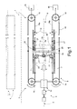
- Number 1 on Figure 1 indicates as a whole a cableway system with supporting and haul cables.
- System 1 may be used on its own to form a single cable track 2, or, conveniently, alongside an identical cableway system 1 to form a two-cable tracks, i.e. to and fro cableway system 3 only shown partly in Figure 1 .
- System 1 comprises a drive station 5; a return station 6; two parallel supporting cables 7 spaced a given distance apart and secured at one end at drive station 5, and at the other end at return station 6; a known trolley 8 fitted to supporting cables 7 ( Figures 1 and 3 ); a passenger car 8a suspended from trolley 8; and a haul-cable actuating unit 9 for moving trolley 8 in opposite directions along supporting cables 7.
- Actuating unit 9 comprises a known motor reducer 10 at drive station 5; and a haul-cable drive 12 interposed between trolley 8 and motor reducer 10.
- haul-cable drive 12 comprises two drive pulleys 14 located at drive station 5 and connected in known manner to motor reducer 10; two return pulleys 15 located at return station 6, and each connected to a respective counterweight 16 for moving the respective return pulley 15 away from the corresponding drive pulley 14; an open haul cable 18 wound about the two drive pulleys 14 and the two return pulleys 15, as shown in Figure 1 ; and two connecting devices 19 and 20 fitted to trolley 8 to connect haul cable 18 to trolley 8.
- Device 19 is located on the side of trolley 8 facing drive pulleys 14, and comprises two idle pulleys 21 fitted in fixed positions and in rotary manner to trolley 8, and about which winds a continuous intermediate portion 22 of haul cable 18 extending between drive pulleys 14. In actual use, idle pulleys 21 permit relative movement of intermediate portion 22 with respect to trolley 8.
- device 19 also comprises a known sense-pulley unit 24 located between idle pulleys 21 and comprising an idle pulley 25, which rotates about an axis parallel to those of idle pulleys 21, and is forced against portion 22 extending between pulleys 21, so as to curve part of portion 22 towards drive station 5.
- Unit 24 determines any variation in the tension of portion 22, and transmits a control signal to a known brake unit (not shown) for locking trolley 8 on haul cables 7.
- each idle pulley 21 is replaced by a respective number of side by side rollers with axes parallel to one another and to the axis of pulley 25, or by a slide member defining a curved slide and guide track, on which part of intermediate portion 22 slides.
- device 20 is a retaining device, by which the two free end portions 18a, 18b of haul cable 18 from return pulleys 15 are connected firmly to trolley 8 to prevent any relative movement between portions 18a, 18b and trolley 8.
- device 20 comprises, for each free end portion 18a, 18b, a joint 27 interposed between relative portion 18a, 18b and a bracket 28 fitted integrally to trolley 8.
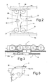
- device 20 comprises, for each end portion 18a, 18b, a respective drum 29, which is fitted integrally to trolley 8 with its axis conveniently parallel to those of pulleys 21 and 25, is located next to relative idle pulley 21, and is wound with an intermediate portion 29a of relative end portion 18a, 18b, the end portion 30 of which is secured to trolley 8 by a respective known clamp 31 not described in detail.
- Intermediate portions 29a are conveniently wound several times about respective drums 29 to form an "intermediate store" of standby cable for use during routine maintenance of system 1 ( Figure 3 ).
- each drum 29 is replaced by a respective fixed guide member 34, which is secured to trolley 8 and has a circumferential outer groove 35 ( figure 6 ) engaged by relative end portion 18a, 18b, an end portion of which is connected integrally to trolley 8 and to the end portion of the other portion 18a, 18b by a common clamp 36.
- the two free end portions of portions 18a, 18b are joined to form an endless cable, and clamp 36 secures the join or intermediate portions of portions 18a, 18b directly to trolley 8.
- clamp 36 is replaced by a drum 38 fixed to trolley 8, between guide members 34, and about which the joined end portions 18a, 18b are wound and conveniently secured to drum 38 by one or more dead turns of the cable.
- system 1 described provides, unlike the known solution, for fast, easy takeup of any variation in the length of the haul cable caused by settling of the cable or normal operation of the system.
- haul cable 18 is shortened by simply loosening and retightening clamps 31 and 36.
- haul cable 18 is shorted, in the Figure 1 solution, by simply remaking joints 27, and, in the Figure 2 and 5 solutions, by simply winding it about one or both of drums 29 and about drum 38 respectively.
- clamp 36 and drum 38 provide, when performing routine maintenance and, therefore, when the system is shut down, for sliding the cable easily with respect to trolley 8 and pulleys 14 and 15.
Landscapes
- Engineering & Computer Science (AREA)
- Transportation (AREA)
- Mechanical Engineering (AREA)
- Automation & Control Theory (AREA)
- Structural Engineering (AREA)
- Tents Or Canopies (AREA)
Priority Applications (2)
| Application Number | Priority Date | Filing Date | Title |
|---|---|---|---|
| EP07425837A EP2075172A1 (fr) | 2007-12-28 | 2007-12-28 | Système de transport à câble doté de câbles de support et d'un câble de traction séparé |
| US12/341,647 US20090165668A1 (en) | 2007-12-28 | 2008-12-22 | Cableway system with supporting and haul cables |
Applications Claiming Priority (1)
| Application Number | Priority Date | Filing Date | Title |
|---|---|---|---|
| EP07425837A EP2075172A1 (fr) | 2007-12-28 | 2007-12-28 | Système de transport à câble doté de câbles de support et d'un câble de traction séparé |
Publications (1)
| Publication Number | Publication Date |
|---|---|
| EP2075172A1 true EP2075172A1 (fr) | 2009-07-01 |
Family
ID=39427705
Family Applications (1)
| Application Number | Title | Priority Date | Filing Date |
|---|---|---|---|
| EP07425837A Withdrawn EP2075172A1 (fr) | 2007-12-28 | 2007-12-28 | Système de transport à câble doté de câbles de support et d'un câble de traction séparé |
Country Status (2)
| Country | Link |
|---|---|
| US (1) | US20090165668A1 (fr) |
| EP (1) | EP2075172A1 (fr) |
Cited By (1)
| Publication number | Priority date | Publication date | Assignee | Title |
|---|---|---|---|---|
| CN112277972A (zh) * | 2019-07-23 | 2021-01-29 | 波马公司 | 包括两个缆索环路之间的中继结构的索道设施 |
Families Citing this family (9)
| Publication number | Priority date | Publication date | Assignee | Title |
|---|---|---|---|---|
| ITBZ20030005A1 (it) * | 2003-01-30 | 2004-07-31 | High Technology Invest Bv | Dispositivo pressore per la conduzione di fune in sistemi di trasporto a trazione di fune. |
| ITBZ20050051A1 (it) * | 2005-09-29 | 2007-03-30 | High Technology Invest Bv | Dispositivo antiscarrucolamento per funi di impianti funiviari. |
| ITMI20070835A1 (it) * | 2007-04-20 | 2008-10-21 | Rolic Invest Sarl | Impianto di trasporto a fune e metodo di azionamento dello stesso |
| ITMI20070157U1 (it) * | 2007-04-20 | 2008-10-21 | Rolic Invest Sarl | Seggiovia |
| ITMI20071618A1 (it) * | 2007-08-03 | 2009-02-04 | Rolic Invest Sarl | Impianto di trasporto a fune e metodo di azionamento dello stesso |
| ITMI20072071A1 (it) * | 2007-10-26 | 2009-04-27 | Rolic Invest Sarl | Impianto di trasporto a fune e metodo di azionamento dello stesso |
| IT1395098B1 (it) | 2009-07-09 | 2012-09-05 | Rolic Invest Sarl | Unita' di trasporto per impianti di trasporto a fune |
| IT1395737B1 (it) * | 2009-08-04 | 2012-10-19 | Rolic Invest Sarl | Dispostivo di richiamo di un sedile per skilift |
| IT1401120B1 (it) | 2010-07-14 | 2013-07-12 | Rolic Invest Sarl | Scambio per impianto di trasporto a fune e impianto di trasporto a fune comprendente tale scambio. |
Citations (5)
| Publication number | Priority date | Publication date | Assignee | Title |
|---|---|---|---|---|
| DE475216C (de) * | 1927-04-23 | 1929-04-20 | August Hermes | Schraegaufzug mit Zweimotorenantrieb |
| AU408098B2 (en) * | 1965-05-14 | 1970-11-24 | Centine E. Blond Ins Crucianl | Improvements relating to cable-ways particularly to aerial transporting systems for excavating |
| DE2510671A1 (de) * | 1975-03-12 | 1976-09-23 | Bayerische Zugspitzbahn Ag | Zug- und gegenseilbefestigung an einem seilbahnfahrzeug |
| EP0692418A1 (fr) * | 1994-07-14 | 1996-01-17 | HOELZL COSTRUZIONE FUNIVIE s.r.l. | Dispositif de propulsion pour téléphériques ayant des câbles porteurs et des câbles tracteurs |
| WO2004094289A1 (fr) * | 2003-04-22 | 2004-11-04 | Otis Elevator Company | Systeme d'ascenseur sans contrepoids de deplacement |
Family Cites Families (16)
| Publication number | Priority date | Publication date | Assignee | Title |
|---|---|---|---|---|
| US472211A (en) * | 1892-04-05 | Half to louis a | ||
| CH563902A5 (fr) * | 1973-11-20 | 1975-07-15 | Habegger Willy | |
| JPS5599456A (en) * | 1979-01-25 | 1980-07-29 | Nissan Motor | Suspension mechanism of aerial track car |
| DE3109944C2 (de) * | 1981-03-14 | 1984-02-02 | PHB Weserhütte AG, 5000 Köln | Kuppelbare Umlauf-Drahtseilbahn zur Beförderung von Material, wie Schüttgut |
| FR2604675B1 (fr) * | 1986-10-02 | 1988-12-30 | Pomagalski Sa | Installation de transport aerien a deux cables porteurs-tracteurs a poulies decalees |
| FR2612144B1 (fr) * | 1987-03-11 | 1991-09-06 | Pomagalski Sa | Installation de transport aerien a deux cables porteurs-tracteurs a poulies decalees verticalement |
| US5113768A (en) * | 1991-03-15 | 1992-05-19 | Brown Garrett W | Cable-suspended apparatus for supporting a stabilized camera assembly |
| CA2143504A1 (fr) * | 1994-03-11 | 1995-09-12 | Ernst Egli | Dispositif de guidage de cable pour transporteur aerien a cable, notamment sur un circuit ferme |
| IT1270234B (it) * | 1994-06-16 | 1997-04-29 | Leitner Spa | Impianto funicolare a rotaia e fune traente, in particolare per il trasporto urbano, del tipo in cui i veicoli sono dotati di morsa a ganasce mobili per l'agganciamento/sganciamento da detta fune traente |
| AU1138799A (en) * | 1997-11-26 | 1999-06-16 | Litens Automotive Partnership | Load sensor |
| IT1310249B1 (it) * | 1999-09-24 | 2002-02-11 | Leitner Spa | Rulliera a doppio effetto per sostegni d'impianti a monofune, inparticolare seggiovie e cabinovie. |
| IT1316116B1 (it) * | 2000-01-21 | 2003-03-28 | Leitner Spa | Dispositivo per la impostazione e regolazione automatica della forzadi trazione di una fune di un verricello sopratesta per una macchina |
| IT1316149B1 (it) * | 2000-11-27 | 2003-03-28 | High Technology Invest Bv | Impianto di trasporto a trazione di fune mossa continua con veicolidotati di morse di agganciamento disimpegnabile. |
| ITBZ20030050A1 (it) * | 2003-10-03 | 2005-04-04 | High Technology Invest Bv | Smorzatore per funi traenti di funivie. |
| ITMI20050800A1 (it) * | 2005-05-03 | 2006-11-04 | Ferruccio Levi | Sistema di movimentazione per impianto funiviario comprendente due funi traenri |
| US7410068B1 (en) * | 2007-07-06 | 2008-08-12 | Agudio S.P.A. | Blondin cableway installation |
-
2007
- 2007-12-28 EP EP07425837A patent/EP2075172A1/fr not_active Withdrawn
-
2008
- 2008-12-22 US US12/341,647 patent/US20090165668A1/en not_active Abandoned
Patent Citations (6)
| Publication number | Priority date | Publication date | Assignee | Title |
|---|---|---|---|---|
| DE475216C (de) * | 1927-04-23 | 1929-04-20 | August Hermes | Schraegaufzug mit Zweimotorenantrieb |
| AU408098B2 (en) * | 1965-05-14 | 1970-11-24 | Centine E. Blond Ins Crucianl | Improvements relating to cable-ways particularly to aerial transporting systems for excavating |
| DE2510671A1 (de) * | 1975-03-12 | 1976-09-23 | Bayerische Zugspitzbahn Ag | Zug- und gegenseilbefestigung an einem seilbahnfahrzeug |
| EP0692418A1 (fr) * | 1994-07-14 | 1996-01-17 | HOELZL COSTRUZIONE FUNIVIE s.r.l. | Dispositif de propulsion pour téléphériques ayant des câbles porteurs et des câbles tracteurs |
| EP0692418B1 (fr) | 1994-07-14 | 1999-11-24 | HOELZL COSTRUZIONE FUNIVIE s.r.l. | Dispositif de propulsion pour téléphériques ayant des câbles porteurs et des câbles tracteurs |
| WO2004094289A1 (fr) * | 2003-04-22 | 2004-11-04 | Otis Elevator Company | Systeme d'ascenseur sans contrepoids de deplacement |
Cited By (2)
| Publication number | Priority date | Publication date | Assignee | Title |
|---|---|---|---|---|
| CN112277972A (zh) * | 2019-07-23 | 2021-01-29 | 波马公司 | 包括两个缆索环路之间的中继结构的索道设施 |
| CN112277972B (zh) * | 2019-07-23 | 2024-05-10 | 波马公司 | 包括两个缆索环路之间的中继结构的索道设施 |
Also Published As
| Publication number | Publication date |
|---|---|
| US20090165668A1 (en) | 2009-07-02 |
Similar Documents
| Publication | Publication Date | Title |
|---|---|---|
| US20090165668A1 (en) | Cableway system with supporting and haul cables | |
| RU2421355C2 (ru) | Устройство для накопления транспортных средств подвесной канатной дороги в накопительной зоне | |
| CN101195436B (zh) | 快速更换带式输送机胶带的方法 | |
| IT201900001841A1 (it) | Macchina di recupero di un cavo | |
| RU2008136536A (ru) | Канатная подвесная дорога с тягово-несущим канатом | |
| US11097750B2 (en) | Cable transportation system and method for transporting people or goods and clamp for a vehicle of a cable transportation system | |
| CN110775076B (zh) | 缆索运输系统 | |
| CZ34898A3 (cs) | Po koleji pojízdný stroj pro pokládání trolejového drátu | |
| AU2007237236A1 (en) | An aerial cableway | |
| CN107792085B (zh) | 一种吊厢式滑车轨道变轨机构及索道网系统 | |
| DE502006007190D1 (de) | Seilentgleisungsschutzvorrichtung für trag-/zugseile von seilbahnanlagen | |
| JP2001510270A (ja) | 案内チャネル構造 | |
| CN101503143B (zh) | 一种带式输送机胶带的安装装置及安装方法 | |
| KR101505795B1 (ko) | 케이블 포설 장치 | |
| BG61030B1 (bg) | Устройство за прокарване на проводник, въже или други подобни | |
| CN101807787B (zh) | 无动力恒长度线缆牵引机构 | |
| US12617655B2 (en) | Elevator system | |
| EP4497711A1 (fr) | Système feston pour le montage de câbles | |
| JP2023180625A (ja) | 索条のスプライス部検出装置 | |
| US8899157B2 (en) | Aerial transport installation with back-and-forth movement and multiple sections | |
| EP2555365B1 (fr) | Dispositif de serrage avec bloc de sécurité télescopique pour la tension d'une caténaire | |
| CN214362941U (zh) | 悬索桥猫道载人轨道系统 | |
| EP2028075B1 (fr) | Chariot de secours pour le sauvetage et le transport d'unités de transport d'un système de transport de câbles | |
| RU85875U1 (ru) | Устройство для перемещения железнодорожных вагонов | |
| CZ284723B6 (cs) | Zařízení pro eliminaci odchylek |
Legal Events
| Date | Code | Title | Description |
|---|---|---|---|
| PUAI | Public reference made under article 153(3) epc to a published international application that has entered the european phase |
Free format text: ORIGINAL CODE: 0009012 |
|
| AK | Designated contracting states |
Kind code of ref document: A1 Designated state(s): AT BE BG CH CY CZ DE DK EE ES FI FR GB GR HU IE IS IT LI LT LU LV MC MT NL PL PT RO SE SI SK TR |
|
| AX | Request for extension of the european patent |
Extension state: AL BA HR MK RS |
|
| 17P | Request for examination filed |
Effective date: 20091230 |
|
| 17Q | First examination report despatched |
Effective date: 20100201 |
|
| AKX | Designation fees paid |
Designated state(s): AT BE BG CH CY CZ DE DK EE ES FI FR GB GR HU IE IS IT LI LT LU LV MC MT NL PL PT RO SE SI SK TR |
|
| STAA | Information on the status of an ep patent application or granted ep patent |
Free format text: STATUS: THE APPLICATION IS DEEMED TO BE WITHDRAWN |
|
| 18D | Application deemed to be withdrawn |
Effective date: 20100812 |