EP2075383A2 - Dispositif de liaison de composants - Google Patents
Dispositif de liaison de composants Download PDFInfo
- Publication number
- EP2075383A2 EP2075383A2 EP08022473A EP08022473A EP2075383A2 EP 2075383 A2 EP2075383 A2 EP 2075383A2 EP 08022473 A EP08022473 A EP 08022473A EP 08022473 A EP08022473 A EP 08022473A EP 2075383 A2 EP2075383 A2 EP 2075383A2
- Authority
- EP
- European Patent Office
- Prior art keywords
- component
- base body
- holes
- cylindrical base
- axes
- Prior art date
- Legal status (The legal status is an assumption and is not a legal conclusion. Google has not performed a legal analysis and makes no representation as to the accuracy of the status listed.)
- Withdrawn
Links
- 239000007769 metal material Substances 0.000 claims description 2
- 239000002023 wood Substances 0.000 abstract description 12
- 238000004519 manufacturing process Methods 0.000 description 8
- 229910052751 metal Inorganic materials 0.000 description 5
- 239000002184 metal Substances 0.000 description 5
- 239000000725 suspension Substances 0.000 description 5
- 238000011161 development Methods 0.000 description 3
- 230000018109 developmental process Effects 0.000 description 3
- 230000000007 visual effect Effects 0.000 description 3
- 229910000831 Steel Inorganic materials 0.000 description 2
- 238000013459 approach Methods 0.000 description 2
- 238000005553 drilling Methods 0.000 description 2
- 230000000694 effects Effects 0.000 description 2
- 239000000463 material Substances 0.000 description 2
- 238000000034 method Methods 0.000 description 2
- 239000004033 plastic Substances 0.000 description 2
- 229920003023 plastic Polymers 0.000 description 2
- 238000002360 preparation method Methods 0.000 description 2
- 230000000087 stabilizing effect Effects 0.000 description 2
- 239000010959 steel Substances 0.000 description 2
- 238000010521 absorption reaction Methods 0.000 description 1
- 230000001154 acute effect Effects 0.000 description 1
- 229910052782 aluminium Inorganic materials 0.000 description 1
- XAGFODPZIPBFFR-UHFFFAOYSA-N aluminium Chemical compound [Al] XAGFODPZIPBFFR-UHFFFAOYSA-N 0.000 description 1
- 238000005266 casting Methods 0.000 description 1
- 210000000078 claw Anatomy 0.000 description 1
- 150000001875 compounds Chemical class 0.000 description 1
- 239000004567 concrete Substances 0.000 description 1
- 238000005520 cutting process Methods 0.000 description 1
- 238000013461 design Methods 0.000 description 1
- 238000004512 die casting Methods 0.000 description 1
- 238000009826 distribution Methods 0.000 description 1
- 238000000605 extraction Methods 0.000 description 1
- 239000000835 fiber Substances 0.000 description 1
- 238000009434 installation Methods 0.000 description 1
- 238000003754 machining Methods 0.000 description 1
- 229910001092 metal group alloy Inorganic materials 0.000 description 1
- 150000002739 metals Chemical class 0.000 description 1
- 238000003801 milling Methods 0.000 description 1
- 238000012545 processing Methods 0.000 description 1
- 238000005245 sintering Methods 0.000 description 1
- 230000006641 stabilisation Effects 0.000 description 1
- 238000011105 stabilization Methods 0.000 description 1
- 239000010935 stainless steel Substances 0.000 description 1
- 229910001220 stainless steel Inorganic materials 0.000 description 1
Images



Classifications
-
- E—FIXED CONSTRUCTIONS
- E04—BUILDING
- E04B—GENERAL BUILDING CONSTRUCTIONS; WALLS, e.g. PARTITIONS; ROOFS; FLOORS; CEILINGS; INSULATION OR OTHER PROTECTION OF BUILDINGS
- E04B1/00—Constructions in general; Structures which are not restricted either to walls, e.g. partitions, or floors or ceilings or roofs
- E04B1/18—Structures comprising elongated load-supporting parts, e.g. columns, girders, skeletons
- E04B1/26—Structures comprising elongated load-supporting parts, e.g. columns, girders, skeletons the supporting parts consisting of wood
- E04B1/2604—Connections specially adapted therefor
Definitions
- the invention relates to a device for connecting components, in particular wooden components, according to the preamble of claim 1.
- Components that allow a frontal connection are, for example, from DE 298 16 981 U1
- the axes of the fastening means are in this case arranged at a defined angle to the fiber direction of the wood; the larger this angle, the better.
- the nature of the design has some disadvantages: with an arrangement of the fasteners with pointing in the direction of the core of the timber carrier, conically converging axes, one is limited in the length of the fasteners: With a desirable large inclination angle of the axes, the fasteners must be correspondingly short, so that their ends do not touch each other, and the wood would locally weaken in its strength. Longer fasteners must be inserted at a shallower angle, which is at the expense of pull-out strength.
- the EP 1 122 372 A1 describes a solution for connecting two components by means of a hidden connecting element.
- the connecting element is sunk in one of the two parts and fastened with screws, nails or other suitable pin-shaped fastening means.
- a receptacle for a threaded rod or the like is provided along the longitudinal axis of the connecting element.
- the fastening means point only in the direction of the surface of the component (wood carrier or the like).
- the preparation of the receiving opening for the connecting element requires at least one blind hole with at least one step, which requires an increased effort in the production, or at least one adapted to the shape of the connecting element drilling tool.
- the invention has for its object to provide a device for connecting components, in particular wooden components, available, which allows a simple and secure attachment and can carry high loads at different types of stress.
- the object is achieved according to the invention in that the axes of the through holes for receiving fasteners are skewed and / or arranged parallel to each other.
- a "skewed" arrangement of the axes is present when they are neither intersecting nor parallel to each other.
- the main body preferably has a cylindrical shape
- the basic geometry of the substantially cylindrical base body may be a circle, since shapes based on circles can be produced easily by machine and also further processing is possible.
- rectangular or square (prismatic) basic shapes are also possible, since this is often necessary for the visual appearance.
- the geometry of the main body can also be designed such that it forms a positive connection with a main body of another device for connecting components, whereby such devices can be used as a suspension system.
- a further development of the invention can provide an efficiency-increasing manner in that the support element comprises a substantially cylindrical base body.
- the axes of the through holes in the direction of the lateral surface of the component to which the device is attached, and / or extend in the direction of the component core.
- the axes of the through holes can be arranged at an angle of 20 ° to 70 ° relative to the contact plane of the preferably cylindrical base body with the component. This angle may be the same for all fasteners in the device, but it may vary.
- a uniform application of force and a pleasing visual appearance of the device can be achieved by the intersections of the axes of the through holes are arranged with the contact plane of the preferably cylindrical base body with the component on at least one lying in said contact plane circular arc whose center is formed by the intersection of the axis of the preferably cylindrical body with said contact plane.
- At least one support element may be provided, which is positively or non-positively connectable with a provided on the first component, or molded connecting means.
- This connecting means may for example have a bore and / or an annular groove.
- a constructive embodiment of the invention can provide that the support element is integrally formed with the preferably cylindrical base body. This provides effective support against all forces and moments.
- the support member comprises a substantially annular base body.
- a simple assembly of the device can be achieved by the easy to manufacture, preferably cylindrical opening. Supporting the support element on the wall of the preferably cylindrical opening allows effective transverse force absorption.
- the substantially annular base body of the support element is arranged coaxially to the preferably cylindrical base body.
- the support element is a substantially cylindrical Base body has. This ensures easy installation of the device, in addition, a simple manufacturability of a cylindrical body is advantageous.
- the support member may comprise a frusto-conical base body, or a combination of truncated cone and cylinder.
- a simple manufacture of the device and a uniform recording of any transverse forces can be ensured by the substantially cylindrical base body of the support element is arranged coaxially with the preferably cylindrical base body.
- the mounting device has at least one bore with an internal thread. This allows easy attachment of different connection parts, such as threaded rods, various positive connection elements for suspension systems, claws and the like.
- the mounting device has at least one positive connection element.
- positive connection element can be, for example, hooks and / or eyelets, which can form a suspension system in combination.
- the bore associated with the mounting device extends into or through the substantially cylindrical base body of the support element.
- the fastening means are sunk flush when mounting the device to the component in the surface of the substantially cylindrical base body, it can be provided that the preferably cylindrical base body on the base facing away from the component frustoconical mouth openings of the through holes. These frusto-conical mouth openings can simultaneously serve as an approach for the preparation of the through holes.
- a particularly preferred development of the invention provides, in a cost-saving manner, that the fastening means have screws and / or pins. Using standard parts is preferable to save costs.
- the preferably cylindrical base body and / or the mounting device and / or the support element is made of metallic materials. Suitable for this purpose are, for example, steel, stainless steel, aluminum and other light metal alloys. In addition to machining, for example, non-cutting methods such as casting, die casting or sintering are possible.
- FIG. 1 illustrated embodiment of the invention shows a device 1 for connecting timber components.
- the cylindrical base body 2 and the cylindrical support member 7 here form a structural unit, the production is carried out by turning, the material is steel.
- a production of the device according to the invention made of plastic with inserts made of metal. In this way, the production can be carried out inexpensively, while the required strength is ensured by the metal parts.
- the through holes 3 for receiving the fastening means 4 are skewed to each other or arranged in parallel in the base body 2, so that there is no overlap of the longitudinal axes of the fastening means 4 in the three-dimensional space.
- the base body 2 is on the base surface facing away from the component 5 with frustoconical mouth openings 10 of the through holes 3 provided.
- These orifices 10 are made by milling and are used in production at the same time as an approach for drilling the through holes 3.
- a fastener 4 screws are excellent. It is also conceivable use of pins or nails.
- This spatial arrangement of the through-holes 3 allows the use of a large number of screws. This makes it possible to transmit large forces and to create a secure connection for different types of stress, especially when attached to the front of a wooden beam.
- the through holes 3 are mounted in at least two different distances from the axis of rotation of the main body 2. However, it is possible to select any number of different spacings, especially in devices 1 for connecting large-dimensioned wooden components, as a result of which fastening means 4 arranged in multiple skews with respect to one another are located in the wooden component 5.
- the support member 7 is connected during attachment to a formed on the component 5 connecting means 14.
- the connecting means 14 is a blind hole.
- This connecting means 14 fulfills several functions: Already during the fastening process it has a stabilizing and precision-increasing effect, since the transverse forces occurring during fastening are absorbed and there can be no change in position. The lateral forces occurring in later operation are also effectively absorbed.
- a further stabilizing effect results for the mounting device 6:
- This comprises a through hole passing through the support element 7 and the main body 2 with internal thread 6.
- This allows the attachment of a connecting element such as a threaded rod 12 for connection to another component.
- the rigid connection of body 2 and support member 7 in conjunction with the length of the through hole with internal thread 8 offers a high tensile strength and at the same time a high tilt stability of the device.
- a plurality of devices 1 can be arranged side by side, one above the other or offset, whereby the transmittable force is increased accordingly.
- the cylindrical support member 7 may have a chamfer or a Kantenverrundung, this facilitates assembly.
- FIG. 2 shows an oblique view of an embodiment of the device according to the invention with located in the through holes wood screws 4 with countersunk head.
- FIG. 3 1 is an oblique view of an embodiment of the device according to the invention attached to a wooden component 5.
- FIG. 4 illustrated embodiment of the invention shows a device 1 for connecting wood components with an annular support member 7.
- the support member 7 has a chamfer or a Kantenverrundung, whereby the assembly is much easier.
- This embodiment is a rotary part made of metal.
- the support element 7 engages in the formed on the component 5 connecting element 14, which has an annular groove substantially.
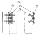
- FIG. 5 shows an embodiment of the invention with parallelepiped basic body 2 and form-locking connecting elements 11.
- This device 1 can be mounted, for example, on the front side of a wooden support 5.
- This wooden support can be subsequently connected to a second component, which has the counterparts to the provided on the device 1 connecting elements. In this way, can easily implement a suspension system.
- a special feature of this exemplary device is that due to a symmetry with respect to two axes of the device 1, the axes of the respective opposing screws 4 each other to cut. However, the point of intersection lies outside of the component 5.
- FIG. 6 shows an embodiment of the device 1 according to the invention with cylindrical support member 7, mounted on a component 5, with column base (12, 13).
- the component 5 has as a connecting means on a blind bore 14 which receives the support member 7 and the threaded rod 12.
- the column foot is formed by the threaded rod 12, which is firmly connected to the base plate 13.
Landscapes
- Engineering & Computer Science (AREA)
- Architecture (AREA)
- Physics & Mathematics (AREA)
- Electromagnetism (AREA)
- Civil Engineering (AREA)
- Structural Engineering (AREA)
- Joining Of Building Structures In Genera (AREA)
Applications Claiming Priority (1)
| Application Number | Priority Date | Filing Date | Title |
|---|---|---|---|
| AT21242007A AT506192B1 (de) | 2007-12-28 | 2007-12-28 | Verbindungselement |
Publications (2)
| Publication Number | Publication Date |
|---|---|
| EP2075383A2 true EP2075383A2 (fr) | 2009-07-01 |
| EP2075383A3 EP2075383A3 (fr) | 2011-12-14 |
Family
ID=40473627
Family Applications (1)
| Application Number | Title | Priority Date | Filing Date |
|---|---|---|---|
| EP08022473A Withdrawn EP2075383A3 (fr) | 2007-12-28 | 2008-12-27 | Dispositif de liaison de composants |
Country Status (2)
| Country | Link |
|---|---|
| EP (1) | EP2075383A3 (fr) |
| AT (1) | AT506192B1 (fr) |
Cited By (1)
| Publication number | Priority date | Publication date | Assignee | Title |
|---|---|---|---|---|
| EP4464852A1 (fr) | 2023-05-16 | 2024-11-20 | Hilti Aktiengesellschaft | Structure de construction en bois |
Families Citing this family (1)
| Publication number | Priority date | Publication date | Assignee | Title |
|---|---|---|---|---|
| DE102015224116A1 (de) | 2015-12-02 | 2017-06-08 | Universität Innsbruck | Verbindungsvorrichtung zum auflagern eines holzbauelements |
Citations (3)
| Publication number | Priority date | Publication date | Assignee | Title |
|---|---|---|---|---|
| DE29816981U1 (de) | 1998-09-22 | 1999-01-07 | Bohrenkämper, Gustav, 32257 Bünde | An einer Stirnseite eines Holzträgers befestigter Stützfuß |
| EP1122372A1 (fr) | 2000-02-07 | 2001-08-08 | Simpson Strong-Tie Co., Inc. | Connecteur caché |
| WO2006085078A1 (fr) | 2005-02-10 | 2006-08-17 | Timberfix Limited | Appareil pour fixer des poutres a des poteaux la structure d'une construction |
Family Cites Families (5)
| Publication number | Priority date | Publication date | Assignee | Title |
|---|---|---|---|---|
| US5419538A (en) * | 1994-03-18 | 1995-05-30 | Nicholson; Thomas N. | Newel post fastening system |
| US6015138A (en) * | 1996-12-12 | 2000-01-18 | Kohlberger; Walter | Newel post anchoring device |
| DE10051793A1 (de) * | 1999-10-18 | 2001-05-31 | Bulldog Simpson Gmbh | Holzverbinder sowie Zuschnitt für sein Blechformteil |
| DE10036754C1 (de) * | 2000-07-28 | 2002-06-13 | Gustav Bohrenkaemper | Verbindungsvorrichtung für zwei Bauteile |
| EP1690990A2 (fr) * | 2005-02-09 | 2006-08-16 | SFS intec Holding AG | Assemblage de montants et de traverses formés de poutres ou de lattes en bois pour la construction d'éléments de murs |
-
2007
- 2007-12-28 AT AT21242007A patent/AT506192B1/de not_active IP Right Cessation
-
2008
- 2008-12-27 EP EP08022473A patent/EP2075383A3/fr not_active Withdrawn
Patent Citations (3)
| Publication number | Priority date | Publication date | Assignee | Title |
|---|---|---|---|---|
| DE29816981U1 (de) | 1998-09-22 | 1999-01-07 | Bohrenkämper, Gustav, 32257 Bünde | An einer Stirnseite eines Holzträgers befestigter Stützfuß |
| EP1122372A1 (fr) | 2000-02-07 | 2001-08-08 | Simpson Strong-Tie Co., Inc. | Connecteur caché |
| WO2006085078A1 (fr) | 2005-02-10 | 2006-08-17 | Timberfix Limited | Appareil pour fixer des poutres a des poteaux la structure d'une construction |
Cited By (2)
| Publication number | Priority date | Publication date | Assignee | Title |
|---|---|---|---|---|
| EP4464852A1 (fr) | 2023-05-16 | 2024-11-20 | Hilti Aktiengesellschaft | Structure de construction en bois |
| WO2024235651A1 (fr) | 2023-05-16 | 2024-11-21 | Hilti Aktiengesellschaft | Structure de bâtiment en bois |
Also Published As
| Publication number | Publication date |
|---|---|
| EP2075383A3 (fr) | 2011-12-14 |
| AT506192B1 (de) | 2011-01-15 |
| AT506192A1 (de) | 2009-07-15 |
Similar Documents
| Publication | Publication Date | Title |
|---|---|---|
| EP3114359B1 (fr) | Dispositif servant à assembler un élément de structure à un élément de maintien selon un espacement l'un par rapport à l'autre | |
| EP0237768B1 (fr) | Dispositif d'assemblage spatial d'éléments | |
| EP1977124B1 (fr) | Dispositif pour maintenir et positionner des appareils, des pièces et des outils | |
| EP3047159B1 (fr) | Raccord de profilés et assemblage de profilés | |
| EP3199824A1 (fr) | Système de fixation et son utilisation | |
| EP2075383A2 (fr) | Dispositif de liaison de composants | |
| EP0078048B1 (fr) | Elément d'assemblage à jonction détachable pour barres, tuyaux de gauche ou parallèles ou pour éléments analogues | |
| DE10156731B4 (de) | Profilstab-Verbinder und Verfahren zum Verbinden von Profilstäben | |
| EP1903219B1 (fr) | Dispositif pour la fixation d'un composant sur un élément de support | |
| EP2092846B1 (fr) | Table | |
| DE202010006027U1 (de) | Abstützvorrichtung für Maschinenfüße | |
| EP3888497A1 (fr) | Dispositif de fixation d'un meuble à un support et procédé de fixation d'un corps de meuble à un support | |
| DE10352992B4 (de) | Holzverbinder | |
| EP3792506A1 (fr) | Raccord angulaire pouvant être réglé et fixé de manière variable | |
| EP1582802A1 (fr) | Dispositif de fixation pour écran plat | |
| EP1605172B1 (fr) | Ferrure pour assembler un élément structural allongé et un élément structural plat | |
| EP2394790A2 (fr) | Mors de rechange pour un étau | |
| EP3748170B1 (fr) | Système de fixation pour une plaque, un mur ou analogues | |
| EP1081392A2 (fr) | Ferrure d'assemblage pour le verrouillage de deux éléments | |
| DE60300443T2 (de) | Schraubenverbindung, insbesondere für geschlitzte Profilschienen | |
| DE4114458C1 (en) | Thin plate fastener with head member - which has plate abutting, flat, deposition surface and elongated arrester with dovetail shape | |
| AT503129A4 (de) | Verbindungsbeschlag für holzteile | |
| AT392129B (de) | Verankerungsbeschlag fuer schraubverbindungen fuer rechtwinkelig zueinander stehende moebelbauplatten | |
| DE102007023990A1 (de) | Verbindungselement für sich kreuzende Seite | |
| DE29819228U1 (de) | Verbindungselement für Bauteile und Verbindungsanordnung |
Legal Events
| Date | Code | Title | Description |
|---|---|---|---|
| PUAI | Public reference made under article 153(3) epc to a published international application that has entered the european phase |
Free format text: ORIGINAL CODE: 0009012 |
|
| AK | Designated contracting states |
Kind code of ref document: A2 Designated state(s): AT BE BG CH CY CZ DE DK EE ES FI FR GB GR HR HU IE IS IT LI LT LU LV MC MT NL NO PL PT RO SE SI SK TR |
|
| AX | Request for extension of the european patent |
Extension state: AL BA MK RS |
|
| PUAL | Search report despatched |
Free format text: ORIGINAL CODE: 0009013 |
|
| AK | Designated contracting states |
Kind code of ref document: A3 Designated state(s): AT BE BG CH CY CZ DE DK EE ES FI FR GB GR HR HU IE IS IT LI LT LU LV MC MT NL NO PL PT RO SE SI SK TR |
|
| AX | Request for extension of the european patent |
Extension state: AL BA MK RS |
|
| RIC1 | Information provided on ipc code assigned before grant |
Ipc: E04B 1/26 20060101AFI20111110BHEP |
|
| 17P | Request for examination filed |
Effective date: 20120511 |
|
| 17Q | First examination report despatched |
Effective date: 20120716 |
|
| AKX | Designation fees paid |
Designated state(s): AT BE BG CH CY CZ DE DK EE ES FI FR GB GR HR HU IE IS IT LI LT LU LV MC MT NL NO PL PT RO SE SI SK TR |
|
| 17Q | First examination report despatched |
Effective date: 20120820 |
|
| RAP1 | Party data changed (applicant data changed or rights of an application transferred) |
Owner name: BAESSLER, UWE |
|
| RIN1 | Information on inventor provided before grant (corrected) |
Inventor name: BAESSLER, UWE |
|
| RAP1 | Party data changed (applicant data changed or rights of an application transferred) |
Owner name: BAESSLER, UWE |
|
| RIN1 | Information on inventor provided before grant (corrected) |
Inventor name: BAESSLER, UWE |
|
| STAA | Information on the status of an ep patent application or granted ep patent |
Free format text: STATUS: THE APPLICATION IS DEEMED TO BE WITHDRAWN |
|
| 18D | Application deemed to be withdrawn |
Effective date: 20130302 |