EP2075419A2 - Système d'alimentation en huile de turbines à gaz ainsi que procédé de fonctionnement d'une alimentation d'huile de stockage de turbines à gaz - Google Patents
Système d'alimentation en huile de turbines à gaz ainsi que procédé de fonctionnement d'une alimentation d'huile de stockage de turbines à gaz Download PDFInfo
- Publication number
- EP2075419A2 EP2075419A2 EP08021199A EP08021199A EP2075419A2 EP 2075419 A2 EP2075419 A2 EP 2075419A2 EP 08021199 A EP08021199 A EP 08021199A EP 08021199 A EP08021199 A EP 08021199A EP 2075419 A2 EP2075419 A2 EP 2075419A2
- Authority
- EP
- European Patent Office
- Prior art keywords
- oil
- gas turbine
- pump
- oil pump
- oil supply
- Prior art date
- Legal status (The legal status is an assumption and is not a legal conclusion. Google has not performed a legal analysis and makes no representation as to the accuracy of the status listed.)
- Withdrawn
Links
Images
Classifications
-
- F—MECHANICAL ENGINEERING; LIGHTING; HEATING; WEAPONS; BLASTING
- F01—MACHINES OR ENGINES IN GENERAL; ENGINE PLANTS IN GENERAL; STEAM ENGINES
- F01D—NON-POSITIVE DISPLACEMENT MACHINES OR ENGINES, e.g. STEAM TURBINES
- F01D25/00—Component parts, details, or accessories, not provided for in, or of interest apart from, other groups
- F01D25/18—Lubricating arrangements
-
- B—PERFORMING OPERATIONS; TRANSPORTING
- B42—BOOKBINDING; ALBUMS; FILES; SPECIAL PRINTED MATTER
- B42D—BOOKS; BOOK COVERS; LOOSE LEAVES; PRINTED MATTER CHARACTERISED BY IDENTIFICATION OR SECURITY FEATURES; PRINTED MATTER OF SPECIAL FORMAT OR STYLE NOT OTHERWISE PROVIDED FOR; DEVICES FOR USE THEREWITH AND NOT OTHERWISE PROVIDED FOR; MOVABLE-STRIP WRITING OR READING APPARATUS
- B42D15/00—Printed matter of special format or style not otherwise provided for
-
- F—MECHANICAL ENGINEERING; LIGHTING; HEATING; WEAPONS; BLASTING
- F01—MACHINES OR ENGINES IN GENERAL; ENGINE PLANTS IN GENERAL; STEAM ENGINES
- F01D—NON-POSITIVE DISPLACEMENT MACHINES OR ENGINES, e.g. STEAM TURBINES
- F01D25/00—Component parts, details, or accessories, not provided for in, or of interest apart from, other groups
- F01D25/18—Lubricating arrangements
- F01D25/20—Lubricating arrangements using lubrication pumps
-
- F—MECHANICAL ENGINEERING; LIGHTING; HEATING; WEAPONS; BLASTING
- F01—MACHINES OR ENGINES IN GENERAL; ENGINE PLANTS IN GENERAL; STEAM ENGINES
- F01M—LUBRICATING OF MACHINES OR ENGINES IN GENERAL; LUBRICATING INTERNAL COMBUSTION ENGINES; CRANKCASE VENTILATING
- F01M5/00—Heating, cooling, or controlling temperature of lubricant; Lubrication means facilitating engine starting
- F01M5/02—Conditioning lubricant for aiding engine starting, e.g. heating
- F01M5/021—Conditioning lubricant for aiding engine starting, e.g. heating by heating
-
- F—MECHANICAL ENGINEERING; LIGHTING; HEATING; WEAPONS; BLASTING
- F02—COMBUSTION ENGINES; HOT-GAS OR COMBUSTION-PRODUCT ENGINE PLANTS
- F02C—GAS-TURBINE PLANTS; AIR INTAKES FOR JET-PROPULSION PLANTS; CONTROLLING FUEL SUPPLY IN AIR-BREATHING JET-PROPULSION PLANTS
- F02C7/00—Features, components parts, details or accessories, not provided for in, or of interest apart form groups F02C1/00 - F02C6/00; Air intakes for jet-propulsion plants
- F02C7/06—Arrangements of bearings; Lubricating
-
- B—PERFORMING OPERATIONS; TRANSPORTING
- B42—BOOKBINDING; ALBUMS; FILES; SPECIAL PRINTED MATTER
- B42D—BOOKS; BOOK COVERS; LOOSE LEAVES; PRINTED MATTER CHARACTERISED BY IDENTIFICATION OR SECURITY FEATURES; PRINTED MATTER OF SPECIAL FORMAT OR STYLE NOT OTHERWISE PROVIDED FOR; DEVICES FOR USE THEREWITH AND NOT OTHERWISE PROVIDED FOR; MOVABLE-STRIP WRITING OR READING APPARATUS
- B42D25/00—Information-bearing cards or sheet-like structures characterised by identification or security features; Manufacture thereof
- B42D25/20—Information-bearing cards or sheet-like structures characterised by identification or security features; Manufacture thereof characterised by a particular use or purpose
- B42D25/28—Information-bearing cards or sheet-like structures characterised by identification or security features; Manufacture thereof characterised by a particular use or purpose for use in medical treatment or therapy
-
- F—MECHANICAL ENGINEERING; LIGHTING; HEATING; WEAPONS; BLASTING
- F01—MACHINES OR ENGINES IN GENERAL; ENGINE PLANTS IN GENERAL; STEAM ENGINES
- F01M—LUBRICATING OF MACHINES OR ENGINES IN GENERAL; LUBRICATING INTERNAL COMBUSTION ENGINES; CRANKCASE VENTILATING
- F01M1/00—Pressure lubrication
- F01M1/02—Pressure lubrication using lubricating pumps
- F01M2001/0207—Pressure lubrication using lubricating pumps characterised by the type of pump
- F01M2001/0215—Electrical pumps
Definitions
- the invention relates to a gas turbine oil supply system and a method of operating a gas turbine storage oil supply.
- Oil supply systems are known in the prior art, in which bearing oil for the turbine rotor is pumped by means of a mechanical pump from an oil tank to the camps.
- the mechanical pump is usually flanged to the transmission and is driven by one of the shafts of the gas turbine, usually the high-speed shaft.
- the operating rules require a pilot to significantly reduce the altitude to allow a gas turbine to restart that has only been rotated by the airstream for an extended period of time, such that the oil temperature has dropped below a threshold that allows a gas turbine start.
- the operating rules determine that even at an oil temperature above -40 ° C, it is not recommended to accelerate the gas turbine on the idle speed before the oil temperature reaches another limit, which is dictated by the operating rules and may depend on the type of gas turbine.
- the invention has for its object to provide a gas turbine oil supply system and a method for operating a bearing oil supply to a gas turbine, which enables effective heating of the oil while avoiding the disadvantages of the prior art.
- the invention thus provides that an electric oil pump is used.
- This electric oil pump is independent of the speed of the shaft of the gas turbine and allows pumping of the oil regardless of the speed of the gas turbine.
- the electric oil pump can thus be put into operation even when the gas turbine is stopped.
- the electric oil pump is used to recirculate the oil, which is pumped out of the oil tank via the supply line, and to pump it into the oil tank.
- damage to the oil pump with very viscous oil is not to be feared, since no further resistance is opposed.
- the cold oil is first pumped through the storage chambers.
- the inventive design it is thus possible to preheat the oil to allow a quick start of the gas turbine and thus to shorten the time to the start of the aircraft.
- the electric oil pump only electrical energy is needed to drive the electric oil pump.
- This electrical energy can be provided by an external power supply or by a simple generator. Due to the waste heat of the electric oil pump, the oil is additionally heated, in addition to the heating by the pressurization by the electric oil pump itself.
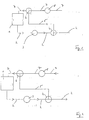
- the Fig. 1 and 2 show an oil tank 1, from which a supply line 2 branches off to pump oil to storage chambers, not shown.
- an electric oil pump 3 is arranged in the oil supply line 2, from which a supply line 2 branches off to pump oil to storage chambers, not shown.
- a first branch element 4 Downstream of the electric oil pump 3, a first branch element 4 is arranged (multi-way valve), which is externally controllable. From the first branch element 4 branches off a return line 5, which leads to a second branch element 6 (multi-way valve), which is arranged in a return line from the storage chambers to the oil tank 1.
- the reference numeral 8 shows a return pump 8, which can be operated electrically or mechanically.
- the Fig. 1 shows a state in which the oil is below a setpoint.
- the first branch element 4 switches the oil flow pumped by the electric oil pump so that it is pumped back through the return line 5 into the oil tank 6, the second branch element 6 also being in the recirculation position.
- Fig. 1 shown state is thus a state before the start of the gas turbine. In this case, no oil is supplied to the drive and bearing elements. Rather, the oil is merely pumped around to heat it.
- the inertia of the oil mass in the tank can prevent a rapid rise in temperature and heat dissipation by the electric oil pump.
- the branch elements 4 and 6 switch to the in Fig. 2 shown operating position. In this no oil is recirculated through the return line 5, but the entire oil flow is fed through the supply line 2 the storage chambers or other consumers and returned through the return line 7 (with the aid of the return pump 8). In this case, the warm-up time of the remaining oil in the oil system and in the storage chambers and the other consumers is significantly reduced by the large, stored in the oil tank 1 heated oil volume.
- the electric drive makes it possible to dispense with ground-based facilities.
- Another advantage is that the solution according to the invention is completely independent of the speed of the gas turbine shafts and thus can also be operated when the gas turbine is stationary and no oil flow to the bearings and other consumers is required.
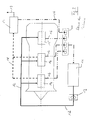
- the Fig. 3 shows an oil circuit according to the prior art.
- the outline of a gas turbine is shown schematically.
- This includes ventilated storage chambers 14 and an unvented storage chamber 15.
- the storage chambers 14 and 15 are supplied via an oil supply line 12, in which an oil pump 13 is provided with oil from an oil tank 11.
- oil pump 13 is provided with oil from an oil tank 11.
- return lines 16 the oil is conveyed back through a return pump 20 into the tank 11.
- vent lines 18 are connected to the bearing chambers 14 and 15, which deliver an oil-air mixture to a breather 17 (Breather). From this, the separated oil is passed via a return line 16 to the return pump 20, while air is discharged via an exhaust duct 19.
Landscapes
- Engineering & Computer Science (AREA)
- Mechanical Engineering (AREA)
- General Engineering & Computer Science (AREA)
- Chemical & Material Sciences (AREA)
- Combustion & Propulsion (AREA)
- Engine Equipment That Uses Special Cycles (AREA)
- Lubrication Of Internal Combustion Engines (AREA)
Applications Claiming Priority (1)
| Application Number | Priority Date | Filing Date | Title |
|---|---|---|---|
| DE102007058954A DE102007058954A1 (de) | 2007-12-07 | 2007-12-07 | Gasturbinenölversorgungssystem sowie Verfahren zum Betrieb einer Gasturbinen-Lager-Ölversorgung |
Publications (2)
| Publication Number | Publication Date |
|---|---|
| EP2075419A2 true EP2075419A2 (fr) | 2009-07-01 |
| EP2075419A3 EP2075419A3 (fr) | 2010-11-03 |
Family
ID=40266160
Family Applications (1)
| Application Number | Title | Priority Date | Filing Date |
|---|---|---|---|
| EP08021199A Withdrawn EP2075419A3 (fr) | 2007-12-07 | 2008-12-05 | Système d'alimentation en huile de turbines à gaz ainsi que procédé de fonctionnement d'une alimentation d'huile de stockage de turbines à gaz |
Country Status (3)
| Country | Link |
|---|---|
| US (1) | US8887869B2 (fr) |
| EP (1) | EP2075419A3 (fr) |
| DE (1) | DE102007058954A1 (fr) |
Cited By (1)
| Publication number | Priority date | Publication date | Assignee | Title |
|---|---|---|---|---|
| FR3058461A1 (fr) * | 2016-11-10 | 2018-05-11 | Safran Aircraft Engines | Circuit hydraulique a circuit de recirculation pilote |
Families Citing this family (16)
| Publication number | Priority date | Publication date | Assignee | Title |
|---|---|---|---|---|
| DE102008057828A1 (de) * | 2008-11-18 | 2010-05-20 | Rolls-Royce Deutschland Ltd & Co Kg | Fluggasturbinen-Ölsystemerwärmung |
| US9086018B2 (en) * | 2010-04-23 | 2015-07-21 | Hamilton Sundstrand Corporation | Starting a gas turbine engine to maintain a dwelling speed after light-off |
| EP2754908B1 (fr) * | 2013-01-10 | 2018-01-10 | GE Renewable Technologies | Systèmes de lubrification pour ensembles de paliers |
| US10329955B2 (en) | 2016-01-27 | 2019-06-25 | Pratt & Whitney Canada Corp. | Oil system for turbine engine and related method |
| US20170356304A1 (en) * | 2016-06-13 | 2017-12-14 | General Electric Company | Systems and methods for reducing fluid viscosity in a gas turbine engine |
| US10450894B2 (en) | 2016-11-28 | 2019-10-22 | United Technologies Corporation | Bearing compartment scavenge control |
| CN107246325B (zh) * | 2017-06-01 | 2023-08-11 | 中国船舶重工集团公司第七O三研究所无锡分部 | 一种多功能燃气轮机工作台滑油系统 |
| US10851941B2 (en) * | 2017-12-04 | 2020-12-01 | Rolls-Royce Corporation | Lubrication and scavenge system |
| GB2569783A (en) * | 2017-12-15 | 2019-07-03 | Airbus Operations Ltd | Hydraulic system characteristics |
| US11236672B2 (en) * | 2018-06-14 | 2022-02-01 | Raytheon Technologies Corporation | Oil thermal management system for cold weather operations of a gas turbine engine |
| US11492969B2 (en) | 2019-12-09 | 2022-11-08 | Meggitt Aerospace Limited | Engine thermal management methods and control systems |
| FR3112365B1 (fr) * | 2020-07-09 | 2022-07-29 | Safran Helicopter Engines | Procede de demarrage d’un moteur d’aeronef |
| US11994165B2 (en) | 2022-03-01 | 2024-05-28 | General Electric Company | Lubricant supply system |
| CN115163249B (zh) * | 2022-08-08 | 2023-06-02 | 中车资阳机车有限公司 | 一种内燃机车柴油机机油在线自动添加系统 |
| US12297758B2 (en) * | 2023-01-07 | 2025-05-13 | Pratt & Whitney Canada Corp. | Bypass valve |
| US20250109709A1 (en) * | 2023-10-03 | 2025-04-03 | Rtx Corporation | Electronically driven lubrication system on gas turbine engines |
Citations (4)
| Publication number | Priority date | Publication date | Assignee | Title |
|---|---|---|---|---|
| GB509238A (en) | 1937-10-12 | 1939-07-12 | Neil Shaw Muir | Improvements in means for heating liquids, for use in the operation of aircraft and for other purposes |
| DE2940643A1 (de) | 1979-10-06 | 1981-04-16 | Klöckner-Humboldt-Deutz AG, 5000 Köln | Einrichtung zum an- bzw. aufheizen von maschinen |
| JPS62176599U (fr) | 1986-04-30 | 1987-11-10 | ||
| EP1847698A1 (fr) | 2006-04-21 | 2007-10-24 | Pratt & Whitney Canada Corp. | Préchauffage d'un liquide dans un réservoir d'avion |
Family Cites Families (27)
| Publication number | Priority date | Publication date | Assignee | Title |
|---|---|---|---|---|
| US2402467A (en) * | 1944-01-31 | 1946-06-18 | Westinghouse Electric Corp | Lubrication control |
| US3451214A (en) * | 1967-03-15 | 1969-06-24 | Garrett Corp | Cold engine start facilitating apparatus |
| FR1594316A (fr) * | 1968-11-28 | 1970-06-01 | ||
| US3769790A (en) * | 1972-03-20 | 1973-11-06 | Gen Motors Corp | Gas turbine lubrication |
| FR2358615A1 (fr) | 1976-07-16 | 1978-02-10 | Snecma | Systeme de recuperation d'huile |
| US4284174A (en) | 1979-04-18 | 1981-08-18 | Avco Corporation | Emergency oil/mist system |
| US4441311A (en) * | 1982-05-13 | 1984-04-10 | United Technologies Corporation | Means for controlling the air scavenge pressure in the bearing compartment of a gas turbine engine |
| DE3242366C2 (de) * | 1982-11-16 | 1985-02-07 | MTU Motoren- und Turbinen-Union München GmbH, 8000 München | Ölversorgungseinrichtung für beliebigen Flugsituationen aussetzbare Gasturbinentriebwerke |
| JPH0667517B2 (ja) | 1986-01-29 | 1994-08-31 | 株式会社荏原製作所 | 有機性水溶液のメタン発酵法 |
| DE3605619A1 (de) | 1986-02-21 | 1987-08-27 | Mtu Muenchen Gmbh | Stroemungsmaschine mit versorgungseinrichtung fuer schmiermittel |
| JPS63297863A (ja) * | 1987-05-28 | 1988-12-05 | Fuji Heavy Ind Ltd | ロックアップトルコン付無段変速機の油圧制御装置 |
| US4940114A (en) * | 1989-09-05 | 1990-07-10 | Albrecht Kenneth D | Engine prelubricating system |
| NL9000860A (nl) * | 1990-04-12 | 1991-11-01 | Doornes Transmissie Bv | Elektronisch geregelde continu variabele transmissie. |
| GB2260577B (en) * | 1991-10-16 | 1994-10-05 | Rolls Royce Plc | Gas turbine engine starting |
| DE4304482A1 (de) | 1993-02-15 | 1994-08-18 | Abb Management Ag | Schmiersystem für eine Turbomaschine |
| JPH08285021A (ja) * | 1995-04-10 | 1996-11-01 | Unisia Jecs Corp | 無段変速機の制御装置 |
| JP3422227B2 (ja) * | 1997-07-16 | 2003-06-30 | 日産自動車株式会社 | 無段変速機の制御装置 |
| JP3152176B2 (ja) * | 1997-08-12 | 2001-04-03 | 日産自動車株式会社 | 無段変速機の変速制御装置 |
| US6367833B1 (en) * | 2000-09-13 | 2002-04-09 | Shimano, Inc. | Automatic shifting control device for a bicycle |
| JP2003120799A (ja) * | 2001-10-15 | 2003-04-23 | Shimano Inc | 自転車用変速制御装置 |
| JP3644633B2 (ja) * | 2001-11-21 | 2005-05-11 | 株式会社シマノ | 自転車用変速制御装置 |
| US7426834B2 (en) | 2004-02-03 | 2008-09-23 | General Electric Company | “Get home” oil supply and scavenge system |
| DE102005031804A1 (de) | 2005-07-07 | 2007-01-18 | Mtu Aero Engines Gmbh | Schmiermittelsystem |
| US7571597B2 (en) * | 2006-01-25 | 2009-08-11 | Honeywell International Inc. | Airframe mounted motor driven lubrication pump control system and method |
| US7836675B2 (en) | 2006-02-21 | 2010-11-23 | General Electric Company | Supercore sump vent pressure control |
| DE102006023580A1 (de) | 2006-05-19 | 2007-11-22 | Mtu Aero Engines Gmbh | Schmiermittelsystem |
| JP4690255B2 (ja) * | 2006-06-15 | 2011-06-01 | トヨタ自動車株式会社 | ベルト式無段変速機の制御装置 |
-
2007
- 2007-12-07 DE DE102007058954A patent/DE102007058954A1/de not_active Withdrawn
-
2008
- 2008-12-05 EP EP08021199A patent/EP2075419A3/fr not_active Withdrawn
- 2008-12-08 US US12/314,328 patent/US8887869B2/en active Active
Patent Citations (4)
| Publication number | Priority date | Publication date | Assignee | Title |
|---|---|---|---|---|
| GB509238A (en) | 1937-10-12 | 1939-07-12 | Neil Shaw Muir | Improvements in means for heating liquids, for use in the operation of aircraft and for other purposes |
| DE2940643A1 (de) | 1979-10-06 | 1981-04-16 | Klöckner-Humboldt-Deutz AG, 5000 Köln | Einrichtung zum an- bzw. aufheizen von maschinen |
| JPS62176599U (fr) | 1986-04-30 | 1987-11-10 | ||
| EP1847698A1 (fr) | 2006-04-21 | 2007-10-24 | Pratt & Whitney Canada Corp. | Préchauffage d'un liquide dans un réservoir d'avion |
Cited By (2)
| Publication number | Priority date | Publication date | Assignee | Title |
|---|---|---|---|---|
| FR3058461A1 (fr) * | 2016-11-10 | 2018-05-11 | Safran Aircraft Engines | Circuit hydraulique a circuit de recirculation pilote |
| US10920798B2 (en) | 2016-11-10 | 2021-02-16 | Safran Aircraft Engines | Hydraulic circuit with controlled recirculation circuit |
Also Published As
| Publication number | Publication date |
|---|---|
| US20100012434A1 (en) | 2010-01-21 |
| US8887869B2 (en) | 2014-11-18 |
| EP2075419A3 (fr) | 2010-11-03 |
| DE102007058954A1 (de) | 2009-06-10 |
Similar Documents
| Publication | Publication Date | Title |
|---|---|---|
| EP2075419A2 (fr) | Système d'alimentation en huile de turbines à gaz ainsi que procédé de fonctionnement d'une alimentation d'huile de stockage de turbines à gaz | |
| DE602004000889T2 (de) | Gasturbinentriebwerk und Lufteinlass für ein Gasturbinentriebwerk mit einer Vorrichtung zur Verhinderung von Vereisung | |
| DE102016204911A1 (de) | Flugzeugklimaanlage mit einem elektrisch angetriebenen Umgebungsluftkompressor und Verfahren zum Betreiben einer derartigen Flugzeugklimaanlage | |
| DE102006042584A1 (de) | Luftzufuhrsystem eines Flugzeuges sowie Verfahren zum Vermischen zweier Luftströme in einem Luftzufuhrsystem | |
| EP2824302B1 (fr) | Procédé et dispositif de transfert thermique pour un véhicule | |
| DE102004061372B4 (de) | Anordnung und Verfahren zur Abluftwärmenutzung zum Beheizen des Bilgebereiches von Flugzeugen | |
| EP2187003A2 (fr) | Système du chauffage d'huile pour turbines à gaz pour aéronef | |
| DE102012018712A1 (de) | Luftfördereinrichtung und Brennstoffzellensystem | |
| DE2946371C2 (de) | Hilfsantriebsanlage für Flugzeughilfsgeräte | |
| WO2018122297A1 (fr) | Système de propulsion électrique équipé d'un système à pression de gaz et d'un câble hybride | |
| DE102006060765B3 (de) | System und Verfahren zur Kühlung einer wärmebelasteten Einrichtung an Bord eines Flugzeugs | |
| DE2325592C2 (de) | Anordnung zum Anfahren von Flugzeuggasturbinentriebwerken und zum Betreiben von Flugzeughilfsgeräten | |
| DE102008018101A1 (de) | Strahltriebwerk mit mindestens einem Notantrieb | |
| EP0189875B1 (fr) | Système puissance auxiliaire pour un moteur turbine à gaz | |
| WO2017084791A1 (fr) | Production de vide pour dégazage de réservoir ou de servofrein | |
| DE102015209573A1 (de) | Schmiervorrichtung und Verfahren zum Schmieren eines Getriebes für eine Windkraftanlage | |
| EP4282017A2 (fr) | Dispositif de transport de milieux | |
| DE10142696B4 (de) | Beheizbares Anschlußrohrstück für eine Rohr- bzw. Schlauchleitung eines Drainage-, Frisch- sowie Grauwassersystem in einem Flugzeug | |
| DE102014009771A1 (de) | Kühlsystem für eine Brennstoffzelle | |
| DE102020127303B4 (de) | Kältemittelverdichter, Kraftfahrzeug und Verfahren zum Betreiben eines Kältemittelverdichters | |
| DE202009014270U1 (de) | Druckluftstartgerät für ein Luftfahrzeug | |
| EP2349831A2 (fr) | Dispositif de réglage d'une hélice d'avion | |
| DE102019202473A1 (de) | Getriebeanordnung für ein Kraftfahrzeug | |
| DE102025107731A1 (de) | Elektrifiziertes doppelpumpenkraftstoffsystem mit parallelisierung | |
| DE102016009562A1 (de) | Vorrichtung zur Bereitstellung von Gas |
Legal Events
| Date | Code | Title | Description |
|---|---|---|---|
| PUAI | Public reference made under article 153(3) epc to a published international application that has entered the european phase |
Free format text: ORIGINAL CODE: 0009012 |
|
| AK | Designated contracting states |
Kind code of ref document: A2 Designated state(s): AT BE BG CH CY CZ DE DK EE ES FI FR GB GR HR HU IE IS IT LI LT LU LV MC MT NL NO PL PT RO SE SI SK TR |
|
| AX | Request for extension of the european patent |
Extension state: AL BA MK RS |
|
| PUAL | Search report despatched |
Free format text: ORIGINAL CODE: 0009013 |
|
| AK | Designated contracting states |
Kind code of ref document: A3 Designated state(s): AT BE BG CH CY CZ DE DK EE ES FI FR GB GR HR HU IE IS IT LI LT LU LV MC MT NL NO PL PT RO SE SI SK TR |
|
| AX | Request for extension of the european patent |
Extension state: AL BA MK RS |
|
| RIC1 | Information provided on ipc code assigned before grant |
Ipc: F02C 7/06 20060101ALI20100924BHEP Ipc: F01M 5/02 20060101ALI20100924BHEP Ipc: F01D 25/18 20060101AFI20090129BHEP |
|
| 17P | Request for examination filed |
Effective date: 20101215 |
|
| AKX | Designation fees paid |
Designated state(s): DE FR GB |
|
| 17Q | First examination report despatched |
Effective date: 20170123 |
|
| STAA | Information on the status of an ep patent application or granted ep patent |
Free format text: STATUS: THE APPLICATION HAS BEEN WITHDRAWN |
|
| 18W | Application withdrawn |
Effective date: 20170410 |