EP2075497B1 - Verbindungsvorrichtung - Google Patents
Verbindungsvorrichtung Download PDFInfo
- Publication number
- EP2075497B1 EP2075497B1 EP06811642.5A EP06811642A EP2075497B1 EP 2075497 B1 EP2075497 B1 EP 2075497B1 EP 06811642 A EP06811642 A EP 06811642A EP 2075497 B1 EP2075497 B1 EP 2075497B1
- Authority
- EP
- European Patent Office
- Prior art keywords
- coupling
- fitting projections
- coupling apparatus
- apparatuses
- fitting
- Prior art date
- Legal status (The legal status is an assumption and is not a legal conclusion. Google has not performed a legal analysis and makes no representation as to the accuracy of the status listed.)
- Active
Links
Images








Classifications
-
- F—MECHANICAL ENGINEERING; LIGHTING; HEATING; WEAPONS; BLASTING
- F16—ENGINEERING ELEMENTS AND UNITS; GENERAL MEASURES FOR PRODUCING AND MAINTAINING EFFECTIVE FUNCTIONING OF MACHINES OR INSTALLATIONS; THERMAL INSULATION IN GENERAL
- F16L—PIPES; JOINTS OR FITTINGS FOR PIPES; SUPPORTS FOR PIPES, CABLES OR PROTECTIVE TUBING; MEANS FOR THERMAL INSULATION IN GENERAL
- F16L37/00—Couplings of the quick-acting type
- F16L37/08—Couplings of the quick-acting type in which the connection between abutting or axially overlapping ends is maintained by locking members
- F16L37/10—Couplings of the quick-acting type in which the connection between abutting or axially overlapping ends is maintained by locking members using a rotary external sleeve or ring on one part
- F16L37/113—Couplings of the quick-acting type in which the connection between abutting or axially overlapping ends is maintained by locking members using a rotary external sleeve or ring on one part the male part having lugs on its periphery penetrating into the corresponding slots provided in the female part
-
- F—MECHANICAL ENGINEERING; LIGHTING; HEATING; WEAPONS; BLASTING
- F16—ENGINEERING ELEMENTS AND UNITS; GENERAL MEASURES FOR PRODUCING AND MAINTAINING EFFECTIVE FUNCTIONING OF MACHINES OR INSTALLATIONS; THERMAL INSULATION IN GENERAL
- F16L—PIPES; JOINTS OR FITTINGS FOR PIPES; SUPPORTS FOR PIPES, CABLES OR PROTECTIVE TUBING; MEANS FOR THERMAL INSULATION IN GENERAL
- F16L37/00—Couplings of the quick-acting type
- F16L37/24—Couplings of the quick-acting type in which the connection is made by inserting one member axially into the other and rotating it to a limited extent, e.g. with bayonet-action
- F16L37/244—Couplings of the quick-acting type in which the connection is made by inserting one member axially into the other and rotating it to a limited extent, e.g. with bayonet-action the coupling being co-axial with the pipe
- F16L37/252—Couplings of the quick-acting type in which the connection is made by inserting one member axially into the other and rotating it to a limited extent, e.g. with bayonet-action the coupling being co-axial with the pipe the male part having lugs on its periphery penetrating into the corresponding slots provided in the female part
Definitions
- the present invention relates to a coupling apparatus.
- Coupling apparatuses are used for detachably connecting objects (hereinafter referred to as "objects to be connected”) each other.
- a coupling apparatus which includes an annular coupling body having a proximal end part attached to a predetermined part of an object to be connected and a distal end part positioned opposite to the proximal end part; and a plurality of fitting projections projecting in an axial direction of the coupling body from a plurality of predetermined circumferential positions on the distal end part of the coupling body, each fitting projection having an engaging hook projecting in one predetermined circumferential direction from its projecting end, is well known by, for example Japanese Patent Application KOKAI Publication No. 9 - 119577 .
- the proximal end part of the coupling body of the conventional coupling apparatus as described above is attached to the predetermined part of each of the two objects to be connected.
- the coupling apparatus on the predetermined part of one object to be connected and that on the predetermined part of the other connecting member are approached coaxially to each other until the fitting projections of the distal end part of the coupling body of the one coupling apparatus fit into the fitting recesses defined between the fitting projections of the distal end part of the coupling body of the other coupling apparatus.
- the coupling body of the one coupling apparatus is rotated in a predetermined circumferential direction relative to that of the other coupling apparatus, thereby engaging the engaging hooks of the fitting projections of the one coupling apparatus with those of the other coupling apparatus.
- the two coupling apparatuses are prevented from moving in directions along which the two coupling apparatuses are separated from each other, the two objects to be connected at the predetermined parts of which the two coupling apparatuses are attached are connected each other.
- Such a conventional coupling apparatus as described above further includes a structure as described below to prevent accidental disconnection of such two conventional coupling apparatuses.
- a first disconnection preventing structure is a rotation preventing structure provided for each of the coupling bodies of the two coupling apparatuses to prevent rotation of the coupling bodies of the two coupling apparatuses after the two coupling apparatuses are connected together.
- a second disconnection preventing structure is an elastic body which is provided at the end surface of the distal end part of the coupling body of each of the coupling apparatuses and which functions to move the coupling apparatuses away from each other in the axial directions thereof when the coupling apparatuses are coupled with each other to increase friction applied to the engaging hooks of the fitting projections of the coupling apparatuses.
- CH 219993 A , US 2,087,180 A , US 545,066 A , US 966,925 A , EP 0 770 809 A1 and US 2005/0023825 A1 respectively refer to a coupling apparatus comprising an annular coupling body and fitting projections.
- a fixing structure With a fixing structure the fitting projections are fixed to the coupling body.
- the well-known fixing structure is a lug structure or a screw joint structure or fitting projections and coupling body are made of one piece.
- the coupling body, the fitting projections, and the engaging hooks are formed integrally. And, when the above described conventional coupling apparatus falls on, for example, a hard floor or a road, or when two of the above described conventional coupling apparatus are strongly struck against each other, the fitting projections or engaging hooks of the coupling apparatus may be deformed or damaged. In such a case, the two coupling apparatuses can not be coupled with each other in the above described manner, so that the whole of the damaged coupling apparatus is replaced with a new one.
- the present invention has been derived under the above described circumstances, and an object of the present invention is to provide a coupling apparatus which can lower the processing cost than that of the conventional one while the diameter of the coupling body is increased, and which can not need to be replaced with new one but the damaged part can be replaced with the new part even when a part of the fitting projections or engaging hooks is damaged.
- a coupling apparatus 10 according to a first embodiment of the present invention will be described with reference to FIGS. 1 to 3 .
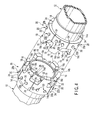
- FIGS. 1 and 2 show an entire configuration of the coupling apparatus 10 according to the first embodiment of the present invention.
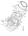
- FIG. 1 is a perspective view schematically showing two of the coupling apparatus 10 according to the first embodiment of the present invention in a state in which the two coupling apparatuses 10 are separated from each other.
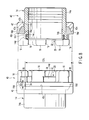
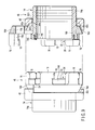
- FIG. 2 is a side view schematically showing the two coupling apparatuses 10 of FIG. 1 with one of the coupling apparatuses being in a cross section.
- the coupling apparatus 10 is used for detachably connecting objects (hereinafter referred to as "objects to be connected") 12 each other.
- objects to be connected is a known flexible hose in which fluid such as water is flown.
- the coupling apparatus 10 includes an annular coupling body 14 which has a proximal end part 14a attached to a predetermined part (one end part, in this embodiment) of the object 12 to be connected and a distal end part 14b located opposite to the proximal end part 14a.
- the coupling apparatus 10 further includes a plurality of fitting projections 16 projecting from a plurality of predetermined circumferential positions on the distal end part 14b of the coupling body 14 along an axial direction of the coupling body 14, and each fitting projection 16 has an engaging hook 18 projecting from its projecting end part in one predetermined circumferential direction.
- the coupling body 14 and the plural fitting projections 16 are formed by a coupling-body formation process and a fitting-projection formation process that are independent of each other.
- the fitting projections 16 are detachably fixed to predetermined circumferential positions on the distal end part 14b of the coupling body 14 by fixing structures 20 which are formed by a fixing-structure formation process and which are independent of the coupling body 14 and fitting projections 16.
- the coupling body 14 has outer dimensions much larger than those of each fitting projection 16 the shape of which is complex. However, the shape of the coupling body 14 is simpler than that of the fitting projection 16. Since the simpler shaped coupling body 14 is formed by the coupling-body formation process independent of the fitting-projection formation process for forming the complex shaped fitting projection 16, a formation cost for the coupling body 14 is low.
- the coupling body 14 has a cylindrical shape, and an elastic member 22 is provided on an end surface of the distal end part 14b.
- the elastic member 22 is an annular rubber sealing member embedded in an embedding groove 14c formed annularly in the end surface of the distal end part 14b, and projects from the end surface by a predetermined amount.
- An outward overhang 14d is provided on a position of the outer periphery of the distal end part 14a of the coupling body 14, the position being adjacent to the end surface of the distal end part 14b, to project outward in the radial direction of the coupling body 14 by a predetermined amount.
- the outward overhang 14d is formed integrally with the coupling body 14.
- the outward overhang 14d may be formed separately from the coupling body 14 and then may be fixed to the predetermined position on the outer periphery of the coupling body 14 by a known fixing structure including for example welding, a fixing screw, or adhesive.
- outward overhang 14d may extend all the way on the outer periphery of the distal end part 14b of the coupling body 14 in its circumferential direction.
- the outward overhang 14d may be disposed on each of plural circumferentially separated positions on the outer periphery of the distal end part 14b of the coupling body 14 to correspond to each of the plural fitting projections 16.
- the plural fitting projections 16 are formed in a plurality of blocks each having a predetermined number of fitting projections 16.
- each block includes two fitting projections 16.
- each block may be formed to include one, three, or more fitting projections 16.
- the fitting projection 16 which is far smaller in outer dimensions than each coupling body 14 but has a shape more complex than that of the coupling body 14, is formed by the fitting-projection formation process independent of the coupling-body formation process for the coupling body 14, the fitting projection 16 can be formed by an inexpensive formation process such as a lost-wax process, a forging process, and the like.
- Each of the plural fitting projections 16 has an inner periphery 16a which is placed on a part of the outer periphery of the distal end part 14b of the coupling body 14, the part being adjacent to the outward overhang 14d in a side thereof opposite to the end surface of the distal end part 14b.
- each fitting projection 16 further has a stepped inner periphery 16c which is in contact with an outer periphery of the outward overhang 14b and a stepped surface between this outer periphery and the above described fitting projection placing part of the outer periphery of the distal end part 14b of the coupling body 14 when the inner periphery 16a is placed on the fitting projection placing part of the outer periphery of the distal end part14b of the coupling body 14.
- the fixing structure 20 includes an insert connection member 20b which is inserted in a through hole 20a formed in at least one of the coupling body 14 and the block including the predetermined number of fitting projections 16 and which is detachably connected to the other.
- the through holes 20a are formed in the block including the predetermined number of fitting projections 16, and the insert connection member 20b is a bolt with a head.
- the insert connection member 20b may be a stud bolt or a stud pin planted in the fitting-projection placing part of the outer periphery of the distal end part 14b of the coupling body 14. And, a nut is screwed on the projecting end part of the stud bolt and a securing pin is combined with the projecting end part of the stud pin.
- a spot facing may be formed around the through hole 20a in the outer surface of the block to receive the head of the headed bolt, the nut screwed on the projecting end part of the stud bolt, or the securing pin combined with the projecting end part of the stud pin serving as the insert connection member 20b, and to prevent these from projecting out from the outer surface.
- Such a spot facing prevent the head of the headed bolt, the nut screwed on the projecting end part of the stud bolt, or the securing pin combined with the projecting end part of the stud pin serving as the insert connection member 20b, from striking an outer object and being damaged by the strike.
- the spot facing prevent the block, that is the fitting projections 16, from being displaced or separated from the predetermined position on the outer periphery of the distal end part 14b of the coupling body 14.
- the pressure deformable member 24 may be an elastic member including for example rubber, or a metal of relatively low hardness.
- the pressure deformable members 24 prevent the plural fitting projections 16 fixed on the plural predetermined positions of the outer periphery of the distal end part 14b of the coupling body 14 by the fixing structures 20 as described above, from being displaced in the circumferential direction.
- the two coupling apparatuses 10, 10 configured as described above with reference to FIGS. 1 and 2 will be detachably connected in the following manner.
- the two coupling apparatuses 10 approach coaxially to each other until the fitting projections 16 of one of the two coupling apparatus 10 fit in fitting recesses between the fitting projections 16 of the other coupling apparatus 10.
- the coupling body 14 of the one coupling apparatus 10 is rotated in a predetermined circumferential direction relative to the coupling body 14 of the other coupling apparatus 10.
- the engaging hooks 18 of the fitting projections 16 of the one coupling apparatus 10 engage with the engaging hooks 18 of the fitting projections 16 of the other coupling apparatus 10, as shown in FIG. 3 , and thus the two coupling apparatuses 10, 10 are detachably connected to each other.
- the elastic members 22 configure a friction increasing mechanism 26 which presses the coupling bodies 14 of the two coupling apparatuses 10 to move the coupling bodies 14 away from each other in the axial direction when the two coupling apparatuses 10, 10 are coupled each other, thus increasing the friction force loaded on the engaging hooks 18 of the fitting projections 16 of the coupling apparatuses 10, 10.
- the locking surface 18a inclines from its proximal end at which the engaging hook 18 projects from the fitting projection 16 corresponding thereto toward its distal end such that its distal end approaches the proximal end of the fitting projection 16 corresponding thereto. This inclination makes the above described engagement of the locking surface 18a of the engaging hook 18 of each fitting projection 16 of the one coupling apparatus 10 with that of the other coupling apparatus 10 strengthen.
- the objects 12 to be connected to which the coupling apparatuses 10 are attached are known flexible hoses for flowing fluid such as water, as described above.
- the elastic bodies 22 on the end surfaces of the distal end parts 14b of the coupling bodies 14 of the two coupling apparatuses 10 expand outward in the radial direction of each coupling body 14 by the pressure of the fluid.
- the expanded elastic bodies 22 urges the coupling bodies 14 of the two coupling apparatuses 10 to make the coupling bodies 14 move further away from each other in their axial direction.
- the objects 12 to which the coupling apparatuses 10 are attached are known flexible hoses for flowing fluids such as water.
- the objects 12 to be connected may be hard pipes or solid bodies.
- the coupling apparatuses 10 facilitate the assembly and disassembly of such a structure.
- the block having a predetermined number of fitting projections 16 may be fixed to each of plural coupling bodies 14 of different diameters by the fixing structure 20.
- the coupling apparatus 10 of the configuration according to the above described embodiment can reduce the manufacturing costs of various coupling apparatuses 10 having the coupling bodies 14 of various diameters, compared to the conventional one. Further, even when a part of fitting projections 16 or engaging hooks 18 of each coupling apparatus 10 is damaged, it is enough to replace only the block having the damaged part with a new block, so that there is no need to replace the entire damaged coupling apparatus 10 with a new coupling apparatus 10.
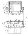
- FIGS. 4 and 5 show the entire configuration of the coupling apparatus 30 according to the second embodiment of the present invention.
- FIG. 4 is a perspective view schematically showing two of the coupling apparatus 30 according to the second embodiment of the present invention in a state in which the two coupling apparatuses 30 are separated from each other
- FIG. 5 is a side view of the two coupling apparatuses 30 of FIG. 4 with one of the two coupling apparatuses 30 being cross sectioned.
- the component members of the coupling apparatus 30 according to the second embodiment is the same as that of the coupling apparatus 10 according to the first embodiment described above with reference to FIGS. 1 to 3 . Accordingly, in the coupling apparatus 30 according to the second embodiment of the present invention and described below with reference to FIGS. 4 to 6 , the component members corresponding to those in the coupling apparatus 10 according to the first embodiment of the present invention and described above with reference to FIGS. 1 to 3 are indicated by the same reference numbers as those indicating the corresponding ones in the coupling apparatus 10 according to the first embodiment of the present invention and described above with reference to FIGS. 1 to 3 , and detailed explanations thereof are omitted.
- the difference in structure of the coupling apparatus 30 according to the second embodiment from the coupling apparatus 10 according to the first embodiment is as follows.
- each block may have more than one fitting projection 16.
- the urging mechanisms 32 move the side surfaces 16d of the fitting projections 16 of one coupling apparatus 30 away from the side surfaces 16d of the fitting projections 16 of the other coupling apparatus 30, the former side surface facing the latter side surface.
- the fitting projections 16 of the one coupling apparatus 30 are urged relative to the fitting projections 16 of the other coupling apparatus 30 in such a predetermined circumferential direction that the engagement of the engaging hooks 18 of the fitting projections 16 of the one coupling apparatus 30 with those of the other coupling apparatus 30 is more strengthened.
- the two side surfaces located in the circumferential direction of the coupling body 14 and extending in the direction along the axial direction of this coupling body 14 extend in parallel to and in the same direction relative to the axial direction.
- the two side surfaces are also located in the circumferential direction of the coupling body 14 and extend in the direction along the axial direction of this coupling body 14, but one of the two side surfaces from which the engaging hook 18 projects at its projecting end part extends in the direction along the axial direction of this coupling body 14 and the other side surface 16c located opposite to the one side surface inclines to being away from the one side surface while it extends from the projecting end surface of the fitting projection 16 corresponding thereto toward the base end thereof.
- the urging mechanism 32 provided on the other side surface 16c that inclines as described above includes a cup-shaped receptacle 32a embedded in a predetermined position of the other side surface 16c.
- the urging mechanism 32 further includes a ball-shaped pressing member 32b disposed at a position close to the other side surface 16c in the cup-shaped receptacle 32a, and an urging member 32c disposed at a position away from the other side surface 16c in the cup-shaped receptacle 32a.
- the urging member 32c urges the ball-shaped pressing member 32b in a direction in which the ball-shaped pressing member 32b projects from the other side surface 16c.
- the portion close to the other side surface 16c in the cup-shaped receptacle 32a is worked to have a diameter smaller than that of the ball-shaped pressing member 32b.
- the pressing member 32c is a compression coil spring, but it may be an elastic member such as a rubber member.
- the urging mechanism 32 acts in a manner as described below.
- the ball-shaped pressing member 32b of the urging mechanism 32 of the other side surface 16c of each fitting projection 16 of the one coupling apparatus 30 and the ball-shaped pressing member 32b of the urging mechanism 32 of the other side surface 16c of each fitting projection 16 of the other coupling apparatus 30 come into contact with each other so that each ball-shaped pressing member 32b moves inward in the respective cup-shaped receptacle 32a against the urging force of the urging member 32c corresponding thereto.
- the elastic members 22 on the end surfaces of the distal end parts 14b of the coupling bodies 14 of the two coupling apparatuses 30, 30 are pressed against each other to urge the coupling bodies 14 of the two coupling apparatuses 30, 30 away from each other in their axial direction, and thus the friction force generated between the locking surface 18a of the engaging hook 18 of each fitting projection 16 of the one coupling apparatus 30 and the locking surface 18a of the engaging hook 18 of each fitting projection 16 of the other coupling apparatus 30 is increased.
- the urging force of the urging member 32c of the urging mechanism 32 of the other side surface 16d of each fitting projection 16 of the one coupling apparatus 30 and the urging force of the urging member 32c of the urging mechanism 32 of the other side surface 16d of each fitting projection 16 of the other coupling apparatus 30 further increase the friction force generated between the engaging surface 18a of the engaging hook 18 of each fitting projection 16 of the one coupling apparatus 30 and the engaging surface 18a of the engaging hook 18 of each fitting projection 16 of the other coupling apparatus 30, through the ball-shaped pressing members 32 being kept in contact with each other as described above.
- the coupling apparatus 30 according to the second embodiment described above with reference to FIGS. 4 to 6 can enjoy the various actions and technical advantages obtained by the coupling apparatus 10 according to the first embodiment described above with reference to FIGS. 1 to 3 .
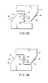
- FIG. 13A shows a fitting projection 16' according to a first modification of the fitting projection 16 used in each of the coupling apparatuses described above.
- the fitting projection 16' is formed with a key-shaped part preventing the engaging hooks 18 of the fitting projections 16' of the one coupling apparatus from engaging with the engaging hooks 18 of the fitting projections 16' of the other coupling apparatus when the two coupling apparatuses are coaxially approached each other and the fitting projections 16' of the one coupling apparatus fit the fitting recesses between the fitting projections 16' of the other coupling apparatus and then the coupling body 14 of the one coupling apparatus is rotated relative to the coupling body 14 of the other coupling apparatus in the predetermined circumferential direction, excluding in a case in which the two coupling apparatuses have the same shape with the same dimensions as to each other.
- the key-shaped part 16e is configured by a combination of a projection and a groove both of which are formed at predetermined positions on both sides of the engaging hook 18 in the projecting direction of the fitting projection 16' on the circumferential side surface of the fitting projection 16', on which the engaging hook 18 is formed.
- the groove is formed in the predetermined position outside of the engaging hook 18 in the projecting direction
- the projection is formed in the predetermined position inside of the engaging hook 18 in the projecting direction.
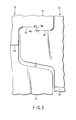
- the engaging hook 18 of the fitting projection 16' of the first modification and the engaging hook 18 of the fitting projection 16 not formed with the key-shaped part 16e only face each other and are prevented from engaging with each other by the key-shaped part 16e of the fitting projection 16', as shown in FIG. 13B .
- the key-shaped parts 16e of the two fitting projections 16' are matched with each other so that the engaging hook 18 of the fitting projection 16' of the first modification and the engaging hook 18 of the fitting projection 16' of the other first modification are allowed to engage with each other.
- FIG. 15A shows a fitting projection 16" according to a second modification of the fitting projection 16 used in each of the coupling apparatuses described above.
- the fitting projection 16" according to the second modification further includes a friction increasing mechanism 60 which presses the coupling bodies 14 of the two coupling apparatuses to move them away from each other in the axial direction when the two coupling apparatuses are coupled with each other, so that the friction force generated between the engaging hooks 18 of the fitting projections 16 of the one coupling apparatus and the engaging hooks 18 of the fitting projections 16 of the other coupling apparatus increases.
- the friction increasing mechanism 60 includes a pressing member 60b which is accommodated in a hole 60a extending from the end surface of the fitting projection 16" toward its base end, and which is slidable in the longitudinal direction of the hole 60a.
- a guide groove 60c formed in the outer periphery of the fitting projection 16" communicates with the hole 60a.
- the guide groove 60c has a longitudinally extending part extending along the longitudinal direction of the hole 60a, and a bend part bending sideway relative to the longitudinal direction of the hole 60a at a projecting-end-surface near end located near to the projecting end surface of the fitting projection 16" in the longitudinally extending part.
- An operating part 60d fixed to the pressing member 60b is inserted in the guide groove 60c.
- the operating part 60d is movable between a projecting-end-surface distal end which is located away from the projecting end surface of the fitting projection 16" in the longitudinally extending part of the guide groove 60c, and the bend part which is located near to the projecting-end-surface near end.
- the pressing member 60b is retracted in the hole 60a and does not project out from the projecting end surface of the fitting projection 16", as shown in FIG. 15A .
- the pressing member 60b projects out from the projecting end surface of the fitting projection 16" by a predetermined distance, as shown in FIG. 15B .
- the two coupling apparatuses can be coupled with or separated from each other.
- the coupling bodies 14 of the two coupling apparatuses coupled with each other are pressed to move away from each other in the axial direction, so that friction force generated between the engaging hooks 18 of the fitting projections 16 of the one coupling apparatus and the engaging hooks 18 of the fitting projections 16 of the other coupling apparatus.
- each of the two coupling apparatuses to be connected may have at least one fitting projection 16".
- FIGS. 16A and 16B show a fitting projection 16"' according to a third modification of the fitting projection 16 used in each of the coupling apparatuses described above.
- a handle 70 is fixed to an outer periphery of the fitting projection 16"' according to the third modification.
- the handle 70 facilitates the attachment and detachment of the fitting projection 16"' according to the third modification to the coupling body 14 of the coupling apparatus 20, 30, 40, or 50 corresponding thereto.
- the handle 70 may be detachably fixed to the outer periphery of the fitting projection 16"' according to the third modification by a known detachable fixing structure such as screwing or the like.
- the handle 70 is fixed to the outer periphery of the fixing projection 16"' according to the third modification, thereby facilitating the attachment and detachment of the fitting projection 16"'. Then, after the fitting projection 16"' according to the third modification is fixed to the coupling body 14 of the coupling apparatus 20, 30, 40, or 50 corresponding thereto by the fixing structure 20 or 42, the handle 70 is removed from the outer periphery of the fitting projection 16"' according to the third modification, so that the handle 70 does not make the handling of the coupling apparatus 20, 30, 40, or 50 being troublesome.
- the coupling apparatuses are used to detachably connect objects such as pipes, solid objects, hoses, and the like to each other.
Landscapes
- Engineering & Computer Science (AREA)
- General Engineering & Computer Science (AREA)
- Mechanical Engineering (AREA)
- Quick-Acting Or Multi-Walled Pipe Joints (AREA)
- Mutual Connection Of Rods And Tubes (AREA)
Claims (9)
- Kupplungsvorrichtung (10, 30), die einen ringförmigen Kupplungskörper (14) umfasst, der ein proximales Endteil (14a), das an einem vorgegebenen Teil eines zu verbindenden Objekts (12) befestigt ist, und ein distales Endteil (14b), das dem proximalen Endteil gegenüberliegend positioniert ist, aufweist; und
mehrere Passvorsprünge (16), die entlang einer axialen Richtung des Kupplungskörpers von mehreren vorgegebenen Umfangspositionen an dem distalen Endteil des Kupplungskörpers vorstehen, wobei jeder Passvorsprung einen Eingriffshaken (18) aufweist, der in einer vorgegebenen Umfangsrichtung an einem vorstehenden Endteil davon vorsteht, wobei sich zwei der Kupplungsvorrichtungen koaxial annähern, um die Passvorsprünge einer Kupplungsvorrichtung in Passaussparungen zwischen den Passvorsprüngen der anderen Kupplungsvorrichtung einzupassen, wobei der Kupplungskörper der einen Kupplungsvorrichtung nachfolgend in einer vorgegebenen Umfangsrichtung relativ zu dem Kupplungskörper der anderen Kupplungsvorrichtung gedreht wird, um zu veranlassen, dass die Eingriffshaken der Passvorsprünge der einen Kupplungsvorrichtung mit den Eingriffshaken der Passvorsprünge der anderen Kupplungsvorrichtung in Eingriff gelangen, und um somit die zwei Kupplungsvorrichtungen lösbar miteinander zu verbinden,
wobei der Kupplungskörper (14) und die mehreren Passvorsprünge (16) unabhängig voneinander gebildet sind, und
dadurch gekennzeichnet, dass die Kupplungsvorrichtung ferner eine Befestigungsstruktur (20) umfasst, die unabhängig von dem Kupplungskörper und von den Passvorsprüngen ist und die Passvorsprünge an den vorgegebenen Umfangspositionen an dem distalen Endteil (14b) des Kupplungskörpers lösbar befestigt, wobei die Befestigungsstruktur (20) ein Einsatzverbindungselement (20b) enthält, das in ein in wenigstens einem des Kupplungskörpers (14) und des Passvorsprungs (16) gebildetes Durchgangsloch (20a) eingesetzt ist und das lösbar mit dem anderen verbunden ist. - Kupplungsvorrichtung nach Anspruch 1, dadurch gekennzeichnet, dass sie ferner einen Antriebsmechanismus (32) umfasst, der an wenigstens einem der mehreren Passvorsprünge (16) auf einer dem Eingriffshaken (18) gegenüberliegenden Seite angeordnet ist und der eine andere Kupplungsvorrichtung in der vorgegebenen Umfangsrichtung antreibt, wenn die zwei Kupplungsvorrichtungen (30, 30) miteinander gekoppelt werden.
- Kupplungsvorrichtung nach Anspruch 1, dadurch gekennzeichnet, dass sie ferner einen Reibungserhöhungsmechanismus (26, 60) umfasst, der die Kupplungskörper (14) der zwei Kupplungsvorrichtungen antreibt, um zu veranlassen, dass sich die Kupplungskörper (14) entlang der axialen Richtung voneinander fortbewegen, wenn die zwei Kupplungsvorrichtungen (10, 10 oder 30, 30) miteinander gekoppelt sind, und der ferner die zwischen den Eingriffshaken (18) der Passvorsprünge (16) der einen Kupplungsvorrichtung und den Eingriffshaken (18) der Passvorsprünge (16) der anderen Kupplungsvorrichtung erzeugte Reibungskraft erhöht.
- Kupplungsvorrichtung nach Anspruch 3, dadurch gekennzeichnet, dass der Reibungserhöhungsmechanismus (26) ein elastisches Element (22) enthält, das an einer Stirnfläche des distalen Endteils (14b) des Kupplungskörpers (14) angeordnet ist, und wobei, wenn die zwei Kupplungsvorrichtungen (10, 10 oder 30, 30) miteinander gekoppelt sind, die elastischen Elemente (22) an den Stirnflächen der distalen Endteile (14b) der Kupplungskörper (14) der zwei Kupplungsvorrichtungen (10, 10 oder 30, 30) zusammengepresst werden, um die Kupplungskörper (14) der zwei Kupplungsvorrichtungen (10, 10 oder 30, 30) anzutreiben, um zu veranlassen, dass sich die Kupplungskörper (14) entlang der axialen Richtung voneinander fortbewegen, und um die zwischen den Eingriffshaken (18) der Passvorsprünge (16) der einen Kupplungsvorrichtung und den Eingriffshaken (18) der Passvorsprünge (16) der anderen Kupplungsvorrichtung erzeugte Reibungskraft zu erhöhen.
- Kupplungsvorrichtung nach Anspruch 1, dadurch gekennzeichnet, dass wenigstens eines der mit den Kupplungskörpern (14) der zwei Kupplungsvorrichtungen (10, 10 oder 30, 30) verbundenen Objekte (12) ein biegsamer Schlauch zum Strömen eines Fluids ist.
- Kupplungsvorrichtung nach Anspruch 1, dadurch gekennzeichnet, dass wenigstens eines der mit den Kupplungskörpern (14) der zwei Kupplungsvorrichtungen (10, 10 oder 30, 30) verbundenen Objekte (12) ein Rohr oder ein Vollelement ist.
- Kupplungsvorrichtung nach Anspruch 1, dadurch gekennzeichnet, dass an wenigstens einem der mehreren Passvorsprünge (16) ein Betätigungsgriff (70) vorgesehen ist.
- Kupplungsvorrichtung nach Anspruch 1, dadurch gekennzeichnet, dass die mehreren Passvorsprünge (16) in mehreren Blöcken gebildet sind, wobei jeder die vorgegebene Anzahl von Passvorsprüngen aufweist.
- Kupplungsvorrichtung nach einem der Ansprüche 1 bis 8, dadurch gekennzeichnet, dass an wenigstens einem der Passvorsprünge (16) ein passfederförmiges Teil (16e) gebildet ist, wobei das passfederförmige Teil verhindert, dass die Eingriffshaken (18) der Passvorsprünge (16) der einen Kupplungsvorrichtung mit den Eingriffshaken (18) der Passvorsprünge (16) der anderen Kupplungsvorrichtung in Eingriff gelangen, wenn die zwei Kupplungsvorrichtungen (10, 10 oder 30, 30) einander koaxial angenähert werden, und wobei ausschließlich in einem Fall, in dem die zwei Kupplungsvorrichtungen dieselbe Form mit denselben Dimensionen aufweisen, die Passvorsprünge (16) der einen Kupplungsvorrichtung in die Passaussparungen zwischen den Passvorsprüngen (16) der anderen Kupplungsvorrichtung eingepasst werden und daraufhin der Kupplungskörper (14) der einen Kupplungsvorrichtung relativ zu dem Kupplungskörper (14) der anderen Kupplungsvorrichtung in der vorgegebenen Umfangsichtung gedreht wird.
Priority Applications (1)
| Application Number | Priority Date | Filing Date | Title |
|---|---|---|---|
| EP14181122.4A EP2806201B1 (de) | 2006-10-11 | 2006-10-11 | Kupplungsvorrichtung |
Applications Claiming Priority (1)
| Application Number | Priority Date | Filing Date | Title |
|---|---|---|---|
| PCT/JP2006/320335 WO2008044296A1 (en) | 2006-10-11 | 2006-10-11 | Coupling device |
Related Child Applications (2)
| Application Number | Title | Priority Date | Filing Date |
|---|---|---|---|
| EP14181122.4A Division EP2806201B1 (de) | 2006-10-11 | 2006-10-11 | Kupplungsvorrichtung |
| EP14181122.4A Division-Into EP2806201B1 (de) | 2006-10-11 | 2006-10-11 | Kupplungsvorrichtung |
Publications (3)
| Publication Number | Publication Date |
|---|---|
| EP2075497A1 EP2075497A1 (de) | 2009-07-01 |
| EP2075497A4 EP2075497A4 (de) | 2014-04-16 |
| EP2075497B1 true EP2075497B1 (de) | 2015-09-02 |
Family
ID=39282507
Family Applications (2)
| Application Number | Title | Priority Date | Filing Date |
|---|---|---|---|
| EP06811642.5A Active EP2075497B1 (de) | 2006-10-11 | 2006-10-11 | Verbindungsvorrichtung |
| EP14181122.4A Active EP2806201B1 (de) | 2006-10-11 | 2006-10-11 | Kupplungsvorrichtung |
Family Applications After (1)
| Application Number | Title | Priority Date | Filing Date |
|---|---|---|---|
| EP14181122.4A Active EP2806201B1 (de) | 2006-10-11 | 2006-10-11 | Kupplungsvorrichtung |
Country Status (5)
| Country | Link |
|---|---|
| US (1) | US7798537B2 (de) |
| EP (2) | EP2075497B1 (de) |
| JP (1) | JPWO2008044296A1 (de) |
| CA (1) | CA2664551C (de) |
| WO (1) | WO2008044296A1 (de) |
Families Citing this family (16)
| Publication number | Priority date | Publication date | Assignee | Title |
|---|---|---|---|---|
| GB0912484D0 (en) * | 2009-07-20 | 2009-08-26 | Rolls Royce Plc | Mechanical joint |
| JP4633856B1 (ja) * | 2010-04-02 | 2011-02-16 | 紀文 伊島 | レセプタクルコネクタ |
| US8328244B2 (en) * | 2010-07-13 | 2012-12-11 | Robin Boley-Johnson, legal representative | Split GXR collar front mounted clamp assembly |
| US9370898B2 (en) | 2010-11-11 | 2016-06-21 | Joinlock Pty Ltd. | Connecting method |
| JP5918001B2 (ja) * | 2012-04-26 | 2016-05-18 | 株式会社エム・アイ・ティ | 煙突の接続装置 |
| US9976393B2 (en) * | 2013-10-04 | 2018-05-22 | Cameron International Corporation | Connector, diverter, and annular blowout preventer for use within a mineral extraction system |
| GB201400282D0 (en) * | 2014-01-08 | 2014-02-26 | Connext Ltd | Pipe Fitting |
| EP3176485B1 (de) | 2014-07-29 | 2018-12-19 | Sakura Rubber Co., Ltd. | Kopplungsbeschlag mit sicherheitsventilfunktion |
| DE102014119501B4 (de) | 2014-12-23 | 2018-08-23 | Winfried Felber | Vorrichtung zum Verbinden zweier rohrförmiger Rohrelemente gleichen oder ungleichen Außendurchmessers |
| DE202018001710U1 (de) * | 2018-04-03 | 2018-06-12 | Hytrans Beheer B.V. | Kupplungsteil und damit ausgestattete Schlauchkupplung, ausgelegt für die Kupplung eines Schlauchs oder Schlauchteils |
| CN110469740A (zh) * | 2019-08-30 | 2019-11-19 | 佛山联博工程科技有限公司 | 星型自锁接口 |
| US11460137B2 (en) * | 2020-03-12 | 2022-10-04 | Parker-Hannifin Corporation | Fluid connection systems |
| JP7030925B1 (ja) * | 2020-10-09 | 2022-03-07 | 櫻護謨株式会社 | 結合構造 |
| CN112252825B (zh) * | 2020-10-23 | 2022-03-29 | 宿迁学院 | 一种便于安装的装配式围墙及其施工方法 |
| JP7452868B2 (ja) * | 2021-03-01 | 2024-03-19 | 株式会社山田製作所 | 連結具 |
| JP2024095445A (ja) * | 2022-12-28 | 2024-07-10 | ニデック株式会社 | 接続部材および接続ユニット |
Family Cites Families (20)
| Publication number | Priority date | Publication date | Assignee | Title |
|---|---|---|---|---|
| US545066A (en) * | 1895-08-27 | Hose-coupling | ||
| US658863A (en) * | 1900-01-17 | 1900-10-02 | Frank Pfeffer | Pipe fitting or coupling. |
| US966925A (en) * | 1909-01-26 | 1910-08-09 | Henry E Kittredge | Hose-coupling. |
| US1044183A (en) * | 1911-04-05 | 1912-11-12 | Harmon L Irwin | Hose and pipe coupling. |
| US1794905A (en) * | 1925-10-01 | 1931-03-03 | Samuel M Kass | Pipe joint |
| US2087180A (en) * | 1936-05-20 | 1937-07-13 | Vernon C Smith | Hose coupling |
| US2142452A (en) * | 1937-04-07 | 1939-01-03 | M B Skinner Company | Pipe joint seal |
| CH219993A (de) * | 1941-05-01 | 1942-03-15 | Sifrag Siebenmann & Frei A G | Rohrverbindung. |
| US4097069A (en) * | 1976-04-08 | 1978-06-27 | Mcevoy Oilfield Equipment Company | Marine riser connector |
| AU512414B2 (en) * | 1977-01-27 | 1980-10-09 | Heer, Heinrich Snr. | Non-sliding spigot and socket joint |
| JPS5821088A (ja) * | 1981-07-31 | 1983-02-07 | 住友金属鉱山株式会社 | ジヨイント構造 |
| JP3107507B2 (ja) * | 1995-10-24 | 2000-11-13 | 櫻護謨株式会社 | ホースの結合金具 |
| AU4573397A (en) * | 1997-10-16 | 1999-05-10 | Sakura Rubber Co., Ltd. | Joint and method of manufacturing the same |
| JP4469473B2 (ja) * | 2000-07-26 | 2010-05-26 | 櫻護謨株式会社 | 接続装置 |
| JP4601780B2 (ja) * | 2000-07-26 | 2010-12-22 | 櫻護謨株式会社 | ホースの結合金具 |
| JP2002327881A (ja) * | 2001-04-27 | 2002-11-15 | Okamoto Kensetsu Yohin Seisakusho:Kk | 流体配管用継手 |
| JP4713034B2 (ja) * | 2001-09-28 | 2011-06-29 | 櫻護謨株式会社 | 結合金具 |
| ATE458958T1 (de) * | 2002-03-05 | 2010-03-15 | Sakura Rubber | Kupplungsvorrichtung mit lösungsverhinderungskonstruktion |
| JP4620337B2 (ja) * | 2003-09-05 | 2011-01-26 | 櫻護謨株式会社 | 解除防止構造を備えた結合装置 |
| FR2866942B1 (fr) * | 2004-03-01 | 2006-04-14 | Inst Francais Du Petrole | Connecteur pour colonne montante haute pression |
-
2006
- 2006-10-11 EP EP06811642.5A patent/EP2075497B1/de active Active
- 2006-10-11 EP EP14181122.4A patent/EP2806201B1/de active Active
- 2006-10-11 WO PCT/JP2006/320335 patent/WO2008044296A1/ja not_active Ceased
- 2006-10-11 CA CA2664551A patent/CA2664551C/en active Active
- 2006-10-11 JP JP2008538534A patent/JPWO2008044296A1/ja active Pending
-
2009
- 2009-03-26 US US12/411,682 patent/US7798537B2/en active Active
Also Published As
| Publication number | Publication date |
|---|---|
| EP2075497A1 (de) | 2009-07-01 |
| US20090184518A1 (en) | 2009-07-23 |
| JPWO2008044296A1 (ja) | 2010-02-04 |
| US7798537B2 (en) | 2010-09-21 |
| CA2664551A1 (en) | 2008-04-17 |
| EP2806201A1 (de) | 2014-11-26 |
| EP2806201B1 (de) | 2016-08-03 |
| CA2664551C (en) | 2013-11-26 |
| WO2008044296A1 (en) | 2008-04-17 |
| EP2075497A4 (de) | 2014-04-16 |
Similar Documents
| Publication | Publication Date | Title |
|---|---|---|
| US7798537B2 (en) | Coupling apparatus | |
| US6186561B1 (en) | Retainer for piping connector | |
| US6450545B1 (en) | Fluid coupling plug | |
| CN105333249B (zh) | 具有径向负荷的卡套夹头 | |
| EP1484545B1 (de) | Kupplungsvorrichtung mit lösungsverhinderungskonstruktion | |
| EP1235023B1 (de) | Kupplungsvorrichtung | |
| CN101463851B (zh) | 伸缩式连接杆 | |
| CN105992883B (zh) | 等速接头 | |
| KR20140008346A (ko) | 관 조인트 | |
| EP0616165A1 (de) | Rohrkupplung | |
| CN115076488A (zh) | 一种自锁式快速接头 | |
| CA2199882A1 (en) | Barbed tubular connectors | |
| WO2005073613A1 (en) | Connector with release mechanism | |
| JP4542364B2 (ja) | 管接続構造及び挿口管部への管内作業機の取付け方法 | |
| KR102601458B1 (ko) | 파이프 연결용 소켓 조인트 | |
| EP1359365A2 (de) | Rohrverbindung | |
| KR100324547B1 (ko) | 퀵타입 커플링 | |
| JP2009545715A (ja) | 雌のねじ付カップリングとの接続用の雄のカップリング | |
| JP4200495B2 (ja) | 折畳杖 | |
| WO2011001376A1 (en) | Pipe coupling | |
| JP2003090479A (ja) | 配管類の結合金具 | |
| JPH0315907Y2 (de) | ||
| JP2006292105A (ja) | 継手装置 | |
| JP2005061469A (ja) | 管継手 | |
| JP2017129196A (ja) | 管部の接続構造 |
Legal Events
| Date | Code | Title | Description |
|---|---|---|---|
| PUAI | Public reference made under article 153(3) epc to a published international application that has entered the european phase |
Free format text: ORIGINAL CODE: 0009012 |
|
| 17P | Request for examination filed |
Effective date: 20090511 |
|
| AK | Designated contracting states |
Kind code of ref document: A1 Designated state(s): AT BE BG CH CY CZ DE DK EE ES FI FR GB GR HU IE IS IT LI LT LU LV MC NL PL PT RO SE SI SK TR |
|
| AX | Request for extension of the european patent |
Extension state: AL BA HR MK RS |
|
| DAX | Request for extension of the european patent (deleted) | ||
| A4 | Supplementary search report drawn up and despatched |
Effective date: 20140314 |
|
| RIC1 | Information provided on ipc code assigned before grant |
Ipc: F16L 37/252 20060101ALI20140310BHEP Ipc: F16L 37/24 20060101AFI20140310BHEP Ipc: F16L 37/113 20060101ALI20140310BHEP |
|
| GRAP | Despatch of communication of intention to grant a patent |
Free format text: ORIGINAL CODE: EPIDOSNIGR1 |
|
| INTG | Intention to grant announced |
Effective date: 20150409 |
|
| GRAS | Grant fee paid |
Free format text: ORIGINAL CODE: EPIDOSNIGR3 |
|
| GRAA | (expected) grant |
Free format text: ORIGINAL CODE: 0009210 |
|
| AK | Designated contracting states |
Kind code of ref document: B1 Designated state(s): AT BE BG CH CY CZ DE DK EE ES FI FR GB GR HU IE IS IT LI LT LU LV MC NL PL PT RO SE SI SK TR |
|
| REG | Reference to a national code |
Ref country code: GB Ref legal event code: FG4D |
|
| REG | Reference to a national code |
Ref country code: AT Ref legal event code: REF Ref document number: 746830 Country of ref document: AT Kind code of ref document: T Effective date: 20150915 Ref country code: CH Ref legal event code: EP |
|
| REG | Reference to a national code |
Ref country code: IE Ref legal event code: FG4D |
|
| REG | Reference to a national code |
Ref country code: DE Ref legal event code: R096 Ref document number: 602006046527 Country of ref document: DE |
|
| REG | Reference to a national code |
Ref country code: AT Ref legal event code: MK05 Ref document number: 746830 Country of ref document: AT Kind code of ref document: T Effective date: 20150902 |
|
| PG25 | Lapsed in a contracting state [announced via postgrant information from national office to epo] |
Ref country code: LV Free format text: LAPSE BECAUSE OF FAILURE TO SUBMIT A TRANSLATION OF THE DESCRIPTION OR TO PAY THE FEE WITHIN THE PRESCRIBED TIME-LIMIT Effective date: 20150902 Ref country code: GR Free format text: LAPSE BECAUSE OF FAILURE TO SUBMIT A TRANSLATION OF THE DESCRIPTION OR TO PAY THE FEE WITHIN THE PRESCRIBED TIME-LIMIT Effective date: 20151203 Ref country code: FI Free format text: LAPSE BECAUSE OF FAILURE TO SUBMIT A TRANSLATION OF THE DESCRIPTION OR TO PAY THE FEE WITHIN THE PRESCRIBED TIME-LIMIT Effective date: 20150902 Ref country code: LT Free format text: LAPSE BECAUSE OF FAILURE TO SUBMIT A TRANSLATION OF THE DESCRIPTION OR TO PAY THE FEE WITHIN THE PRESCRIBED TIME-LIMIT Effective date: 20150902 |
|
| REG | Reference to a national code |
Ref country code: LT Ref legal event code: MG4D Ref country code: NL Ref legal event code: MP Effective date: 20150902 |
|
| PG25 | Lapsed in a contracting state [announced via postgrant information from national office to epo] |
Ref country code: SE Free format text: LAPSE BECAUSE OF FAILURE TO SUBMIT A TRANSLATION OF THE DESCRIPTION OR TO PAY THE FEE WITHIN THE PRESCRIBED TIME-LIMIT Effective date: 20150902 Ref country code: AT Free format text: LAPSE BECAUSE OF FAILURE TO SUBMIT A TRANSLATION OF THE DESCRIPTION OR TO PAY THE FEE WITHIN THE PRESCRIBED TIME-LIMIT Effective date: 20150902 Ref country code: ES Free format text: LAPSE BECAUSE OF FAILURE TO SUBMIT A TRANSLATION OF THE DESCRIPTION OR TO PAY THE FEE WITHIN THE PRESCRIBED TIME-LIMIT Effective date: 20150902 Ref country code: PL Free format text: LAPSE BECAUSE OF FAILURE TO SUBMIT A TRANSLATION OF THE DESCRIPTION OR TO PAY THE FEE WITHIN THE PRESCRIBED TIME-LIMIT Effective date: 20150902 |
|
| PG25 | Lapsed in a contracting state [announced via postgrant information from national office to epo] |
Ref country code: IT Free format text: LAPSE BECAUSE OF FAILURE TO SUBMIT A TRANSLATION OF THE DESCRIPTION OR TO PAY THE FEE WITHIN THE PRESCRIBED TIME-LIMIT Effective date: 20150902 Ref country code: CZ Free format text: LAPSE BECAUSE OF FAILURE TO SUBMIT A TRANSLATION OF THE DESCRIPTION OR TO PAY THE FEE WITHIN THE PRESCRIBED TIME-LIMIT Effective date: 20150902 Ref country code: IS Free format text: LAPSE BECAUSE OF FAILURE TO SUBMIT A TRANSLATION OF THE DESCRIPTION OR TO PAY THE FEE WITHIN THE PRESCRIBED TIME-LIMIT Effective date: 20160102 Ref country code: SK Free format text: LAPSE BECAUSE OF FAILURE TO SUBMIT A TRANSLATION OF THE DESCRIPTION OR TO PAY THE FEE WITHIN THE PRESCRIBED TIME-LIMIT Effective date: 20150902 Ref country code: EE Free format text: LAPSE BECAUSE OF FAILURE TO SUBMIT A TRANSLATION OF THE DESCRIPTION OR TO PAY THE FEE WITHIN THE PRESCRIBED TIME-LIMIT Effective date: 20150902 Ref country code: NL Free format text: LAPSE BECAUSE OF FAILURE TO SUBMIT A TRANSLATION OF THE DESCRIPTION OR TO PAY THE FEE WITHIN THE PRESCRIBED TIME-LIMIT Effective date: 20150902 |
|
| PG25 | Lapsed in a contracting state [announced via postgrant information from national office to epo] |
Ref country code: RO Free format text: LAPSE BECAUSE OF FAILURE TO SUBMIT A TRANSLATION OF THE DESCRIPTION OR TO PAY THE FEE WITHIN THE PRESCRIBED TIME-LIMIT Effective date: 20150902 Ref country code: PT Free format text: LAPSE BECAUSE OF FAILURE TO SUBMIT A TRANSLATION OF THE DESCRIPTION OR TO PAY THE FEE WITHIN THE PRESCRIBED TIME-LIMIT Effective date: 20160104 |
|
| REG | Reference to a national code |
Ref country code: CH Ref legal event code: PL |
|
| REG | Reference to a national code |
Ref country code: DE Ref legal event code: R097 Ref document number: 602006046527 Country of ref document: DE |
|
| PG25 | Lapsed in a contracting state [announced via postgrant information from national office to epo] |
Ref country code: MC Free format text: LAPSE BECAUSE OF FAILURE TO SUBMIT A TRANSLATION OF THE DESCRIPTION OR TO PAY THE FEE WITHIN THE PRESCRIBED TIME-LIMIT Effective date: 20150902 |
|
| PLBE | No opposition filed within time limit |
Free format text: ORIGINAL CODE: 0009261 |
|
| STAA | Information on the status of an ep patent application or granted ep patent |
Free format text: STATUS: NO OPPOSITION FILED WITHIN TIME LIMIT |
|
| REG | Reference to a national code |
Ref country code: IE Ref legal event code: MM4A |
|
| PG25 | Lapsed in a contracting state [announced via postgrant information from national office to epo] |
Ref country code: LI Free format text: LAPSE BECAUSE OF NON-PAYMENT OF DUE FEES Effective date: 20151031 Ref country code: CH Free format text: LAPSE BECAUSE OF NON-PAYMENT OF DUE FEES Effective date: 20151031 |
|
| REG | Reference to a national code |
Ref country code: FR Ref legal event code: ST Effective date: 20160630 |
|
| 26N | No opposition filed |
Effective date: 20160603 |
|
| PG25 | Lapsed in a contracting state [announced via postgrant information from national office to epo] |
Ref country code: FR Free format text: LAPSE BECAUSE OF NON-PAYMENT OF DUE FEES Effective date: 20151102 Ref country code: DK Free format text: LAPSE BECAUSE OF FAILURE TO SUBMIT A TRANSLATION OF THE DESCRIPTION OR TO PAY THE FEE WITHIN THE PRESCRIBED TIME-LIMIT Effective date: 20150902 Ref country code: SI Free format text: LAPSE BECAUSE OF FAILURE TO SUBMIT A TRANSLATION OF THE DESCRIPTION OR TO PAY THE FEE WITHIN THE PRESCRIBED TIME-LIMIT Effective date: 20150902 |
|
| PG25 | Lapsed in a contracting state [announced via postgrant information from national office to epo] |
Ref country code: IE Free format text: LAPSE BECAUSE OF NON-PAYMENT OF DUE FEES Effective date: 20151011 |
|
| PG25 | Lapsed in a contracting state [announced via postgrant information from national office to epo] |
Ref country code: BE Free format text: LAPSE BECAUSE OF FAILURE TO SUBMIT A TRANSLATION OF THE DESCRIPTION OR TO PAY THE FEE WITHIN THE PRESCRIBED TIME-LIMIT Effective date: 20150902 |
|
| PG25 | Lapsed in a contracting state [announced via postgrant information from national office to epo] |
Ref country code: HU Free format text: LAPSE BECAUSE OF FAILURE TO SUBMIT A TRANSLATION OF THE DESCRIPTION OR TO PAY THE FEE WITHIN THE PRESCRIBED TIME-LIMIT; INVALID AB INITIO Effective date: 20061011 Ref country code: BG Free format text: LAPSE BECAUSE OF FAILURE TO SUBMIT A TRANSLATION OF THE DESCRIPTION OR TO PAY THE FEE WITHIN THE PRESCRIBED TIME-LIMIT Effective date: 20150902 |
|
| PG25 | Lapsed in a contracting state [announced via postgrant information from national office to epo] |
Ref country code: CY Free format text: LAPSE BECAUSE OF FAILURE TO SUBMIT A TRANSLATION OF THE DESCRIPTION OR TO PAY THE FEE WITHIN THE PRESCRIBED TIME-LIMIT Effective date: 20150902 |
|
| PG25 | Lapsed in a contracting state [announced via postgrant information from national office to epo] |
Ref country code: TR Free format text: LAPSE BECAUSE OF FAILURE TO SUBMIT A TRANSLATION OF THE DESCRIPTION OR TO PAY THE FEE WITHIN THE PRESCRIBED TIME-LIMIT Effective date: 20150902 |
|
| PG25 | Lapsed in a contracting state [announced via postgrant information from national office to epo] |
Ref country code: LU Free format text: LAPSE BECAUSE OF NON-PAYMENT OF DUE FEES Effective date: 20151011 |
|
| PGFP | Annual fee paid to national office [announced via postgrant information from national office to epo] |
Ref country code: GB Payment date: 20250911 Year of fee payment: 20 |
|
| PGFP | Annual fee paid to national office [announced via postgrant information from national office to epo] |
Ref country code: DE Payment date: 20251029 Year of fee payment: 20 |