EP2075595A2 - Vorrichtung und Verfahren zur Erkennung der Ausrichtung von radioaktivem Material - Google Patents
Vorrichtung und Verfahren zur Erkennung der Ausrichtung von radioaktivem Material Download PDFInfo
- Publication number
- EP2075595A2 EP2075595A2 EP08021549A EP08021549A EP2075595A2 EP 2075595 A2 EP2075595 A2 EP 2075595A2 EP 08021549 A EP08021549 A EP 08021549A EP 08021549 A EP08021549 A EP 08021549A EP 2075595 A2 EP2075595 A2 EP 2075595A2
- Authority
- EP
- European Patent Office
- Prior art keywords
- radioactive material
- radiation detector
- orientation
- detection
- detecting
- Prior art date
- Legal status (The legal status is an assumption and is not a legal conclusion. Google has not performed a legal analysis and makes no representation as to the accuracy of the status listed.)
- Granted
Links
- 239000012857 radioactive material Substances 0.000 title claims abstract description 117
- 238000000034 method Methods 0.000 title claims abstract description 16
- 238000001514 detection method Methods 0.000 claims abstract description 127
- 230000005855 radiation Effects 0.000 claims abstract description 106
- 229920003023 plastic Polymers 0.000 claims description 11
- 239000004033 plastic Substances 0.000 claims description 11
- 239000000463 material Substances 0.000 claims description 9
- 239000004698 Polyethylene Substances 0.000 claims description 6
- -1 polyethylene Polymers 0.000 claims description 6
- 229920000573 polyethylene Polymers 0.000 claims description 6
- 230000000007 visual effect Effects 0.000 description 5
- 230000007547 defect Effects 0.000 description 2
- 238000010586 diagram Methods 0.000 description 2
- 238000009933 burial Methods 0.000 description 1
- 238000007796 conventional method Methods 0.000 description 1
- 230000000694 effects Effects 0.000 description 1
- 230000005251 gamma ray Effects 0.000 description 1
- 230000005658 nuclear physics Effects 0.000 description 1
- 230000002285 radioactive effect Effects 0.000 description 1
- 239000002699 waste material Substances 0.000 description 1
Images


Classifications
-
- G—PHYSICS
- G01—MEASURING; TESTING
- G01T—MEASUREMENT OF NUCLEAR OR X-RADIATION
- G01T7/00—Details of radiation-measuring instruments
-
- G—PHYSICS
- G01—MEASURING; TESTING
- G01T—MEASUREMENT OF NUCLEAR OR X-RADIATION
- G01T3/00—Measuring neutron radiation
Definitions
- the present invention relates to an device and a method for detecting orientation of a radioactive material and, in particular, to a hand-held radiation detection device and a detecting method which not only can detect presence of a radiation source, but also can provide information about orientation of the source, so that position of an unknown radiation source can be quickly determined.
- the hand-held radiation detection device and the detecting method of this invention can be applied to any site where orientation of a radioactive material is required to be detected, such as a customs port, a nuclear physics lab, a nuclear power plant, a burial site or a warehouse for nuclear waste, a hospital, a weapon factory, and so on.
- Conventional portable or hand-held radiation detection device employs a plastic scintillator detector or a 3 He neutron tube detector to detect gamma rays emitted from radioactive material (i.e., a radiation source), and generate an alarm when presence of the radioactive material is detected.
- radioactive material i.e., a radiation source
- a defect of such conventional radiation detection devices is that they only can provide information about radiation intensity where there is radioactive material, but can not determine the position of the radioactive material. Thus, it is very difficult to rapidly determine the orientation of a radioactive material by using the conventional radiation detection device.
- the present invention provides a device for detecting orientation of a radioactive material which not only can detect presence of the radioactive material, but also can detect position of the radioactive material.
- the present invention also provides a method for detecting the position of a radioactive material.
- an device for detecting orientation of a radioactive material comprising at least one first radiation detector; at least one second radiation detector, each of said at least one second radiation detector and each of said at least one first radiation detector being arranged side by side and in pairs, detection surfaces of said first and second radiation detector being in the same plane to receive rays from the same direction in the same manner and to generate a first detection signal and a second detection signal, respectively; a shielding plate arranged between said first radiation detector and said second radiation detector arranged in pairs and extending forward beyond said detection surfaces; and a determination device configured to receive the first and second detection signals from said first and second radiation detector, and determining whether a radioactive material exists or not based on said first and second detection signals and simultaneously determining the orientation of the radioactive material according to the difference between said first detection signal and said second detection signal.
- the device for detecting the orientation of the radioactive material further comprises a first frame and a second frame arranged side by side, said first radiation detector and said second radiation detector being arranged within said first frame and said second frame, respectively.
- a sliding rail mechanism is arranged between said first frame and said second frame, and wherein said shielding plate is slidable within said sliding rail mechanism to allow said shielding plate to extend toward beyond said detection surfaces or retreat backward behind said detection surfaces.
- said shielding plate is provided with a gripping portion.
- said first and second radiation detector are plastic scintillator detectors.
- the portions of said plastic scintillator detectors except the detection surfaces are enclosed by shielding material.
- said first and second radiation detector are 3 He neutron tube detectors.
- the detection surfaces of said 3 He neutron tube detector are provided with a moderating layer made of polyethylene material and having a thickness of about 3cm.
- the portions of said 3 He neutron tube detector except the detection surfaces are provided with a shielding layer made of polyethylene material and having a thickness of about 5-8cm.
- a method for detecting orientation of a radioactive material to determining presence and position of the radioactive material comprising steps of providing a first radiation detector and a second radiation detector side by side and in pairs, and arranging detection surfaces of said first and second radiation detector to be in the same plane so as to receive rays from the same direction in the same manner and to generate first and second detection signals, respectively; providing a shielding plate between said first and second radiation detector arranged in pairs, the shielding plate vertically extending forward beyond said detection surfaces; and determining whether a radioactive material exists or not based on said first and second detection signals, and determining the orientation of the radioactive material according to the difference between the first and second detection signals.
- the device for detecting the orientation of the radioactive material is provided to detect whether a radioactive material exists or not and to determine the position of the radioactive material in a site where the radioactive material (i.e., a radiation source) is suspected to be present.
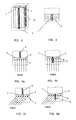
- the orientation detecting device for detecting the orientation of the radioactive material comprises a first radiation detector 1 and a second radiation detector 3 which is identical with the first radiation detector 1 in type and parameter.
- the first and second radiation detector 1 and 3 may be, for example, X-ray detectors or ⁇ -ray detectors.
- a plastic scintillator detector for detecting gamma rays is taken as an example to explain the device for detecting the orientation of the radioactive material according to this invention.
- the first and second radiation detector 1 and 3 are provided side by side and are in a pair.
- Detection surfaces 4 of the first and second radiation detector 1 and 3 are in the same plane to allow the first radiation detector 1 and the second radiation detector 3 to receive gamma rays from the same direction in the same manner and to generate a first detection signal and a second detection signal, respectively.
- Ray receiving operation and electrical-signal generating operation of each of the first radiation detector 1 and the second radiation detector 3 may be same as those of a conventional single radiation detector, such as a plastic scintillator detector and like.
- the generated electrical signal can indicate whether a radiation source exists in the vicinity of the plastic scintillator detector or not and also can indicate the intensity of the detected rays.
- the numbers of the first and second radiation detector may be 1, respectively, i.e., a pair of radiation detectors is provided. Two or three first and second radiation detectors also can be used, i.e., two pairs or three pairs of radiation detectors.
- the first and second detection signals are sums of a reference signal and net detection signals, respectively.
- the reference signal is not zero.
- the device for detecting the orientation of the radioactive material according to this invention further comprises a shielding plate 2, such as a lead plate, for shielding gamma rays.
- the shielding plate 2 is provided between the first radiation detector 1 and the second radiation detector 3 which are in a pair, and vertically extends toward frontage of the detection surfaces 4 (under the detection surfaces in figure 2 ).
- the device for detecting the orientation detecting orientation of the radioactive material according to this invention further comprises a determination device 8 (referring to figure 7 ) to receive the first detection signal and the second detection signal from the first radiation detector 1 and the second radiation detector 3, respectively, and to determine whether the radioactive material exists or not from the first and second detection signals.
- the determination device 8 can be connected to an acoustic or visual alarm 9 and/or an indicator 10.
- the alarm 9 generates an alarm signal when the presence of the radioactive material is determined by the determination device 8.
- the indicator 10 indicates the radioactive material is located right ahead of the shielding plate 2 or at a front side of the shielding plate 2, for example, including the right side, left side, upper side or lower side away in front of the shielding plate 2, from a further determination result of the determination device 8, so that an operator is guided to determine the specific position of the radioactive material.
- the device for detecting the orientation of the radioactive material further comprises a first frame 7 and a second frame 12 provided side by side.
- the first radiation detector 1 and the second radiation detector 3 are provided in the first frame 7 and the second frame 12, respectively, and are fixed using fixture parts, such as bolts.
- a sliding rail mechanism 6 is provided between the first frame 7 and the second frame 12.
- the sliding rail mechanism 6 may be sliding grooves or sliding protrusions.
- the opposite sides of the shielding plate 2 are provided with sliding protrusions or sliding grooves, so that the shielding plate 2 can be slid in the sliding rail mechanism 6 to allow the shielding plate 2 to extend forward beyond the detection surfaces 4 or to retreat backward behind the detection surfaces 4 (upper portion of the detection surfaces in figure 2 ).
- the shielding plate 2 is provided with a gripping portion 5. The operator can grip the gripping portion 5 to pull/push the shielding plate 2 to extend forward beyond/retreat backward behind the detection surfaces 4.
- the sliding rail mechanism 6 can extend forward beyond the detection surfaces 4, but this invention is not limited thereto. Instead of beyond the detection surfaces 4, the sliding rail mechanism 6 can extend only to be flush with the detection surfaces 4 as long as a part of the shielding plate 2 is ensured to be fitted with the sliding rail mechanism 6 when the shielding plate 2 is pulled forward beyond the detection surfaces 4.
- a fitting structure for fitting the shielding plate 2 with the sliding rail mechanism 6 may be in a form of a drawer or a pull-push type keyboard supporting frame.
- the portion of the plastic scintillator detector except the detection surfaces 4 is enclosed by shielding material, such as a lead plate, so that the rays enter the first or second radiation detector only from the detection surfaces 4, which provides a guiding function at a certain extent.
- both of the first radiation detector 1 and the second radiation detector 3 are 3 He neutron tube detectors for detecting slow neutrons.
- the detection surface of the 3 He neutron tube detector is provided with a moderating block made of polyethylene material and having a thickness of 3cm. The neutrons are slowed down when the neutrons collide with the moderating layer.
- the portions of the plastic scintillator detector except the detection surfaces being enclosed by the shielding layer made of polyethylene material with a thickness of 5-8 cm can prevent the neutrons from entering into the 3 He neutron tube from these portions. In this way, the neutrons can be detected by the neutron tube only after being slowed through the detection surfaces, which also provides a guiding function at a certain extent.
- the shielding plate 2 is pushed behind the detection surfaces 4 along the guiding rail mechanism 6, so that the size of the whole device can be reduced and thus can be easily transported.
- the shielding plate 2 is pushed behind the detection surfaces 4 along the sliding rail mechanism 6, as shown in figures 6a and 6b .
- the rays from the radioactive material are vertically or aslant incident on the detection surfaces 4 at the same angle without any obstruction.
- the first and second radiation detector 1 and 3 are identical with each other in type and parameters, the resultant first and second detection signals are identical with each other. For example, when both of the first and second detection signals are not zero, it is determined that there exists a radioactive material nearby, and furthermore, the alarm 9 is driven to generate an acoustic alarming signal or a visual alarming signal. It can be understood that the indicator 10 can be turned off in this mode.
- the shielding plate 2 is pulled forward beyond the detection surfaces 4 along the sliding rail mechanism 6, as shown in figures 6c and 6d .
- the rays from the radioactive material enter the first and second radiation detector 1 and 3 at the same angle. If the radioactive material is located right ahead of the orientation detecting device, the rays emitted from the radioactive material are vertically incident on the detection surfaces 4 of the first and second radiation detectors 3 and 4, as shown in figure 6c . At this point, the resultant first and second detection signals are identical with each other.
- the net detection signals of the first and second detection signals are not zero, but difference between the first and second detection signals is zero. According to this principle, when the net detection signals in the first detection signal and the second detection signal are not zero, and the difference between the first and second detection signals is zero, it is determined that there exists a radioactive material nearby and that the radioactive material is located right ahead of the whole orientation detection device. Further, the alarm 9 is driven to generate an acoustic alarming signal or a visual alarming signal, and the indicator 10 generates an orientation signal. If the operator carrying the orientation detecting device follows the orientation signal to move, the specific position of the radioactive material will be determined. When the net detection signals in the first and second detection signals are zero, it is determined that there is no radioactive material.
- the radioactive material is located at a front side of the shielding plate 2, for example, located at a side where the first radiation detector 1 is mounted, the gamma rays emitted from the radioactive material will obliquely project toward the whole detection surfaces 4 of the first radiation detector 1.
- at least a part of the gamma rays can not arrive on the detection surfaces 4 of the second radiation detector 3 due to obstruction of the shielding plate 2. That is to say, the amount of the rays incident on the first radiation detector 1 is different from that incident on the second radiation detector 3, and therefore the resultant first detection signal is different from the resultant second detection signal.
- the net detection signals in the first and second detection signals are zero, it is determined that there is no radioactive material.
- at least one of the net detection signals of the first and second detection signals is not zero, it is determined that there exists a radioactive material nearby.
- the difference between the first and second detection signals is, for example, a positive value, it is determined that the radioactive material is located at the side, for example, the right front side, where the first radiation detector 1 is mounted.
- the difference between the first and second detection signals is, for example, negative, it is determined that the radioactive material is located at one side, for example, on the left front side, where the second radiation detector 3 is mounted.
- the alarm 9 is driven to generate an acoustic or visual alarming signal, and the indicator 10 generates an orientation signal.
- the detection angle of the whole orientation detecting device is adjusted depending on the alarming signal from the alarm 9 and the orientation signal from the indicator 10 until the indicator 10 indicates that the radioactive material is located right in front of the orientation detecting device. Then, the operator can follow the orientation signal to move on, and the specific position of the radioactive material is finally determined.
- the whole orientation detecting device during detection, can be rotated in the plane where the detection surfaces 4 are located so as to determine that the radioactive material is located at the left, right, upper, or lower side of the shielding plate 2, i.e., to determine the orientation of the radioactive material along the transverse and longitudinal directions, thereby improving efficiency of searching the radioactive material and reducing the operator's stay in the radiation field.
- this invention also provides a method for detecting an orientation of a radioactive material to detect, in a site where a radioactive material (i.e., a radioactive source) is suspected to be present, whether a radioactive material exists or not and to determine the position of the radioactive material.
- a radioactive material i.e., a radioactive source
- the method comprises a step of providing the first radiation detector 1 and the second radiation detector 3, which are identical with each other in type and parameters, side by side and in a pair, and arranging the detection surfaces 4 of the first and second radiation detector (i.e., the planes where the gamma rays to be detected enter the radiation detector) to be in the same plane so as to allow the first and second radiation detector 1 and 3 to receive the rays from the same direction in the same manner and to generate the first and second detection signals, respectively.
- the method further comprises a step of providing the shielding plate 2 between the first and second radiation detector 1 and 3. The shielding plate 2 vertically extends forward beyond the detection surfaces 4, and prevents the rays to be detected from passing through.
- the method further comprises a step of determining whether a radioactive material exists or not based on the first and second detection signals. If, for example, at least one of the net detection signals of the first and second detection signals is not zero, it is determined that there exists a radioactive material, and also the orientation of the radioactive material is determined according to the difference between the first and second detection signals. Furthermore, when presence of the radioactive material is determined, an acoustic or visual alarming signal is generated, and an orientation signal that indicates the orientation of the detected radioactive material is also generated.
- the shielding plate 2 can be extended forward beyond the detection surfaces 4 or be retreated backward behind the detection surfaces 4.
- Both of the first and second radiation detectors 1 and 3 are scintillator detectors or 3 He neutron tube detectors.
- the first radiation detector 1 and the second radiation detector 3 are identical with each other in type, and when at least one of the net detection signals generated from the first and second radiation detector 1 and 3 is not zero, it means there exists a radioactive material, and when the difference between the detection signals is not zero, it means the radioactive material is located at a side of the shielding plate.
- this invention is not limited to this.
- the first radiation detector 1 and the second radiation detector 3 may be different from each other in type. If there is a certain relationship between incident rays and signals of each radiation detector, it can be set that at least one of the net detection signals of the first and second detection signals from the first and second radiation detector 1 and 3 to be a certain value means there exists a radioactive material, and the difference between the net detection signals being another certain value means the radioactive material is located at a front side of the shielding plate.
- the orientation detecting device can be arranged to detect the dose of the detected rays, i.e., to detect the radiation strength of the radioactive material.
- detection of a radioactive material can be implemented with a largest detector area to improve detection efficiency and to avoid omission of a radioactive material having a low activity.
Landscapes
- Physics & Mathematics (AREA)
- Health & Medical Sciences (AREA)
- Life Sciences & Earth Sciences (AREA)
- General Physics & Mathematics (AREA)
- High Energy & Nuclear Physics (AREA)
- Molecular Biology (AREA)
- Spectroscopy & Molecular Physics (AREA)
- Measurement Of Radiation (AREA)
Priority Applications (1)
| Application Number | Priority Date | Filing Date | Title |
|---|---|---|---|
| PL08021549T PL2075595T3 (pl) | 2007-12-29 | 2008-12-11 | Urządzenie i sposób wykrywania obecności i położenia materiału radioaktywnego |
Applications Claiming Priority (1)
| Application Number | Priority Date | Filing Date | Title |
|---|---|---|---|
| CN200710308543XA CN101470205B (zh) | 2007-12-29 | 2007-12-29 | 放射性物质方位探测设备和方法 |
Publications (3)
| Publication Number | Publication Date |
|---|---|
| EP2075595A2 true EP2075595A2 (de) | 2009-07-01 |
| EP2075595A3 EP2075595A3 (de) | 2012-09-26 |
| EP2075595B1 EP2075595B1 (de) | 2015-04-22 |
Family
ID=40640547
Family Applications (1)
| Application Number | Title | Priority Date | Filing Date |
|---|---|---|---|
| EP20080021549 Not-in-force EP2075595B1 (de) | 2007-12-29 | 2008-12-11 | Vorrichtung und Verfahren zur Erkennung der Anwesenheit und Position von radioaktivem Material |
Country Status (6)
| Country | Link |
|---|---|
| US (1) | US8247776B2 (de) |
| EP (1) | EP2075595B1 (de) |
| CN (1) | CN101470205B (de) |
| ES (1) | ES2538783T3 (de) |
| PL (1) | PL2075595T3 (de) |
| WO (1) | WO2009094825A1 (de) |
Cited By (2)
| Publication number | Priority date | Publication date | Assignee | Title |
|---|---|---|---|---|
| GB2520762A (en) * | 2013-12-02 | 2015-06-03 | Symetrica Ltd | Gamma-ray detector |
| EP2796898A4 (de) * | 2011-12-23 | 2015-09-02 | Nuctech Co Ltd | Verfahren und vorrichtung zur inspektion und positionierung von radioaktiven stoffen |
Families Citing this family (25)
| Publication number | Priority date | Publication date | Assignee | Title |
|---|---|---|---|---|
| CN103185894B (zh) * | 2011-12-28 | 2016-08-03 | 同方威视技术股份有限公司 | 一种快中子探测器 |
| CN105093253A (zh) * | 2014-05-09 | 2015-11-25 | 苏州瑞派宁科技有限公司 | 一种核雾霾测量装置及方法 |
| WO2016041966A1 (en) * | 2014-09-16 | 2016-03-24 | Koninklijke Philips N.V. | Protection system for protecting a person against x-ray scatter radiation |
| CN105022081B (zh) * | 2015-06-24 | 2018-02-16 | 南京航空航天大学 | 车载放射源定位方法 |
| CN107064987B (zh) * | 2017-01-16 | 2019-10-22 | 北京科技大学 | 一种放射源定位系统及定位方法 |
| US10024985B1 (en) | 2017-05-02 | 2018-07-17 | David Edward Newman | Gamma ray detector with two-dimensional directionality |
| US9864074B1 (en) | 2017-05-15 | 2018-01-09 | David Edward Newman | Directional particle detector with shield and scintillators |
| US10101472B1 (en) | 2017-10-08 | 2018-10-16 | David Edward Newman | Radiation detector with two-dimensional directionality |
| US10401506B1 (en) | 2017-11-19 | 2019-09-03 | David Edward Newman | System for detecting and locating radioactive sources |
| US10444385B1 (en) | 2018-08-01 | 2019-10-15 | David Edward Newman | Shieldless detector with one-dimensional directionality |
| CN108445527B (zh) * | 2018-01-30 | 2020-04-14 | 张岚 | 一种射线源位置坐标的获取方法 |
| US10416322B1 (en) | 2018-02-04 | 2019-09-17 | David Edward Newman | One-dimensional directional shieldless particle detector |
| US10330804B1 (en) | 2018-02-04 | 2019-06-25 | David Edward Newman | One-dimensional directional particle detector |
| US10605932B1 (en) | 2018-04-22 | 2020-03-31 | David Edward Newman | Compact directional radiation detector system |
| CN109212578A (zh) * | 2018-09-06 | 2019-01-15 | 付学智 | 一种辐射探测器、辐射探测方法及计算机存储介质 |
| US10261200B1 (en) | 2018-11-12 | 2019-04-16 | David Edward Newman | Cylindrical directional detector without collimator |
| CN112083469B (zh) * | 2019-06-14 | 2022-10-21 | 成都理工大学工程技术学院 | 一种高稳定性的三探测器组合放射源定位探测器 |
| CN111965687B (zh) * | 2020-08-26 | 2022-08-05 | 山西医科大学 | 一种活度检测工位 |
| MX2023009276A (es) | 2021-02-23 | 2023-10-10 | Rapiscan Systems Inc | Sistemas y metodos para eliminar señales de diafonía en uno o más sistemas de escaneo que tienen múltiples fuentes de rayos x. |
| EP4371038A4 (de) | 2021-07-13 | 2025-05-28 | Rapiscan Systems, Inc. | Bildinspektionssysteme und verfahren zur integration künstlicher intelligenzplattformen dritter |
| CN118785948A (zh) | 2022-02-03 | 2024-10-15 | 拉皮斯坎控股公司 | 用于x射线线性加速器的实时能量和剂量监测的系统和方法 |
| US12474282B2 (en) | 2022-05-20 | 2025-11-18 | Rapiscan Holdings, Inc. | Systems and a method of improved material classification using energy-integrated backscatter detectors |
| CN115390122B (zh) * | 2022-09-07 | 2025-08-15 | 重庆建安仪器有限责任公司 | 用于探测放射源方位的探测装置 |
| EP4680116A1 (de) | 2023-03-17 | 2026-01-21 | Rapiscan Holdings, Inc. | Systeme und verfahren zur überwachung der ausgangsenergie einer hochenergetischen röntgenquelle |
| CN119758419B (zh) * | 2024-12-18 | 2025-12-30 | 陕西卫峰核电子有限公司 | 一种放射性惰性气体探测装置 |
Family Cites Families (14)
| Publication number | Priority date | Publication date | Assignee | Title |
|---|---|---|---|---|
| US4277680A (en) * | 1979-04-09 | 1981-07-07 | Rodriguez Luis F | Neutron poison test device for high density spent fuel storage racks |
| JPH0619449B2 (ja) * | 1989-04-04 | 1994-03-16 | 株式会社東芝 | シンチレーションカメラ |
| US5659177A (en) * | 1995-03-08 | 1997-08-19 | Northrop Grumman Corporation | Directional thermal neutron detector |
| CN1155665A (zh) * | 1995-09-15 | 1997-07-30 | A·T·E·A·大西洋技术促进公司 | 检查热中子吸收器壁的系统、装置和方法 |
| JP2002006053A (ja) * | 2000-06-19 | 2002-01-09 | Japan Nuclear Cycle Development Inst States Of Projects | 指向型放射線検出装置 |
| JP3845685B2 (ja) * | 2001-07-10 | 2006-11-15 | 独立行政法人 日本原子力研究開発機構 | 放射性廃棄物固体内の核分裂性物質量の非破壊的測定装置 |
| US6700949B2 (en) * | 2001-09-25 | 2004-03-02 | Ge Medical Systems Global Technology Llc | Retractable collimator apparatus for a CT-PET system |
| GB0128361D0 (en) * | 2001-11-27 | 2002-01-16 | British Nuclear Fuels Plc | Improvements in and relating to instruments |
| US20040164250A1 (en) * | 2003-02-25 | 2004-08-26 | Cork Christopher P. | Handheld isotope identification system |
| WO2004109331A2 (en) * | 2003-06-05 | 2004-12-16 | Niton Llc | Neutron and gamma ray monitor |
| CN100420937C (zh) * | 2003-09-18 | 2008-09-24 | 清华大学 | 一种对车辆放射性物质定位的监测方法及其装置 |
| CN2670939Y (zh) * | 2003-10-16 | 2005-01-12 | 清华同方威视技术股份有限公司 | 用于集装箱检查系统的双辐射源框架结构的双探测器臂 |
| US7279676B2 (en) * | 2005-05-11 | 2007-10-09 | Advanced Measurement Technology, Inc. | Position sensitive radiation spectrometer |
| US20090230315A1 (en) * | 2008-03-14 | 2009-09-17 | United States Of America As Represented By The Administrator Of The National Aeronautics And Spac | Neutron Imaging Camera, Process and Apparatus for Detection of Special Materials |
-
2007
- 2007-12-29 CN CN200710308543XA patent/CN101470205B/zh active Active
-
2008
- 2008-12-10 WO PCT/CN2008/001988 patent/WO2009094825A1/zh not_active Ceased
- 2008-12-11 PL PL08021549T patent/PL2075595T3/pl unknown
- 2008-12-11 EP EP20080021549 patent/EP2075595B1/de not_active Not-in-force
- 2008-12-11 ES ES08021549.4T patent/ES2538783T3/es active Active
- 2008-12-22 US US12/341,219 patent/US8247776B2/en not_active Expired - Fee Related
Non-Patent Citations (1)
| Title |
|---|
| None |
Cited By (5)
| Publication number | Priority date | Publication date | Assignee | Title |
|---|---|---|---|---|
| EP2796898A4 (de) * | 2011-12-23 | 2015-09-02 | Nuctech Co Ltd | Verfahren und vorrichtung zur inspektion und positionierung von radioaktiven stoffen |
| US9829601B2 (en) | 2011-12-23 | 2017-11-28 | Nuctech Company Limited | Method and device for patrol inspecting and locating a radioactive substance |
| GB2520762A (en) * | 2013-12-02 | 2015-06-03 | Symetrica Ltd | Gamma-ray detector |
| GB2520762B (en) * | 2013-12-02 | 2018-04-04 | Symetrica Ltd | Gamma-ray detector |
| US10310102B2 (en) | 2013-12-02 | 2019-06-04 | Symetrica Limited | Gamma-ray detector |
Also Published As
| Publication number | Publication date |
|---|---|
| WO2009094825A1 (fr) | 2009-08-06 |
| EP2075595A3 (de) | 2012-09-26 |
| US20090166540A1 (en) | 2009-07-02 |
| CN101470205A (zh) | 2009-07-01 |
| EP2075595B1 (de) | 2015-04-22 |
| ES2538783T3 (es) | 2015-06-24 |
| US8247776B2 (en) | 2012-08-21 |
| PL2075595T3 (pl) | 2015-10-30 |
| CN101470205B (zh) | 2011-07-27 |
Similar Documents
| Publication | Publication Date | Title |
|---|---|---|
| US8247776B2 (en) | Device and method for detecting orientation of radioactive material | |
| US8084748B2 (en) | Radioactive material detecting and identifying device and method | |
| US7288771B2 (en) | Fiber optic thermal/fast neutron and gamma ray scintillation detector | |
| EP2778716B1 (de) | Detektor und verfahren zum gleichzeitigen nachweis von gamma- und neutronenstrahlen damit | |
| EP2539902B1 (de) | Systeme und verfahren zur erkennung von materialien mit nuklearer strahlung | |
| WO2012000299A1 (zh) | 物品检测设备及其检测方法 | |
| Enqvist et al. | Measurements of muon flux in the Pyhäsalmi underground laboratory | |
| KR20190058193A (ko) | 뮤온 검출기 및 이를 포함하는 뮤온 검출시스템 | |
| US5907156A (en) | Wide range radiation detector | |
| JP6301386B2 (ja) | 放射能汚染検査装置 | |
| JPH11194170A (ja) | 放射性物質検査装置及び放射性廃棄物検査システム | |
| CN101210894A (zh) | 可同时进行辐射成像检查和放射性物质监测的系统及方法 | |
| EP3040744B1 (de) | Vorrichtung zur überwachung der röntgenstrahlintensität und röntgenstrahluntersuchungssystem | |
| Ustinov et al. | Multilayer neutron detector based on a plastic scintillator | |
| US7294846B2 (en) | Apparatus and a method of detecting hydrogen in an object by use of a neutron | |
| Villano et al. | Efficiency measurements of deuterated liquid scintillators using d (d, n) 3He coincidence events | |
| Souza et al. | Development and characterization of a water-based muon veto for the v-Angra Experiment | |
| US20050254614A1 (en) | Method and apparatus for measuring wall thickness of a vessel | |
| JP4131538B2 (ja) | 食品中に微量に含まれるCdの濃度を即発ガンマ線分析により迅速かつ簡便に測定する方法 | |
| KR20200009344A (ko) | 다분할 플라스틱 섬광체 기반의 방사성 핵종 검출기 및 이를 이용한 방사선 검출방법 | |
| JPH05188150A (ja) | 核融合生成物測定装置 | |
| Suzuki et al. | Neutron detection system for the (e, e′ n) reaction | |
| Porter et al. | A study of an acrylic Cerenkov radiation detector | |
| RU114368U1 (ru) | Переносной обнаружитель опасных скрытых веществ | |
| JP2014006107A (ja) | 放射線検出器、及び、放射線検出方法 |
Legal Events
| Date | Code | Title | Description |
|---|---|---|---|
| PUAI | Public reference made under article 153(3) epc to a published international application that has entered the european phase |
Free format text: ORIGINAL CODE: 0009012 |
|
| 17P | Request for examination filed |
Effective date: 20081211 |
|
| AK | Designated contracting states |
Kind code of ref document: A2 Designated state(s): AT BE BG CH CY CZ DE DK EE ES FI FR GB GR HR HU IE IS IT LI LT LU LV MC MT NL NO PL PT RO SE SI SK TR |
|
| AX | Request for extension of the european patent |
Extension state: AL BA MK RS |
|
| PUAL | Search report despatched |
Free format text: ORIGINAL CODE: 0009013 |
|
| AK | Designated contracting states |
Kind code of ref document: A3 Designated state(s): AT BE BG CH CY CZ DE DK EE ES FI FR GB GR HR HU IE IS IT LI LT LU LV MC MT NL NO PL PT RO SE SI SK TR |
|
| AX | Request for extension of the european patent |
Extension state: AL BA MK RS |
|
| RIC1 | Information provided on ipc code assigned before grant |
Ipc: G01T 7/00 20060101ALI20120821BHEP Ipc: G01T 3/00 20060101AFI20120821BHEP |
|
| 17Q | First examination report despatched |
Effective date: 20130320 |
|
| AKX | Designation fees paid |
Designated state(s): AT BE BG CH CY CZ DE DK EE ES FI FR GB GR HR HU IE IS IT LI LT LU LV MC MT NL NO PL PT RO SE SI SK TR |
|
| GRAP | Despatch of communication of intention to grant a patent |
Free format text: ORIGINAL CODE: EPIDOSNIGR1 |
|
| RIN1 | Information on inventor provided before grant (corrected) |
Inventor name: PENG, HUA Inventor name: ZHAO, KUN Inventor name: HE, YU Inventor name: RUAN, MING |
|
| INTG | Intention to grant announced |
Effective date: 20141126 |
|
| GRAS | Grant fee paid |
Free format text: ORIGINAL CODE: EPIDOSNIGR3 |
|
| GRAA | (expected) grant |
Free format text: ORIGINAL CODE: 0009210 |
|
| AK | Designated contracting states |
Kind code of ref document: B1 Designated state(s): AT BE BG CH CY CZ DE DK EE ES FI FR GB GR HR HU IE IS IT LI LT LU LV MC MT NL NO PL PT RO SE SI SK TR |
|
| REG | Reference to a national code |
Ref country code: GB Ref legal event code: FG4D |
|
| REG | Reference to a national code |
Ref country code: CH Ref legal event code: EP |
|
| REG | Reference to a national code |
Ref country code: AT Ref legal event code: REF Ref document number: 723556 Country of ref document: AT Kind code of ref document: T Effective date: 20150515 |
|
| REG | Reference to a national code |
Ref country code: IE Ref legal event code: FG4D |
|
| REG | Reference to a national code |
Ref country code: DE Ref legal event code: R096 Ref document number: 602008037766 Country of ref document: DE Effective date: 20150603 |
|
| REG | Reference to a national code |
Ref country code: NL Ref legal event code: T3 Ref country code: ES Ref legal event code: FG2A Ref document number: 2538783 Country of ref document: ES Kind code of ref document: T3 Effective date: 20150624 |
|
| REG | Reference to a national code |
Ref country code: AT Ref legal event code: MK05 Ref document number: 723556 Country of ref document: AT Kind code of ref document: T Effective date: 20150422 |
|
| REG | Reference to a national code |
Ref country code: LT Ref legal event code: MG4D |
|
| PG25 | Lapsed in a contracting state [announced via postgrant information from national office to epo] |
Ref country code: LT Free format text: LAPSE BECAUSE OF FAILURE TO SUBMIT A TRANSLATION OF THE DESCRIPTION OR TO PAY THE FEE WITHIN THE PRESCRIBED TIME-LIMIT Effective date: 20150422 Ref country code: PT Free format text: LAPSE BECAUSE OF FAILURE TO SUBMIT A TRANSLATION OF THE DESCRIPTION OR TO PAY THE FEE WITHIN THE PRESCRIBED TIME-LIMIT Effective date: 20150824 Ref country code: HR Free format text: LAPSE BECAUSE OF FAILURE TO SUBMIT A TRANSLATION OF THE DESCRIPTION OR TO PAY THE FEE WITHIN THE PRESCRIBED TIME-LIMIT Effective date: 20150422 Ref country code: NO Free format text: LAPSE BECAUSE OF FAILURE TO SUBMIT A TRANSLATION OF THE DESCRIPTION OR TO PAY THE FEE WITHIN THE PRESCRIBED TIME-LIMIT Effective date: 20150722 |
|
| REG | Reference to a national code |
Ref country code: PL Ref legal event code: T3 |
|
| PG25 | Lapsed in a contracting state [announced via postgrant information from national office to epo] |
Ref country code: GR Free format text: LAPSE BECAUSE OF FAILURE TO SUBMIT A TRANSLATION OF THE DESCRIPTION OR TO PAY THE FEE WITHIN THE PRESCRIBED TIME-LIMIT Effective date: 20150723 Ref country code: LV Free format text: LAPSE BECAUSE OF FAILURE TO SUBMIT A TRANSLATION OF THE DESCRIPTION OR TO PAY THE FEE WITHIN THE PRESCRIBED TIME-LIMIT Effective date: 20150422 Ref country code: IS Free format text: LAPSE BECAUSE OF FAILURE TO SUBMIT A TRANSLATION OF THE DESCRIPTION OR TO PAY THE FEE WITHIN THE PRESCRIBED TIME-LIMIT Effective date: 20150822 Ref country code: AT Free format text: LAPSE BECAUSE OF FAILURE TO SUBMIT A TRANSLATION OF THE DESCRIPTION OR TO PAY THE FEE WITHIN THE PRESCRIBED TIME-LIMIT Effective date: 20150422 |
|
| REG | Reference to a national code |
Ref country code: FR Ref legal event code: PLFP Year of fee payment: 8 |
|
| REG | Reference to a national code |
Ref country code: DE Ref legal event code: R097 Ref document number: 602008037766 Country of ref document: DE |
|
| PG25 | Lapsed in a contracting state [announced via postgrant information from national office to epo] |
Ref country code: EE Free format text: LAPSE BECAUSE OF FAILURE TO SUBMIT A TRANSLATION OF THE DESCRIPTION OR TO PAY THE FEE WITHIN THE PRESCRIBED TIME-LIMIT Effective date: 20150422 Ref country code: DK Free format text: LAPSE BECAUSE OF FAILURE TO SUBMIT A TRANSLATION OF THE DESCRIPTION OR TO PAY THE FEE WITHIN THE PRESCRIBED TIME-LIMIT Effective date: 20150422 |
|
| PLBE | No opposition filed within time limit |
Free format text: ORIGINAL CODE: 0009261 |
|
| STAA | Information on the status of an ep patent application or granted ep patent |
Free format text: STATUS: NO OPPOSITION FILED WITHIN TIME LIMIT |
|
| PG25 | Lapsed in a contracting state [announced via postgrant information from national office to epo] |
Ref country code: SK Free format text: LAPSE BECAUSE OF FAILURE TO SUBMIT A TRANSLATION OF THE DESCRIPTION OR TO PAY THE FEE WITHIN THE PRESCRIBED TIME-LIMIT Effective date: 20150422 Ref country code: CZ Free format text: LAPSE BECAUSE OF FAILURE TO SUBMIT A TRANSLATION OF THE DESCRIPTION OR TO PAY THE FEE WITHIN THE PRESCRIBED TIME-LIMIT Effective date: 20150422 Ref country code: RO Free format text: LAPSE BECAUSE OF NON-PAYMENT OF DUE FEES Effective date: 20150422 |
|
| 26N | No opposition filed |
Effective date: 20160125 |
|
| PG25 | Lapsed in a contracting state [announced via postgrant information from national office to epo] |
Ref country code: IT Free format text: LAPSE BECAUSE OF FAILURE TO SUBMIT A TRANSLATION OF THE DESCRIPTION OR TO PAY THE FEE WITHIN THE PRESCRIBED TIME-LIMIT Effective date: 20150422 |
|
| PG25 | Lapsed in a contracting state [announced via postgrant information from national office to epo] |
Ref country code: SI Free format text: LAPSE BECAUSE OF FAILURE TO SUBMIT A TRANSLATION OF THE DESCRIPTION OR TO PAY THE FEE WITHIN THE PRESCRIBED TIME-LIMIT Effective date: 20150422 Ref country code: BE Free format text: LAPSE BECAUSE OF NON-PAYMENT OF DUE FEES Effective date: 20151231 |
|
| PG25 | Lapsed in a contracting state [announced via postgrant information from national office to epo] |
Ref country code: MC Free format text: LAPSE BECAUSE OF FAILURE TO SUBMIT A TRANSLATION OF THE DESCRIPTION OR TO PAY THE FEE WITHIN THE PRESCRIBED TIME-LIMIT Effective date: 20150422 Ref country code: LU Free format text: LAPSE BECAUSE OF FAILURE TO SUBMIT A TRANSLATION OF THE DESCRIPTION OR TO PAY THE FEE WITHIN THE PRESCRIBED TIME-LIMIT Effective date: 20151211 |
|
| REG | Reference to a national code |
Ref country code: CH Ref legal event code: PL |
|
| PG25 | Lapsed in a contracting state [announced via postgrant information from national office to epo] |
Ref country code: BE Free format text: LAPSE BECAUSE OF FAILURE TO SUBMIT A TRANSLATION OF THE DESCRIPTION OR TO PAY THE FEE WITHIN THE PRESCRIBED TIME-LIMIT Effective date: 20150422 |
|
| REG | Reference to a national code |
Ref country code: IE Ref legal event code: MM4A |
|
| PG25 | Lapsed in a contracting state [announced via postgrant information from national office to epo] |
Ref country code: LI Free format text: LAPSE BECAUSE OF NON-PAYMENT OF DUE FEES Effective date: 20151231 Ref country code: IE Free format text: LAPSE BECAUSE OF NON-PAYMENT OF DUE FEES Effective date: 20151211 Ref country code: CH Free format text: LAPSE BECAUSE OF NON-PAYMENT OF DUE FEES Effective date: 20151231 |
|
| REG | Reference to a national code |
Ref country code: FR Ref legal event code: PLFP Year of fee payment: 9 |
|
| PG25 | Lapsed in a contracting state [announced via postgrant information from national office to epo] |
Ref country code: BG Free format text: LAPSE BECAUSE OF FAILURE TO SUBMIT A TRANSLATION OF THE DESCRIPTION OR TO PAY THE FEE WITHIN THE PRESCRIBED TIME-LIMIT Effective date: 20150422 Ref country code: HU Free format text: LAPSE BECAUSE OF FAILURE TO SUBMIT A TRANSLATION OF THE DESCRIPTION OR TO PAY THE FEE WITHIN THE PRESCRIBED TIME-LIMIT; INVALID AB INITIO Effective date: 20081211 |
|
| PG25 | Lapsed in a contracting state [announced via postgrant information from national office to epo] |
Ref country code: SE Free format text: LAPSE BECAUSE OF FAILURE TO SUBMIT A TRANSLATION OF THE DESCRIPTION OR TO PAY THE FEE WITHIN THE PRESCRIBED TIME-LIMIT Effective date: 20150422 Ref country code: CY Free format text: LAPSE BECAUSE OF FAILURE TO SUBMIT A TRANSLATION OF THE DESCRIPTION OR TO PAY THE FEE WITHIN THE PRESCRIBED TIME-LIMIT Effective date: 20150422 |
|
| PG25 | Lapsed in a contracting state [announced via postgrant information from national office to epo] |
Ref country code: MT Free format text: LAPSE BECAUSE OF FAILURE TO SUBMIT A TRANSLATION OF THE DESCRIPTION OR TO PAY THE FEE WITHIN THE PRESCRIBED TIME-LIMIT Effective date: 20150422 Ref country code: TR Free format text: LAPSE BECAUSE OF FAILURE TO SUBMIT A TRANSLATION OF THE DESCRIPTION OR TO PAY THE FEE WITHIN THE PRESCRIBED TIME-LIMIT Effective date: 20150422 |
|
| REG | Reference to a national code |
Ref country code: FR Ref legal event code: PLFP Year of fee payment: 10 |
|
| PGFP | Annual fee paid to national office [announced via postgrant information from national office to epo] |
Ref country code: PL Payment date: 20191030 Year of fee payment: 12 |
|
| PGFP | Annual fee paid to national office [announced via postgrant information from national office to epo] |
Ref country code: ES Payment date: 20200102 Year of fee payment: 12 |
|
| PGFP | Annual fee paid to national office [announced via postgrant information from national office to epo] |
Ref country code: GB Payment date: 20201203 Year of fee payment: 13 Ref country code: FI Payment date: 20201228 Year of fee payment: 13 Ref country code: DE Payment date: 20201201 Year of fee payment: 13 Ref country code: FR Payment date: 20201112 Year of fee payment: 13 |
|
| PGFP | Annual fee paid to national office [announced via postgrant information from national office to epo] |
Ref country code: NL Payment date: 20201223 Year of fee payment: 13 |
|
| REG | Reference to a national code |
Ref country code: ES Ref legal event code: FD2A Effective date: 20220214 |
|
| PG25 | Lapsed in a contracting state [announced via postgrant information from national office to epo] |
Ref country code: ES Free format text: LAPSE BECAUSE OF NON-PAYMENT OF DUE FEES Effective date: 20201212 |
|
| REG | Reference to a national code |
Ref country code: DE Ref legal event code: R119 Ref document number: 602008037766 Country of ref document: DE |
|
| REG | Reference to a national code |
Ref country code: FI Ref legal event code: MAE |
|
| REG | Reference to a national code |
Ref country code: NL Ref legal event code: MM Effective date: 20220101 |
|
| GBPC | Gb: european patent ceased through non-payment of renewal fee |
Effective date: 20211211 |
|
| PG25 | Lapsed in a contracting state [announced via postgrant information from national office to epo] |
Ref country code: FI Free format text: LAPSE BECAUSE OF NON-PAYMENT OF DUE FEES Effective date: 20211211 |
|
| PG25 | Lapsed in a contracting state [announced via postgrant information from national office to epo] |
Ref country code: NL Free format text: LAPSE BECAUSE OF NON-PAYMENT OF DUE FEES Effective date: 20220101 |
|
| PG25 | Lapsed in a contracting state [announced via postgrant information from national office to epo] |
Ref country code: GB Free format text: LAPSE BECAUSE OF NON-PAYMENT OF DUE FEES Effective date: 20211211 Ref country code: DE Free format text: LAPSE BECAUSE OF NON-PAYMENT OF DUE FEES Effective date: 20220701 |
|
| PG25 | Lapsed in a contracting state [announced via postgrant information from national office to epo] |
Ref country code: PL Free format text: LAPSE BECAUSE OF NON-PAYMENT OF DUE FEES Effective date: 20201211 Ref country code: FR Free format text: LAPSE BECAUSE OF NON-PAYMENT OF DUE FEES Effective date: 20211231 |