EP2075772A2 - Système de traitement de ventes d'articles - Google Patents
Système de traitement de ventes d'articles Download PDFInfo
- Publication number
- EP2075772A2 EP2075772A2 EP08172955A EP08172955A EP2075772A2 EP 2075772 A2 EP2075772 A2 EP 2075772A2 EP 08172955 A EP08172955 A EP 08172955A EP 08172955 A EP08172955 A EP 08172955A EP 2075772 A2 EP2075772 A2 EP 2075772A2
- Authority
- EP
- European Patent Office
- Prior art keywords
- portable terminal
- commodity
- unit
- processing system
- lock
- Prior art date
- Legal status (The legal status is an assumption and is not a legal conclusion. Google has not performed a legal analysis and makes no representation as to the accuracy of the status listed.)
- Withdrawn
Links
Images




Classifications
-
- G—PHYSICS
- G07—CHECKING-DEVICES
- G07G—REGISTERING THE RECEIPT OF CASH, VALUABLES, OR TOKENS
- G07G1/00—Cash registers
- G07G1/12—Cash registers electronically operated
- G07G1/14—Systems including one or more distant stations co-operating with a central processing unit
-
- G—PHYSICS
- G06—COMPUTING OR CALCULATING; COUNTING
- G06F—ELECTRIC DIGITAL DATA PROCESSING
- G06F1/00—Details not covered by groups G06F3/00 - G06F13/00 and G06F21/00
- G06F1/16—Constructional details or arrangements
- G06F1/1613—Constructional details or arrangements for portable computers
- G06F1/1632—External expansion units, e.g. docking stations
-
- G—PHYSICS
- G07—CHECKING-DEVICES
- G07G—REGISTERING THE RECEIPT OF CASH, VALUABLES, OR TOKENS
- G07G1/00—Cash registers
- G07G1/0036—Checkout procedures
- G07G1/0045—Checkout procedures with a code reader for reading of an identifying code of the article to be registered, e.g. barcode reader or radio-frequency identity [RFID] reader
- G07G1/0081—Checkout procedures with a code reader for reading of an identifying code of the article to be registered, e.g. barcode reader or radio-frequency identity [RFID] reader the reader being a portable scanner or data reader
Definitions
- the present invention relates to a commodity sales processing system particularly in which a customer himself reads commodity codes with a predetermined terminal and performs settlement using that terminal.
- a commodity sales processing system that performs registration and settlement of commodities to be purchased by a customer at a retail outlet such as a supermarket
- a commodity sales processing system called a self-scanning system in which a membership card or the like is read with a card reading device to designate one from a plurality of portable terminals that are prepared, with the customer himself then performing registration of the commodities to be purchased using the designated portable terminal and then bringing the personal terminal to a register to perform payment settlement.
- H10-241045 discloses technology in which the aforementioned plurality of portable terminals are housed in individual housing devices, and when one portable terminal is designated by the reading of the membership card, the customer is informed which portable terminal may be used by opening the cover of the corresponding housing device and turning on a lamp.
- the housing device that houses the portable terminal needs to perform communication with the card reading device that reads the membership card or a higher-ranking control device in order to receive the instruction of which portable terminal the customer should be allowed to use. Accordingly, since it is necessary to incorporate a function that performs communication with the card reading device or control device in all of the housing devices that are provided, the problem arises of the cost increasing by that amount.
- the present invention was achieved in view of the above circumstances, and has as its object to provide a commodity sales processing system that can put one portable terminal to be used by the customer for commodity registration in a state in which it may be taken out from the housing device without imparting a communication function in the housing device that individually stores the portable terminal.
- the present invention provides a commodity sales processing system in which a customer operates a portable terminal at a commodity display place to read out and store commodity codes and settlement is performed at a cash register based on this stored data, including: the portable terminal; a housing device that houses the portable terminal; an operation part that is capable of communicating with the portable terminal and is controlled to take out the portable terminal that is housed in the housing device; and a sending unit that sends a confirmation signal to the portable terminal that is housed in the housing device in the case of the operation part being operated; in which, the portable terminal is provided with a signal transmission unit that transmits a lock release signal upon receiving the confirmation signal from the sending unit; and the housing device is provided with a lock unit that prevents removal of the portable terminal in the mounted state; a receiving unit that receives the lock release signal from the portable terminal that is prevented from being removed by the lock unit; and a lock release unit that releases the lock unit upon receiving the lock release signal from the receiving unit.
- the portable terminal since the portable terminal receives a confirmation signal that is sent from the sending unit when the operation part is operated, the portable terminal transmits a lock release signal upon receiving the confirmation signal, and the housing device releases the lock of the portable terminal upon receiving the lock release signal from the portable terminal, it is possible to put the portable terminal in a state in which it can be taken out without the housing device communicating with the card reading device or a control device. Accordingly, since there is no need to incorporate a communication function with the card reading device or control device, it is possible to lower the cost of the commodity sales processing system.
- the portable terminal is provided with a code reading portion that shines a light on the code attached to a commodity and reads the code by the reflected light, and the signal transmission unit transmits the lock release signal by light that is emitted from the code reading portion.
- the portable terminal since the portable terminal transmits the lock release signal by the same optical signal as when reading commodity codes using the code reading portion for reading commodity codes that the portable terminal originally has, a special component for emitting a lock release signal is not required, and so it is possible to lower the cost of the commodity sales processing system.
- the lock unit is a cover that covers the portable terminal in the locked state and is biased so as to open in the released state.
- the present invention in the commodity sales processing system, it is possible to put one portable terminal to be used in a state of being able to be taken out from a housing device without incorporating a communication function in the housing devices that individually house the portable terminals that are provided for customers to use for commodity registration.
- FIG. 1 is a drawing that shows the system configuration of the commodity sales processing system according to one embodiment of the present invention.
- a store controller 10 a plurality of POS registers 20, n handy terminals 30-1 to 30-n (mobile terminals) that a customer uses for reading commodity codes, a register cradle 21 (repeater) that is connected by wire to each POS register 20 and in which the handy terminal is set during settlement of the commodities to be purchased, a customer cradle 40 in which a handy terminal is mounted when not used, and a membership card reader 50.
- each POS register 20 and the customer cradle 40 is connected to the store controller 10 by a Local Area Network (LAN) 60.
- LAN Local Area Network
- the store controller 10 and each POS register 20 are existing devices that construct this commodity sales processing system and have already been installed in a retail store, and therefore the present commodity sales processing system is constituted by additionally installing the register cradles 21, the handy terminals 30-1 to 30-n, the customer cradle 40, and the membership card reader 50.
- the store controller 10 is a computer that performs control of various files and data such as a commodity file, membership file, sales performance file and the like.
- the commodity file is a file that stores commodity information such as the name, code, and sales price of each commodity. The content thereof may be edited or changed as the need arises, and the latest commodity file is suitably sent to each POS register 20 and the customer cradle 40.
- the membership file stores a list of customers registered as members of the retail store along with membership numbers and the like.
- the sales performance file is a file that is generated by totaling up the data of registration and settlement processing by each POS register 20.
- the POS register 20 is a device for performing registration and settlement of commodities that a customer purchases, and is provided with various operation keys and a display portion. Originally connected to each POS register 20 by a predetermined cable is a barcode scanner (not illustrated) that reads commodity barcodes by the operation of a store clerk. This barcode scanner is disconnected, and after disconnection the register cradle 21 is connected instead to a connection connector 20a. This connection uses the same communication protocol, for example the RS-232 interface, that was used by the disconnected barcode scanner. Thereby, data communication is performed by RS-232C serial communication between the POS register 20 and the register cradle 21 and the handy terminal 30 described below that is mounted in the register cradle 21. The terminal on the register side of the register cradle 21 and the terminal on the handy terminal side are directly connected by signal lines.
- a customer cradle 40 and a member card reader 50 are installed near the entrance to the store.
- a plurality of unused handy terminals 30 set in the customer cradle 40 and provided for use by customers.
- a customer passes his membership card through the membership card reader 50, one of the handy terminals 30 is put into a use-enabled state.
- the customer then removes that handy terminal 30 from the customer cradle 40 and commences shopping.
- the codes of the commodities that the customer desires to purchase are read by the handy terminal 30, after which the customer finally goes to the POS register 20 where the handy terminal 30 is set in the register cradle 21 (in FIG. 1 , the handy terminal 30-1 is set).
- the commodity purchase information such as the aforementioned codes of the scanned commodities is sent from the handy terminal 30 to the POS register 20 via the register cradle 21.
- the POS register 20 in accordance with the commodity purchase information that is thus obtained, executes commodity registration by referring to the commodity file (received from the store controller 10 as described above) that is held in memory not illustrated. Thereby, in the POS register 20, the total value in money of goods being purchased is computed in the POS register 20, and the total value in money that is calculated is displayed in the display portion of the POS register 20.
- the clerk performs the settlement operation the settlement processing is performed, the sales performance file is updated, and finally a receipt is issued.
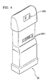
- FIG 2 is a block diagram that shows the constitution of the handy terminal 30, and FIG. 3 and FIG 4 are exterior views of the front side and back side, respectively, of the handy terminal 30.
- the front side is the surface on which a display 305 is provided
- the back side is the surface on the opposite side thereof.
- a CPU 301 is a central processing unit, and by reading a program that is stored in a ROM 302 and executing it, controls the operation of the handy terminal 30.
- the ROM 302 is a read-only memory that stores the aforementioned program.
- a RAM 303 is a random access memory that stores data such as the commodity file that is obtained from, the store controller 10, barcodes of items that are scanned by a scanner portion 304, and its own IP address.
- the scanner portion 304 is for reading barcodes that are attached to commodities, shining light on a barcode to read the barcode by the reflected light, and converting the barcode information that is read to data of a predetermined format to be output. Also, in the state of being mounted on the customer cradle 40, when the handy terminal 30 has received the membership number data that is sent from the membership card reader 50 to its unique IP address, it shines light on an optical sensor b7 of the customer cradle 40 similarly to when reading a barcode.
- This scanner portion 304 is provided on the backside surface of the handy scanner 30, and by bringing a barcode near the scanner portion 304, the scanning operation is performed, The barcode scanning is performed by the customer operation, and the data that is output from the scanner portion 304 is sent to the RAM 303 as data specifying the commodities being purchased, and is stored.
- the display 305 displays the name and price of each commodity whose barcode was read by the scanner portion 304, the list of all scanned commodities, the total amount to be paid, number of purchase points, various messages (for example, guidance on how to use for customers who do not know how to use the handy terminal 30) and the like. Also, an LED portion 305a is provided in the upper center portion of the display 305, with the illumination of this LED portion 305a informing the customer which of the plurality of handy terminals 30 that are mounted in the customer cradle 40 is to be used. When the membership number data is received from the aforementioned membership card reader 50, control is performed so that the LED 305a turns on.
- the control portion 306 consists of various keys for operating the handy terminal 30. As shown in FIG 3 , it has a SCAN key 3061, for starting scanning of a barcode, a CORRECT key 3062 for deleting one at a time commodities whose barcodes have been scanned and correcting the quantities thereof, a CANCEL key for canceling all scanned commodities, a + (plus) key 306 and a - (minus) key for designating the number of commodities to be purchased, up and down arrow keys 3066 for moving up and down the cursor that selects a commodity in the list display of all scanned commodities, and an ENTER key 3067 for selecting an input operation.
- SCAN key 3061 for starting scanning of a barcode
- CORRECT key 3062 for deleting one at a time commodities whose barcodes have been scanned and correcting the quantities thereof
- CANCEL key for canceling all scanned commodities
- + (plus) key 306 and a - (minus) key for designating the number of commodities to be purchased
- a communication portion 307 performs control of data communication between the register cradle 21 and the customer cradle 40. Specifically, when the handy terminal 30 has been connected to the register cradle 21, the data of commodities to be purchased that is stored in the RAM 303 (that is, the data that has been scanned from the barcode of commodities by the scanner portion 304) is sent to the POS register 20 via the register cradle 21. When the handy terminal 30 has been connected to the customer cradle 40, it receives the latest commodity file that is sent from the store controller 10 and the membership number data that is sent from the membership card reader 50. Note that these data communications are carried out in conformance with the RS-232C communication protocol as described above.
- connection terminals 3071 that are provided on the back surface of the handy terminal 30. Also, these connection terminals 3071, beside the aforementioned data communication, also have the application of performing charging of a rechargeable battery 310 when connected to the customer cradle 40.
- a power supply control portion 309 controls charging of the rechargeable battery 310 by electrical power that is supplied from the customer cradle 40 while the handy terminal 30 is connected to the customer cradle 40.
- the rechargeable battery 310 supplies electrical power for driving the components of the handy terminal 30.
- FIGS. 5A to 5C illustrate the customer cradle 40.
- This customer cradle 40 houses one handy terminal 30 per one customer cradle 40, and in the commodity sales processing system as a whole, a plurality of customer cradles 40 are used in order to house a plurality of handy terminals 30.
- FIGS. 5A to 5C illustrate the customer cradle 40.
- the customer cradle 40 has a mounting base body b4 in which any of the handy terminals 30 is mounted on the upper portion, a cover b2 that is constituted to be capable of opening and closing with this mounting base body b4 and covers the handy terminal 30 that is mounted on the mounting base body b4 when being housed, a lock mechanism b10 that locks the opening/closing of the cover b4 in a closed state, an optical sensor b7 that receives light that is radiated from the scanner portion 304 of the handy scanner 30 (provided behind an optical receiving window b8), and a connection terminal b11 for communication between the handy terminal 30 that is mounted on the mounting base body b4 and the store controller 10 or membership card reader 50 via this customer cradle 40 and for charging of the rechargeable battery 310.
- the cover b2 is fixed to the mounting base body b4 so as to freely rotate with an axis b3 serving as a rotation center.
- a plunger b61 is biased by an elastic member not illustrated to project out in the Xa direction from a solenoid b6.
- a pin b5 that is provided at the lower end portion of the cover b2 moves so as to push away a slope that is provided at the end surface of the plunger b61, pushing the plunger b61 in the Xb direction and entering a lock area b62 while forming a gap.
- the plunger b61 is pushed back in the Xa direction by the elastic member, and the cover b2 enters the locked state of being closed.
- the plunger b61 is pulled in the Xb direction by the solenoid b6, creating a space that allows passage of the pin b5 between the plunger b61 and the lock sensor b9.
- the pin b5 leaves the lock area b62 by a biasing force in the opening direction that acts on the cover b2 from an elastic member not illustrated, whereby the cover b2 enters the open state. Note that in the state of the lock sensor b9 not detecting the pin b5, that is, the cover b2 is in a state of not being closed, the solenoid b6 is not driven even if the optical sensor b7 receives an optical signal.
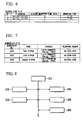
- FIG. 6 is an example of an elapsed time file that the membership card reader 50 stores.
- the elapsed time file keeps track of the passage of time during which each handy terminal 30 is mounted in the customer cradle 40, and consists of various items such as the number of each handy terminal, IP address, elapsed mounting time, mounting time, and the like.
- the IP address is xxx.yyy.zzz.nnn
- the time of being mounted in the customer cradle 40 is 11:15
- the time that has elapsed since mounting is 15 minutes.
- FIG 7 is an example of a membership file that the membership card reader 50 stores.
- the membership file is data in which items such as membership numbers, names, addresses, telephone numbers are expressed in tabular format.
- items such as membership numbers, names, addresses, telephone numbers are expressed in tabular format.
- the name is Taro Nippon
- the address is 1-2-3 Yamanote, Ota-ku, Tokyo
- the telephone number is 03-1234-5678.
- FIG. 8 is a block view that shows the constitution of the membership card reader 50.
- the membership card reader 50 consists of a CPU 201, a ROM 202, a RAM 203, a card reader portion 204, a clock 205, and a communications portion 206.
- the CPU 201 is a central processing unit, and by reading a program that is stored in the ROM 202 and executing it, controls the operation of the membership card reader 50.
- the ROM 202 is a read-only memory that stores the aforementioned program.
- the RAM 203 is a random access memory that stores the elapsed time file of FIG. 6 , the membership file of FIG. 7 , and the commodity file that is obtained from the store controller 10.
- the card reader portion 204 performs reading of membership cards.
- the clock 205 keeps the current time, and the communications portion 206 performs data communication with the handy terminal 30 via the customer cradle 40.
- Step S 1 the card reader portion 204 reads the card information when a membership card is inserted into the membership card reader 50, and the CPU 201 determines whether or not it is a valid membership card by referring to the membership file in the RAM 203.
- Step S2 the CPU 201 selects the handy terminal 30 with the longest elapsed time from among the plurality of handy terminals 30 by referring to the elapsed time file in the RAM 203, and sends from the communications portion 206 the membership number data that was read in Step S 1 to the IP address of the chosen handy terminal 30. This membership number data is sent to the handy terminal 30 via the customer cradle 40.
- Step S3 the handy terminal 30 receives the membership number data that was sent in Step S2 and transmits an optical signal (lock release signal) from the scanner portion 304. Also, the handy terminal 30 causes the LED 305a to emit light, and displays the membership number data that was received on the display 305.
- Step S4 when the optical sensor b7 of the customer cradle 40 receives the optical signal that is emitted from the handy terminal 30, the solenoid b6 operates to release the lock of the closed state of the cover b2, and thereby puts the cover b2 in an open state. As a result, a state arises in which the handy terminal 30 can be taken out.
- the customer finds the handy terminal 30 to be used by confirming the lighting of the LED 305a and the membership number display in the display 305 that were performed in Step S3. The customer then removes that handy terminal 30 from the customer cradle 40 and commences shopping.
- Step S5 the CPU 201 of the membership card reader 50 detects that the handy terminal 30 has been removed from the customer cradle 40 by the loss of contact between the connection terminals 3071 of the handy terminal 30 and a connection terminal b11 of the customers cradle 40 by monitoring the IP address of the handy terminal 30, and clears the elapsed mounting time and mounting time corresponding to the handy terminal 30 that has been removed in the elapsed time file of the RAM 203.
- Step S6 a customer that has finished shopping returns the handy terminal 30.
- the connection terminal b11 of the customer cradle b11 and the connection terminals 3071 of the handy terminal 30 make contact, whereby charging is performed via the connection terminals.
- the CPU 201 of the membership card reader 50 detects the contact of the connection terminals by monitoring the IP address, and records the present time as the mounting time in the elapsed time file of the RAM 203.
- the handy terminal 30 when the handy terminal 30 receives the membership number data that is sent from the membership card reader 50 in the case of a valid membership card, the handy terminal 30 transmits an optical signal (lock release signal), and the customer cradle 40, upon receiving the lock release signal from the handy terminal 30, releases the lock of the handy terminal 30. Therefore, the customer cradle 40 can put the handy terminal 30 in a removable state without communication with the membership card reader 50.
- an optical signal lock release signal
- the customer cradle 40 can use a buzzer sound, electrical signal or wireless signal instead of using an optical signal for releasing the lock of the cover b2.
- the lock unit of the customer cradle 40 was in the form of the cover b2, but is not limited thereto, and may be a lock unit with any structure provided it is one that mechanically prevents removal of the handy terminal 30.
- the membership number data that is sent to the handy terminal 30 may be transmitted from the store controller 10 and not from the membership card reader 50.
- a simple operation button may be provided instead of the membership card reader 50, so that when a customer presses this operation button, a signal for releasing the lock of the customer cradle 40 is transmitted from a communication device that is provided with this operation button to the (whichever) handy terminal 30. Thereby, it is possible to allow even a customer who does not have a membership card to use the handy terminal 30.
Landscapes
- Engineering & Computer Science (AREA)
- Physics & Mathematics (AREA)
- General Physics & Mathematics (AREA)
- Theoretical Computer Science (AREA)
- Computer Networks & Wireless Communication (AREA)
- Computer Hardware Design (AREA)
- Human Computer Interaction (AREA)
- General Engineering & Computer Science (AREA)
- Cash Registers Or Receiving Machines (AREA)
- Management, Administration, Business Operations System, And Electronic Commerce (AREA)
Applications Claiming Priority (1)
| Application Number | Priority Date | Filing Date | Title |
|---|---|---|---|
| JP2007340912A JP2009163403A (ja) | 2007-12-28 | 2007-12-28 | 商品販売処理システム |
Publications (2)
| Publication Number | Publication Date |
|---|---|
| EP2075772A2 true EP2075772A2 (fr) | 2009-07-01 |
| EP2075772A3 EP2075772A3 (fr) | 2010-01-13 |
Family
ID=40351587
Family Applications (1)
| Application Number | Title | Priority Date | Filing Date |
|---|---|---|---|
| EP08172955A Withdrawn EP2075772A3 (fr) | 2007-12-28 | 2008-12-26 | Système de traitement de ventes d'articles |
Country Status (3)
| Country | Link |
|---|---|
| US (1) | US20090166414A1 (fr) |
| EP (1) | EP2075772A3 (fr) |
| JP (1) | JP2009163403A (fr) |
Families Citing this family (6)
| Publication number | Priority date | Publication date | Assignee | Title |
|---|---|---|---|---|
| US8186597B1 (en) * | 2011-02-08 | 2012-05-29 | Hand Held Products, Inc. | Magnetic method for securing a scanner |
| JP2014167787A (ja) * | 2013-02-04 | 2014-09-11 | Toshiba Tec Corp | 商品販売データ処理装置、携帯端末およびプログラム |
| JP6481266B2 (ja) * | 2014-06-19 | 2019-03-13 | 株式会社寺岡精工 | 商品販売データ処理システムおよび商品販売データ処理方法 |
| JP6439928B2 (ja) * | 2014-12-09 | 2018-12-19 | セイコーソリューションズ株式会社 | オーダーエントリーシステム、コントローラ及びプログラム |
| US9979693B2 (en) * | 2016-01-28 | 2018-05-22 | Fiber Logic Communications, Inc. | IP allocation method for use in telecommunication network automatic construction |
| JP7434763B2 (ja) * | 2019-09-11 | 2024-02-21 | 日本電気株式会社 | 店舗管理装置、店舗管理システム、店舗管理方法、コンピュータプログラム及び記録媒体 |
Citations (1)
| Publication number | Priority date | Publication date | Assignee | Title |
|---|---|---|---|---|
| JPH10241045A (ja) | 1997-02-28 | 1998-09-11 | Teraoka Seiko Co Ltd | セルフスキャニングシステム |
Family Cites Families (5)
| Publication number | Priority date | Publication date | Assignee | Title |
|---|---|---|---|---|
| CA2201423C (fr) * | 1997-04-01 | 2007-06-26 | Michael Coveley | Installation de magasinage sans commis ainsi que les elements qui la composent |
| US6409086B1 (en) * | 1997-08-08 | 2002-06-25 | Symbol Technolgies, Inc. | Terminal locking system |
| US6394355B1 (en) * | 1999-02-22 | 2002-05-28 | Symbol Technologies, Inc. | Hand-held acquistion device |
| JP4623971B2 (ja) * | 2002-04-11 | 2011-02-02 | センサーマチック・エレクトロニックス・コーポレーション | 携帯型組み合わせ電子物品監視システムおよびバーコードスキャナを使用して資産を管理するシステムおよび方法 |
| WO2005001610A2 (fr) * | 2003-05-30 | 2005-01-06 | Buchholz Kenneth E | Systeme et procede de realisation de ventes de biens et magasin de detail mettant en oeuvre un tel systeme |
-
2007
- 2007-12-28 JP JP2007340912A patent/JP2009163403A/ja active Pending
-
2008
- 2008-12-26 EP EP08172955A patent/EP2075772A3/fr not_active Withdrawn
- 2008-12-29 US US12/345,185 patent/US20090166414A1/en not_active Abandoned
Patent Citations (1)
| Publication number | Priority date | Publication date | Assignee | Title |
|---|---|---|---|---|
| JPH10241045A (ja) | 1997-02-28 | 1998-09-11 | Teraoka Seiko Co Ltd | セルフスキャニングシステム |
Also Published As
| Publication number | Publication date |
|---|---|
| JP2009163403A (ja) | 2009-07-23 |
| US20090166414A1 (en) | 2009-07-02 |
| EP2075772A3 (fr) | 2010-01-13 |
Similar Documents
| Publication | Publication Date | Title |
|---|---|---|
| US5923735A (en) | Self-service checkout system utilizing portable self-checkout communications terminal | |
| US6687345B1 (en) | Wireless telephone for acquiring data encoded in bar code indicia | |
| US7114656B1 (en) | Fixed self-checkout station with cradle for communicating with portable self-scanning units | |
| US6243447B1 (en) | Self-service checkout system utilizing portable communications terminal | |
| US7010501B1 (en) | Personal shopping system | |
| EP1031936B1 (fr) | Dispositif portatif d'acquisition de données | |
| AU2003299426B2 (en) | Payment system | |
| US8856033B2 (en) | Mobile barcode scanner gun system with mobile tablet device having a mobile POS and enterprise resource planning application for customer checkout/order fulfillment and real time in store inventory management for retail establishment | |
| EP2075772A2 (fr) | Système de traitement de ventes d'articles | |
| JP4858552B2 (ja) | 会計方法及びposシステム | |
| JP2003085623A (ja) | 自動販売機およびその販売方法 | |
| US8038054B2 (en) | Method of using an indicia reader | |
| JP5401787B2 (ja) | 商品販売処理システム | |
| EP1927946A1 (fr) | Système de traitement des ventes de produit | |
| US20050259797A1 (en) | Self-service checkout system utilizing portable communications terminal | |
| US20230138605A1 (en) | Vending machine system | |
| US20230129968A1 (en) | Vending machine system | |
| EP1162583A1 (fr) | Dispositif et système intégré pour la distribution de terminaux portables pour la saisie de données d'articles dans un environnement d'achat, et système intégré pour la vente de produits utilisant des terminaux portables | |
| JP2008293180A (ja) | 商品販売処理システム | |
| JP2023024001A (ja) | 店舗端末装置、情報出力方法、およびプログラム | |
| JP2008293179A (ja) | 商品販売処理システム | |
| JP2008065636A (ja) | セルフオーダーシステム | |
| JP2002533847A (ja) | コンパクトなバーコード・スキャナ | |
| JP5157141B2 (ja) | 商品販売処理システム | |
| JP4593417B2 (ja) | キャッシュレジスタ |
Legal Events
| Date | Code | Title | Description |
|---|---|---|---|
| PUAI | Public reference made under article 153(3) epc to a published international application that has entered the european phase |
Free format text: ORIGINAL CODE: 0009012 |
|
| AK | Designated contracting states |
Kind code of ref document: A2 Designated state(s): AT BE BG CH CY CZ DE DK EE ES FI FR GB GR HR HU IE IS IT LI LT LU LV MC MT NL NO PL PT RO SE SI SK TR |
|
| AX | Request for extension of the european patent |
Extension state: AL BA MK RS |
|
| PUAL | Search report despatched |
Free format text: ORIGINAL CODE: 0009013 |
|
| AK | Designated contracting states |
Kind code of ref document: A3 Designated state(s): AT BE BG CH CY CZ DE DK EE ES FI FR GB GR HR HU IE IS IT LI LT LU LV MC MT NL NO PL PT RO SE SI SK TR |
|
| AX | Request for extension of the european patent |
Extension state: AL BA MK RS |
|
| RIC1 | Information provided on ipc code assigned before grant |
Ipc: G06F 1/16 20060101ALI20091207BHEP Ipc: G07G 1/14 20060101ALI20091207BHEP Ipc: G07G 1/00 20060101AFI20090223BHEP |
|
| 17P | Request for examination filed |
Effective date: 20100709 |
|
| 17Q | First examination report despatched |
Effective date: 20100818 |
|
| AKX | Designation fees paid |
Designated state(s): DE FR SE |
|
| STAA | Information on the status of an ep patent application or granted ep patent |
Free format text: STATUS: THE APPLICATION IS DEEMED TO BE WITHDRAWN |
|
| 18D | Application deemed to be withdrawn |
Effective date: 20101229 |