EP2075809A1 - Kondensator - Google Patents
Kondensator Download PDFInfo
- Publication number
- EP2075809A1 EP2075809A1 EP07829078A EP07829078A EP2075809A1 EP 2075809 A1 EP2075809 A1 EP 2075809A1 EP 07829078 A EP07829078 A EP 07829078A EP 07829078 A EP07829078 A EP 07829078A EP 2075809 A1 EP2075809 A1 EP 2075809A1
- Authority
- EP
- European Patent Office
- Prior art keywords
- valve body
- filter
- cap
- capacitor
- terminal plate
- Prior art date
- Legal status (The legal status is an assumption and is not a legal conclusion. Google has not performed a legal analysis and makes no representation as to the accuracy of the status listed.)
- Withdrawn
Links
- 239000003990 capacitor Substances 0.000 claims abstract description 69
- 239000008151 electrolyte solution Substances 0.000 claims abstract description 25
- 239000013013 elastic material Substances 0.000 claims abstract description 4
- 229920001971 elastomer Polymers 0.000 claims description 12
- 238000007789 sealing Methods 0.000 claims description 8
- 239000004743 Polypropylene Substances 0.000 claims description 6
- 230000002093 peripheral effect Effects 0.000 claims description 6
- -1 polypropylene Polymers 0.000 claims description 6
- 229920001155 polypropylene Polymers 0.000 claims description 4
- 229920000181 Ethylene propylene rubber Polymers 0.000 claims description 2
- VHOQXEIFYTTXJU-UHFFFAOYSA-N Isobutylene-isoprene copolymer Chemical group CC(C)=C.CC(=C)C=C VHOQXEIFYTTXJU-UHFFFAOYSA-N 0.000 claims description 2
- 229920001343 polytetrafluoroethylene Polymers 0.000 claims description 2
- 239000004810 polytetrafluoroethylene Substances 0.000 claims description 2
- 229910052782 aluminium Inorganic materials 0.000 description 9
- XAGFODPZIPBFFR-UHFFFAOYSA-N aluminium Chemical compound [Al] XAGFODPZIPBFFR-UHFFFAOYSA-N 0.000 description 9
- 239000000853 adhesive Substances 0.000 description 8
- 229910052751 metal Inorganic materials 0.000 description 8
- 239000002184 metal Substances 0.000 description 8
- 230000000903 blocking effect Effects 0.000 description 6
- 230000006835 compression Effects 0.000 description 6
- 238000007906 compression Methods 0.000 description 6
- 230000000694 effects Effects 0.000 description 4
- 238000003466 welding Methods 0.000 description 4
- 229920005549 butyl rubber Polymers 0.000 description 3
- 239000011888 foil Substances 0.000 description 2
- 238000004519 manufacturing process Methods 0.000 description 2
- 239000000463 material Substances 0.000 description 2
- 238000000034 method Methods 0.000 description 2
- 239000012466 permeate Substances 0.000 description 2
- 229910001220 stainless steel Inorganic materials 0.000 description 2
- 239000010935 stainless steel Substances 0.000 description 2
- 238000010438 heat treatment Methods 0.000 description 1
- 230000001771 impaired effect Effects 0.000 description 1
- 239000004570 mortar (masonry) Substances 0.000 description 1
- 238000003825 pressing Methods 0.000 description 1
- 230000008929 regeneration Effects 0.000 description 1
- 238000011069 regeneration method Methods 0.000 description 1
- 239000000126 substance Substances 0.000 description 1
- XLYOFNOQVPJJNP-UHFFFAOYSA-N water Substances O XLYOFNOQVPJJNP-UHFFFAOYSA-N 0.000 description 1
Images



Classifications
-
- H—ELECTRICITY
- H01—ELECTRIC ELEMENTS
- H01G—CAPACITORS; CAPACITORS, RECTIFIERS, DETECTORS, SWITCHING DEVICES, LIGHT-SENSITIVE OR TEMPERATURE-SENSITIVE DEVICES OF THE ELECTROLYTIC TYPE
- H01G9/00—Electrolytic capacitors, rectifiers, detectors, switching devices, light-sensitive or temperature-sensitive devices; Processes of their manufacture
- H01G9/004—Details
- H01G9/08—Housing; Encapsulation
- H01G9/12—Vents or other means allowing expansion
-
- H—ELECTRICITY
- H01—ELECTRIC ELEMENTS
- H01G—CAPACITORS; CAPACITORS, RECTIFIERS, DETECTORS, SWITCHING DEVICES, LIGHT-SENSITIVE OR TEMPERATURE-SENSITIVE DEVICES OF THE ELECTROLYTIC TYPE
- H01G11/00—Hybrid capacitors, i.e. capacitors having different positive and negative electrodes; Electric double-layer [EDL] capacitors; Processes for the manufacture thereof or of parts thereof
- H01G11/78—Cases; Housings; Encapsulations; Mountings
- H01G11/80—Gaskets; Sealings
-
- Y—GENERAL TAGGING OF NEW TECHNOLOGICAL DEVELOPMENTS; GENERAL TAGGING OF CROSS-SECTIONAL TECHNOLOGIES SPANNING OVER SEVERAL SECTIONS OF THE IPC; TECHNICAL SUBJECTS COVERED BY FORMER USPC CROSS-REFERENCE ART COLLECTIONS [XRACs] AND DIGESTS
- Y02—TECHNOLOGIES OR APPLICATIONS FOR MITIGATION OR ADAPTATION AGAINST CLIMATE CHANGE
- Y02E—REDUCTION OF GREENHOUSE GAS [GHG] EMISSIONS, RELATED TO ENERGY GENERATION, TRANSMISSION OR DISTRIBUTION
- Y02E60/00—Enabling technologies; Technologies with a potential or indirect contribution to GHG emissions mitigation
- Y02E60/13—Energy storage using capacitors
-
- Y—GENERAL TAGGING OF NEW TECHNOLOGICAL DEVELOPMENTS; GENERAL TAGGING OF CROSS-SECTIONAL TECHNOLOGIES SPANNING OVER SEVERAL SECTIONS OF THE IPC; TECHNICAL SUBJECTS COVERED BY FORMER USPC CROSS-REFERENCE ART COLLECTIONS [XRACs] AND DIGESTS
- Y02—TECHNOLOGIES OR APPLICATIONS FOR MITIGATION OR ADAPTATION AGAINST CLIMATE CHANGE
- Y02T—CLIMATE CHANGE MITIGATION TECHNOLOGIES RELATED TO TRANSPORTATION
- Y02T10/00—Road transport of goods or passengers
- Y02T10/60—Other road transportation technologies with climate change mitigation effect
- Y02T10/70—Energy storage systems for electromobility, e.g. batteries
Definitions
- the present invention relates to a capacitor having a pressure control valve with a stable operating pressure and being excellent in safety.
- Fig. 8 is a sectional view showing a conventional capacitor
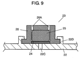
- Fig. 9 is a sectional view showing a configuration of pressure control valve 23 provided in the capacitor.
- This capacitor includes capacitor element 20 provided with hollow 20A.
- Capacitor element 20 includes a pair of positive and negative electrodes, each in which a polarizable electrode layer is formed on an aluminum foil current collector, and a separator interposed therebetween (any of them are not shown).
- the positive and negative electrodes are wound in such a manner that they are displaced from each other in the opposite direction (in the vertical direction in Fig. 8 ). From both ends (upper and lower ends in Fig. 8 ) of capacitor element 20, positive and negative electrodes are electrically led out, respectively.
- Case 21 which has a cylindrical shape with a bottom and is made of a metal such as aluminum, accommodates capacitor element 20 together with an electrolyte solution (not shown).
- Negative terminal 21A for external connection is provided integrally with the outer bottom surface of case 21.
- Protrusion 21B is provided integrally with the inner bottom surface of case 21 so that it is fitted into hollow 20A. After protrusion 21B is fitted into hollow 20A, the end on the side of the negative electrode of capacitor element 20 that has been inserted into case 21 is bonded to the inner bottom surface of case 21 mechanically and electrically by, for example, laser welding.
- Positive terminal 22A for external connection is provided integrally with the outer surface side of aluminum sealing plate 22.
- Protrusion 22B is fitted into hollow 20A.
- Hole 22C is provided in order to pour the electrolyte solution into case 21.
- Pressure control valve 23 is provided so as to close hole 22C.
- the end on the side of the positive electrode of capacitor element 20 is bonded to the inner surface of sealing plate 22 mechanically and electrically by, for example, laser welding.
- case 21 is sealed by performing a processing (curling processing) so that the peripheral edge of sealing plate 22 wraps the opening portion of case 21.
- pressure control valve 23 includes gas permeable member 24, blocking body 25 and cap 26.
- Gas permeable member 24 and blocking body 25 are disposed on hole 22C.
- Metal cap 26 is provided with hole 26A that communicates with outside. Cap 26 is fixed so as to cover them and presses blocking body 25 in the direction in which blocking body 25 always blocks hole 26A.
- Annular convex part 22D is provided on sealing plate 22 so that it surrounds the periphery of hole 22C. Cap 26 is fixed by deforming convex part 22D by, for example, caulking and pressing it to cap 26.
- Pressure control valve 23 releases a gas generated inside the capacitor to the outside when the internal pressure of the capacitor is a predetermined pressure or more. Thus, the pressure inside the capacitor is prevented from increasing. Furthermore, after operation, pressure control valve 23 returns to the state before operation so as to maintain the airtightness inside the capacitor. That is to say, pressure control valve 23 is a self-returning type valve. Therefore, even if the internal pressure is increased due to the generation of gas inside the capacitor, the appearance of the capacitor is not affected, and the property can be maintained.
- pressure control valve 23 includes gas permeable member 24.
- Gas permeable member 24 is formed of a material capable of preventing permeation of the electrolyte solution and allowing a gas generated inside the capacitor to permeate to the outside.
- gas permeable member 24 By bringing gas permeable member 24 into close contact with the periphery of hole 22C of sealing plate 22, it is possible to prevent the function of pressure control valve 23 from being impaired due to contact of the electrolyte solution with blocking body 25.
- Such a capacitor is disclosed in, for example, Patent document 1.
- pressure control valve 23 is placed with respect to hole 22C for pouring an electrolyte solution into the case.
- pressure control valve 23 is placed by directly incorporating each member on hole 22C after a capacitor is fabricated and an electrolyte solution is poured from hole 22C. Therefore, a variation in the fabrication accuracy of pressure control valve 23 leads to a variation in the operation of pressure control valve 23.
- an amount of compression of blocking body 25 is directly linked to an operating pressure of pressure control valve 23, the variation in the operating pressure of pressure control valve 23 easily occurs.
- the present invention provides a capacitor having a pressure control valve with a stable operating pressure.
- the capacitor of the present invention includes a capacitor element, an electrolyte solution, a case, a terminal plate, a filter, a valve body and a cap.
- the capacitor element includes a positive electrode, a negative electrode facing the positive electrode, a separator interposed between the positive and negative electrodes.
- the capacitor element is impregnated with the electrolyte solution.
- the case having an opening accommodates the capacitor element and the electrolyte solution.
- the terminal plate provided with a first hole seals the opening of the case.
- the filter is provided so as to close the first hole and is composed of a gas permeable sheet capable of preventing permeation of an electrolyte solution.
- the valve body formed of an elastic material has a cylindrical part and a bottom part, and is disposed so that the bottom part covers the filter.
- the cap provided with a second hole is fixed to the terminal plate, covers the valve body, and holds the valve body in a state in which it compresses the valve body with respect to the terminal plate.
- the valve body and the filter are provided apart from each other.
- the filter, the valve body, and the cap constitute a pressure control valve.
- the capacitor employing this pressure control valve has a constant operating pressure in a wide range of compression ratio and is capable of repeating operations. Therefore, the capacitor having this pressure control valve can improve the reliability and the safety.
- Fig. 1 is a sectional view showing a capacitor in accordance with a first exemplary embodiment of the present invention.
- This capacitor includes capacitor element 1, metal case 3, terminal plate 4 and pressure control valve 5.
- Capacitor element 1 includes a pair of positive and negative electrodes, each in which a polarizable electrode layer is formed on an aluminum foil current collector, and a separator interposed therebetween (any of them are not shown).
- the positive and negative electrodes are wound in such a manner that they are displaced from each other in the opposite direction (in the vertical direction in Fig. 1 ). From both ends (upper and lower ends in Fig. 1 ) of capacitor element 1, the positive and negative electrodes are electrically led out, respectively.
- Case 3 which has a cylindrical shape with a bottom and is made of a metal such as aluminum, accommodates capacitor element 1 together with an electrolyte solution (not shown). Capacitor element 1 is impregnated with the electrolyte solution. The end on the negative electrode side of capacitor element 1 that has been inserted into case 3 is bonded to the inner bottom surface of case 3 mechanically and electrically by, for example, laser welding. According to this configuration, case 3 also serves as a lead-out electrode on the side of the negative electrode of capacitor element 1.
- Terminal plate 4 made of metal such as aluminum is provided with through-hole 4A as a first hole used for pouring an electrolyte solution into case 3.
- the end on the side of the positive electrode of capacitor element 1 is bonded to the inner surface of terminal plate 4 mechanically and electrically by, for example, laser welding.
- Case 3 is sealed by performing a processing such as curling so that the peripheral edge of terminal plate 4 wraps an opening of case 3 with insulating member 9 intervened in the peripheral edge of terminal plate 4 and the opening of case 3. That is to say, terminal plate 4 seals the opening of case 3.
- Terminal plate 4 serves as a lead-out electrode on the side of the positive electrode.
- Pressure control valve 5 is provided on through-hole 4A of the thus configured terminal plate 4. When a gas is generated due to a reaction of the electrolyte solution and the like, and the internal pressure is abnormally increased, the pressure can be released via pressure control valve 5.
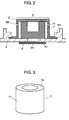
- Fig. 2 is a sectional view showing pressure control valve 5
- Fig. 3 is a perspective view showing valve body 7.
- Pressure control valve 5 includes filter 6, valve body 7 and cap 8.
- Filter 6 is composed of a gas permeable sheet.
- Filter 6 has a property of allowing a gas generated under terminal plate 4 to permeate and preventing permeation of the electrolyte solution.
- a porous film of polytetrafluoroethylene can be used.
- Filter 6 is fixed to terminal plate 4 with an adhesive agent and the like on the lower surface of through-hole 4A provided in terminal plate 4 (inner side of case 3).
- filter 6 may be fixed by disposing denatured polypropylene (not shown) between filter 6 and terminal plate 4 and heat-sealing thereof.
- Valve body 7 formed of an elastic material such as butyl rubber is disposed so that its central axis is substantially identical to the central axis of through-hole 4A.
- Metal cap 8 is provided with vent holes 8A as second holes that communicates to the outside.
- Valve body 7 is disposed so as to close through-hole 4A. That is to say, valve body 7 is provided so as to cover filter 6 and apart from filter 6.
- Cap 8 made of a metal such as stainless steel covers valve body 7 and holds valve body 7 in a state in which it compresses valve body 7.
- Cap 8 is fixed by convex part 4B provided on terminal plate 4.
- valve body 7 when the internal pressure of case 3 shown in Fig. 1 is abnormally increased, valve body 7 is pushed upward and only the gas passes through filter 6 and through-hole 4A and is released from vent holes 8A to the outside. Therefore, the pressure can be released via pressure control valve 5 without leakage of the electrolyte solution accommodated in case 3.
- valve body 7 and filter 6 are provided apart from each other.
- Metal terminal plate 4 is more rigid and has higher dimensional accuracy as compared with filter 6. Therefore, a variation in the amount of compression of valve body 7 is reduced and a variation in the operating pressure of pressure control valve 5 is also reduced.
- a capacitor having a higher safety and in which leakage of the electrolyte solution does not occur even if the pressure is abnormally increased inside case 3 can be produced stably.
- valve body 7 has a cylindrical shape with a bottom, which includes cylindrical part 71 and bottom part 72 as shown in Figs. 2 and 3 .
- Valve body 7 is disposed so that bottom part 72 covers filter 6.
- Valve body 7 closes through-hole 4A in a form in which cylindrical part 71 is slightly buckling because valve body 7 is pressed by cap 8.
- Upper surface part 7A of valve body 7 is substantially in parallel to the bottom surface.
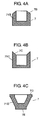
- FIGS. 4A through 4C are sectional views showing more preferable shapes of valve body 7.
- Cylindrical part 71B of valve body 7 shown in Fig. 4A has upper surface part 7B in a part that is brought into contact with cap 8.
- Upper surface part 7B has a so-called taper shape in which the height is gradually reduced from the center to the outer side of cylindrical part 71B.
- cylindrical part 71C of valve body 7 shown in Fig. 4B has upper surface part 7C in a part that is brought into contact with cap 8.
- Upper surface part 7C has a taper shape in which the height is gradually increased from the center to the outer side of the cylinder, contrarily to Fig. 4A .
- cylindrical part 71D of valve body 7 shown in Fig. 4C has upper surface part 7D in a part that is brought into contact with cap 8.
- the diameter of bottom part 7E is smaller than the diameter (outer diameter) of upper surface part 7D.
- Cylindrical part 71D is formed in a mortar shape. Thus, the wall surface of valve body 7 buckles in such a manner that it bends downward.
- valve bodies 7 By using any of these valve bodies 7, it is possible to control the buckling state of valve body 7. That is to say, even if the amount of compression of valve body 7 is somewhat changed, the stress in the vertical direction can be more stabilized. Consequently, it is possible to stabilize the operating pressure of pressure control valve 5.
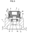
- Fig. 5 is a sectional view showing a pressure control valve used in a capacitor in accordance with a second exemplary embodiment of the present invention.
- Fig. 6 is an exploded sectional view of the pressure control valve shown in Fig. 5 .
- the capacitor of this exemplary embodiment includes terminal plate 4 and pressure control valve 5 having different structure of pressure control valve 5 of the first exemplary embodiment. Since the other basic configurations are the same as those of the first exemplary embodiment, only pressure control valve 5 and terminal plate 4 are described and the description of the other components is omitted herein. Note that the same reference numerals are given to the components having the same configuration as those in the first exemplary embodiment and the detailed description thereof may be omitted.
- Pressure control valve 5 of this exemplary embodiment includes valve unit 17, filter unit 19 and presser rubber 12. Firstly, valve unit 17 is described. Valve unit 17 includes valve body 7, cap 8 and washer 16 as a first washer.
- Valve body 7 is composed of butyl rubber and formed in a cylindrical shape with a bottom as in the first exemplary embodiment.
- Flange 8B is provided at an opening end of cap 8 having a cylindrical shape with a bottom.
- Washer 16 is formed of aluminum and provided with hole 16A at the center thereof.
- annular wall part 16B is provided integrally with the peripheral edge of the upper surface of washer 16.
- Valve unit 17 is fabricated by mounting valve body 7 on washer 16 and press-fitting washer 16 into cap 8. At this time, valve body 7 is held in a compressed state. Note here that in order to press fit washer 16 into cap 8, a jig (not shown) is used. Thus, it is possible to manage the press-fitting dimension accurately. Furthermore, valve body 7 can be positioned with respect to cap 8 accurately by providing washer 16 with wall part 16B.
- At least a part of cylindrical part 8D of cap 8 is provided with a notch and that this notch is processed to protrude to the inside of cap 8 so as to provide cut-and-raised part 8C.
- Circular filter unit 19 includes filter 6, adhesive agent 6A and washer 18 as a second washer.
- Aluminum washer 18 is provided with hole 18A in the center thereof.
- Filter 6 is formed of the same material as that of the first exemplary embodiment.
- Adhesive agent 6A is also formed of, for example, film-like denatured polypropylene (hereinafter, referred to as "denatured PP") as described in the first exemplary embodiment.
- Filter 6 and washer 18 are bonded to each other by heat-sealing with the use of adhesive agent 6A.
- Filter unit 19 is disposed on through-hole 4A for pouring an electrolyte solution therethrough provided in terminal plate 4.
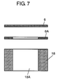
- Fig. 7 is an exploded sectional view of filter unit 19, which shows a method of bonding washer 18 and filter 6 to each other by using adhesive agent 6A composed of denatured PP.
- washer 18 and filter 6 are superimposed on each other with adhesive agent 6A disposed therebetween, followed by heating at 140 to 200°C for about 10 seconds and press-working at a pressure of 1 kgf/cm 2 .
- adhesive agent 6A is uniformly impregnated into filter 6 to generate an anchor effect by which filter 6 and washer 18 are bonded to each other.
- Cylindrical presser rubber 12 made of butyl rubber includes flat part 12B provided with hole 12A in the center thereof and wall part 12C made in the peripheral part of flat part 12B.
- a procedure for fabricating pressure control valve 5 on terminal plate 4 by using the thus configured valve unit 17, filter unit 19 and presser rubber 12 is described.
- filter unit 19 is disposed on the upper side (outer side) of through-hole 4A provided in terminal plate 4.
- presser rubber 12 is put so as to cover filter unit 19.
- presser rubber 12 is disposed so that wall part 12C surrounds filter unit 19.
- valve unit 17 is disposed on presser rubber 12.
- caulking protrusion 4D provided on terminal plate 4 protrusion 4D is press-contacted to flange 8B of cap 8.
- cap 8 and terminal plate 4 are mechanically coupled to each other.
- caulking is carried out so that presser rubber 12 is held in a compressed state.
- valve body 7 is incorporated into valve unit 17 and filter 6 is incorporated into filter unit 19, respectively.
- valve unit 17 in which valve body 7 is held in a compressed state is fabricated. Therefore, the fabrication accuracy of valve unit 17 is improved and a variation in an amount of compression of valve body 7 is reduced. That is to say, also in pressure control valve 5 of this exemplary embodiment, valve body 7 and filter 6 are provided apart from each other. Furthermore, by using valve body 7 having a cylindrical shape with a bottom, the same effect as that in the first exemplary embodiment can be obtained. Thus, a variation in the operation of pressure control valve 5 is reduced. Furthermore, the operation of pressure control valve 5 can be checked by checking valve unit 17 alone. Note here that it is preferable that any of valve bodies 7 shown in Figs. 4A to 4C is used because the same effect as in the first exemplary embodiment can be obtained.
- case 3 and terminal plate 4 serve as lead-out electrodes of the electrodes of capacitor element 1, respectively.
- lead-out electrodes may be provided by using lead wires and the like from capacitor element 1.
- valve body 7 is formed of ethylene propylene rubber because oil resistance, chemical resistance, and the like, are improved. Furthermore, it is further preferable that valve body 7 is formed of isoprene isobutylene rubber because water resistance is also improved in addition to the above-mentioned effects.
- a capacitor using a pressure control valve of the present invention In a capacitor using a pressure control valve of the present invention, a variation in the operating pressure of the pressure control valve is reduced, and therefore the reliability of the operating pressure is improved. As a result, the reliability of the capacitor using the pressure control valve is also improved.
- Such a capacitor is useful for various electronic equipments, for a system of automobile requiring a high reliability under a large current such as regeneration in hybrid cars, and for storing electric power.
Landscapes
- Engineering & Computer Science (AREA)
- Power Engineering (AREA)
- Microelectronics & Electronic Packaging (AREA)
- Electric Double-Layer Capacitors Or The Like (AREA)
- Gas Exhaust Devices For Batteries (AREA)
Applications Claiming Priority (3)
| Application Number | Priority Date | Filing Date | Title |
|---|---|---|---|
| JP2006281089A JP5181454B2 (ja) | 2006-10-16 | 2006-10-16 | コンデンサ |
| JP2007033182 | 2007-02-14 | ||
| PCT/JP2007/069339 WO2008047597A1 (en) | 2006-10-16 | 2007-10-03 | Condenser |
Publications (2)
| Publication Number | Publication Date |
|---|---|
| EP2075809A1 true EP2075809A1 (de) | 2009-07-01 |
| EP2075809A4 EP2075809A4 (de) | 2014-09-17 |
Family
ID=39313838
Family Applications (1)
| Application Number | Title | Priority Date | Filing Date |
|---|---|---|---|
| EP07829078.0A Withdrawn EP2075809A4 (de) | 2006-10-16 | 2007-10-03 | Kondensator |
Country Status (4)
| Country | Link |
|---|---|
| US (1) | US7916454B2 (de) |
| EP (1) | EP2075809A4 (de) |
| KR (1) | KR100963730B1 (de) |
| WO (1) | WO2008047597A1 (de) |
Families Citing this family (12)
| Publication number | Priority date | Publication date | Assignee | Title |
|---|---|---|---|---|
| WO2008099578A1 (ja) * | 2007-02-14 | 2008-08-21 | Panasonic Corporation | コンデンサ |
| JP4959657B2 (ja) * | 2008-09-19 | 2012-06-27 | 東芝照明プレシジョン株式会社 | 封口装置及び密閉容器 |
| KR101228700B1 (ko) * | 2009-05-14 | 2013-02-01 | 파나소닉 주식회사 | 커패시터 |
| CN103081047B (zh) * | 2010-08-18 | 2017-07-04 | 日本贵弥功株式会社 | 电容器、电容器的制造方法以及制造程序 |
| WO2013001821A1 (ja) | 2011-06-28 | 2013-01-03 | 日本ケミコン株式会社 | 蓄電デバイスおよび蓄電デバイスの製造方法 |
| CN103946939B (zh) * | 2011-11-17 | 2017-02-15 | 日本贵弥功株式会社 | 电容器及其制造方法 |
| JP6278176B2 (ja) * | 2013-06-05 | 2018-02-14 | 日本ケミコン株式会社 | ガス抜き弁を設けた蓄電デバイスの製造方法 |
| CN105308699B (zh) * | 2013-06-14 | 2018-04-06 | 日本贵弥功株式会社 | 电容器 |
| DE102015119844B4 (de) * | 2015-11-17 | 2025-01-02 | Tdk Electronics Ag | Elektrolytischer Kondensator mit Sicherheitsentlüftung |
| US10128055B1 (en) * | 2017-07-31 | 2018-11-13 | Lelon Electronics Corp. | Electrolytic capacitor |
| JP7247741B2 (ja) * | 2019-05-16 | 2023-03-29 | 株式会社豊田自動織機 | 圧力調整弁の製造方法、及び蓄電モジュール |
| CN213393710U (zh) * | 2020-07-14 | 2021-06-08 | 东莞东阳光科研发有限公司 | 泄压阀及具有其的电解电容器 |
Family Cites Families (10)
| Publication number | Priority date | Publication date | Assignee | Title |
|---|---|---|---|---|
| GB1445807A (en) * | 1974-03-27 | 1976-08-11 | Erie Electronics Ltd | Electrical capacitors |
| JPS59127366A (ja) * | 1983-01-07 | 1984-07-23 | Matsushita Electric Ind Co Ltd | 電池の安全弁 |
| JP2000195761A (ja) | 1998-12-28 | 2000-07-14 | Elna Co Ltd | コンデンサ用安全弁装置 |
| JP2000315632A (ja) | 1999-03-02 | 2000-11-14 | Matsushita Electric Ind Co Ltd | コンデンサ |
| JP3673671B2 (ja) | 1999-06-01 | 2005-07-20 | 有限会社武蔵野技研 | ガス抜き弁 |
| JP4132588B2 (ja) * | 2000-06-16 | 2008-08-13 | Tdk株式会社 | 電気化学デバイス |
| JP2003100571A (ja) | 2001-09-26 | 2003-04-04 | Power System:Kk | 電気二重層キャパシタ |
| JP4003604B2 (ja) | 2002-10-11 | 2007-11-07 | 松下電器産業株式会社 | コンデンサおよびその製造方法 |
| JP2005183754A (ja) | 2003-12-22 | 2005-07-07 | Nok Corp | 圧力開放弁 |
| JP2006156868A (ja) * | 2004-12-01 | 2006-06-15 | Nok Corp | 圧力開放弁 |
-
2007
- 2007-10-03 US US12/067,881 patent/US7916454B2/en not_active Expired - Fee Related
- 2007-10-03 WO PCT/JP2007/069339 patent/WO2008047597A1/ja not_active Ceased
- 2007-10-03 EP EP07829078.0A patent/EP2075809A4/de not_active Withdrawn
- 2007-10-03 KR KR1020087006599A patent/KR100963730B1/ko not_active Expired - Fee Related
Also Published As
| Publication number | Publication date |
|---|---|
| US7916454B2 (en) | 2011-03-29 |
| US20100149728A1 (en) | 2010-06-17 |
| WO2008047597A1 (en) | 2008-04-24 |
| EP2075809A4 (de) | 2014-09-17 |
| KR100963730B1 (ko) | 2010-06-14 |
| KR20080057243A (ko) | 2008-06-24 |
Similar Documents
| Publication | Publication Date | Title |
|---|---|---|
| EP2075809A1 (de) | Kondensator | |
| US8737041B2 (en) | Capacitor and method of manufacturing the same | |
| CN116670922A (zh) | 圆柱形二次电池 | |
| JP2005520344A (ja) | コップ形ケーシング及びケーシングを有するコンデンサ | |
| JP5083220B2 (ja) | コンデンサ | |
| CN116895820A (zh) | 圆柱形二次电池 | |
| CN114342023A (zh) | 具有用于气体扩散的控制元件的电解电容器 | |
| JP2001102025A (ja) | 密閉型電池 | |
| JP2009194131A (ja) | キャパシタ | |
| JP2011187773A (ja) | キャパシタ | |
| CN101356609B (zh) | 电容器 | |
| JP4613728B2 (ja) | コンデンサ | |
| US7442467B2 (en) | Sealed battery | |
| JP5167926B2 (ja) | キャパシタ | |
| JP4613729B2 (ja) | コンデンサ | |
| JP2009266873A (ja) | キャパシタ | |
| JP2008177322A (ja) | キャパシタ | |
| JP4613731B2 (ja) | コンデンサ | |
| JP4613733B2 (ja) | コンデンサ | |
| JP4613730B2 (ja) | コンデンサ | |
| JP4613732B2 (ja) | コンデンサ | |
| CN104620421A (zh) | 具有带粘接的封闭塞的壳体盖板的电池单元 | |
| JP2019179664A (ja) | 蓄電素子の製造方法及び蓄電素子 | |
| JP2007335775A (ja) | コンデンサ | |
| JP2010087286A (ja) | 電解コンデンサ |
Legal Events
| Date | Code | Title | Description |
|---|---|---|---|
| PUAI | Public reference made under article 153(3) epc to a published international application that has entered the european phase |
Free format text: ORIGINAL CODE: 0009012 |
|
| 17P | Request for examination filed |
Effective date: 20080325 |
|
| AK | Designated contracting states |
Kind code of ref document: A1 Designated state(s): AT BE BG CH CY CZ DE DK EE ES FI FR GB GR HU IE IS IT LI LT LU LV MC MT NL PL PT RO SE SI SK TR |
|
| AX | Request for extension of the european patent |
Extension state: AL BA HR MK RS |
|
| DAX | Request for extension of the european patent (deleted) | ||
| RBV | Designated contracting states (corrected) |
Designated state(s): DE FR IT |
|
| A4 | Supplementary search report drawn up and despatched |
Effective date: 20140819 |
|
| RIC1 | Information provided on ipc code assigned before grant |
Ipc: H01G 9/12 20060101AFI20140812BHEP |
|
| STAA | Information on the status of an ep patent application or granted ep patent |
Free format text: STATUS: THE APPLICATION IS DEEMED TO BE WITHDRAWN |
|
| 18D | Application deemed to be withdrawn |
Effective date: 20150317 |