EP2076157B1 - Dispositifs de dispersion pour agrégats - Google Patents
Dispositifs de dispersion pour agrégats Download PDFInfo
- Publication number
- EP2076157B1 EP2076157B1 EP07871147.0A EP07871147A EP2076157B1 EP 2076157 B1 EP2076157 B1 EP 2076157B1 EP 07871147 A EP07871147 A EP 07871147A EP 2076157 B1 EP2076157 B1 EP 2076157B1
- Authority
- EP
- European Patent Office
- Prior art keywords
- conduit
- obstacle
- obstacles
- cells
- hole
- Prior art date
- Legal status (The legal status is an assumption and is not a legal conclusion. Google has not performed a legal analysis and makes no representation as to the accuracy of the status listed.)
- Active
Links
Images



Classifications
-
- C—CHEMISTRY; METALLURGY
- C12—BIOCHEMISTRY; BEER; SPIRITS; WINE; VINEGAR; MICROBIOLOGY; ENZYMOLOGY; MUTATION OR GENETIC ENGINEERING
- C12M—APPARATUS FOR ENZYMOLOGY OR MICROBIOLOGY; APPARATUS FOR CULTURING MICROORGANISMS FOR PRODUCING BIOMASS, FOR GROWING CELLS OR FOR OBTAINING FERMENTATION OR METABOLIC PRODUCTS, i.e. BIOREACTORS OR FERMENTERS
- C12M43/00—Combinations of bioreactors or fermenters with other apparatus
- C12M43/02—Bioreactors or fermenters combined with devices for liquid fuel extraction; Biorefineries
-
- C—CHEMISTRY; METALLURGY
- C12—BIOCHEMISTRY; BEER; SPIRITS; WINE; VINEGAR; MICROBIOLOGY; ENZYMOLOGY; MUTATION OR GENETIC ENGINEERING
- C12M—APPARATUS FOR ENZYMOLOGY OR MICROBIOLOGY; APPARATUS FOR CULTURING MICROORGANISMS FOR PRODUCING BIOMASS, FOR GROWING CELLS OR FOR OBTAINING FERMENTATION OR METABOLIC PRODUCTS, i.e. BIOREACTORS OR FERMENTERS
- C12M47/00—Means for after-treatment of the produced biomass or of the fermentation or metabolic products, e.g. storage of biomass
- C12M47/06—Hydrolysis; Cell lysis; Extraction of intracellular or cell wall material
-
- C—CHEMISTRY; METALLURGY
- C12—BIOCHEMISTRY; BEER; SPIRITS; WINE; VINEGAR; MICROBIOLOGY; ENZYMOLOGY; MUTATION OR GENETIC ENGINEERING
- C12N—MICROORGANISMS OR ENZYMES; COMPOSITIONS THEREOF; PROPAGATING, PRESERVING, OR MAINTAINING MICROORGANISMS; MUTATION OR GENETIC ENGINEERING; CULTURE MEDIA
- C12N5/00—Undifferentiated human, animal or plant cells, e.g. cell lines; Tissues; Cultivation or maintenance thereof; Culture media therefor
- C12N5/06—Animal cells or tissues; Human cells or tissues
- C12N5/0602—Vertebrate cells
- C12N5/0603—Embryonic cells ; Embryoid bodies
-
- C—CHEMISTRY; METALLURGY
- C12—BIOCHEMISTRY; BEER; SPIRITS; WINE; VINEGAR; MICROBIOLOGY; ENZYMOLOGY; MUTATION OR GENETIC ENGINEERING
- C12N—MICROORGANISMS OR ENZYMES; COMPOSITIONS THEREOF; PROPAGATING, PRESERVING, OR MAINTAINING MICROORGANISMS; MUTATION OR GENETIC ENGINEERING; CULTURE MEDIA
- C12N2531/00—Microcarriers
Definitions
- the present invention relates to flow-through dispersion devices for dispersion of aggregates, especially of culture suspensions containing cell aggregates.
- the present invention provides flow-through methods for dispersing aggregates to release individual cells.
- the present invention further relates to flow-through methods for homogenization of animal cells suspensions containing cell aggregates.
- Cells are mainly cultured for two applications. Firstly, cell amplification by subculture will result in increases in biomass production of viable cells. These viable cells can be used for such as cell therapies, for viral infections and to obtain infected cells and the like.
- the second application is in producing and isolating biological compounds of interest typically, but not always, present inside the cells, such as polynucleotides, proteins, animal pathogens, or fragments thereof. These bioproducts can also be incorporated into other products like DNA vaccines, subunit vaccines, viral vaccines, gene therapy compositions, drugs and the like.
- a major problem of the cell culture is the formation of cell aggregates formed during the culture.
- Cell aggregates by limiting access of the cells to nutrients and by contact growth inhibition, reduces the culture yield in terms of biomass production and of compounds of interest.
- cell aggregation increases cell death, primarily due to apoptosis. For biomass production harvested cells must not be dead or dying to provide for optimal subculturing.
- a cell aggregate or cluster is a mass of variable size, sometimes visible by the naked eye, formed by the union of individual cells together or by the union of cells to at least one other material (i.e. debris, extracellular matrix) present in the initial cell suspension.
- a cell aggregate has a minimal size of about 800 ⁇ m, in particular a minimal size of about 600 ⁇ m, particularly of about 400 ⁇ m, preferably of about 200 ⁇ m, more preferably of about 100 ⁇ m.
- Dislodged and dispersed cell suspensions may also need to undergo several downstream treatments, for example to remove chemical compounds used during cell harvest, such as trypsin. These steps are time consuming and increase the cost of the product and may result in undesirable reaggregation. For example, a centrifugation step may be performed to remove undesired chemical compounds. This process, however, leads to the formation of a supernatant containing the chemical compounds and which will be discarded, and a pellet comprising cells to be harvested. When compacted into a pellet, the cells are so close and pushed together that cell aggregates are formed.
- chemical compounds used during cell harvest such as trypsin.
- Shear sensitivity is also related to the cell type (i.e. whether thay are fibroblasts, lung cells, kidney cells, etc.), the culture age and history (old cultures having a high number of passages contain more fragile cells) and maintenance conditions (variations of the culture conditions, such as temperature, osmotic pressure, etc generate stresses). Virus infection may also lead to an increase of the shear sensitivity of infected cells.
- shear forces applied on a cell suspension could result in a decrease in cell viability.
- Shearing forces may decrease the yield of the viable cells and can also reduce the ability of the cells to divide by inhibition of cell mitosis.
- Known cell culture manipulation methods may involve dispersion with gentle methods, for example with gentle pipetting (ECACC Handbook, Fundamental Techniques in Cell Culture. A Laboratory Handbook, "Protocol 5 - Subculture of suspension cell lines", 2005, edited by Sigma-Aldrich). Pipetting is typically performed manually by repeated aspiration and rejection of the cell suspension until cell clusters have all disappeared. This manual operation is not, however, consistent and reproducible. Different results can be seen using the same cell culture starting material from one pipette to another, or one operator to another. In addition, shear damage is a function of both shearing time and shearing forces. Pipetting too vigorous and/or over too long a period can damage the cells and result in low viability.
- the present invention addresses these problems by providing a flow-through dispersion device for dispersion of shear sensitive aggregates, notably culture suspensions containing cell aggregates, while respecting the integrity of the individual cells and flow-through methods for dispersing shear-sensitive cell aggregates to release individual cells.
- the present invention encompasses a flow-through dispersion device for the dispersion of cell aggregates, the device comprising an upstream inlet at one extremity of a conduit, a first or upstream inlet obstacle within the conduit, this upstream inlet obstacle having at least one traversing hole that provides from about 50% to about 99.9% of obstruction of the internal cross-section of the conduit, a second or downstream outlet obstacle inside the conduit, this downstream outlet obstacle having at least one traversing hole providing from about 50% to about 99.9% of obstruction of the internal cross-section of the conduit, wherein the longitudinal axis of any hole through any obstacle does not align with the longitudinal axis of any hole of a preceding or succeeding obstacle, and wherein the distance between two successive obstacles is from about 0.1 to about 10 times the diameter of the smallest hole of either of two successive obstacles, and a downstream outlet at the other extremity of the conduit; and wherein the inlet to the device conduit and the upstream inlet obstacle form a first portion of the device, and the outlet to the device conduit and the downstream outlet obstacle form
- the various embodiments of the device according to the invention encompass, but are not limited to, a first obstacle inside the conduit that may be perpendicular to the direction of the flow circulating through this conduit, this first obstacle having a plurality of holes that may be of any configuration including, but not limited to, circular, ovoid, concentric, rectilinear and parallel to the longitudinal axis of the conduit, and which provide from about 50% to about 99.9% obstruction of the section of the conduit, and at least a second obstacle, also inside the conduit and perpendicular to the direction of the flow circulating through this conduit.
- This second obstacle may also have a plurality of holes that may be of any configuration including, but not limited to, circular, concentric, rectilinear and parallel to the longitudinal axis of the conduit that create from about 50% to about 99.9% obstruction of the section of the conduit.
- the holes of the second obstacle are not placed in the same longitudinal alignment as any hole of the first obstacle, and the distance between the first and second obstacles is from about 0.1 to about 10 times the diameter of one hole.
- the device may comprise an upstream inlet at one extremity of a cylindrical-shaped conduit, a first obstacle and a second obstacle inside the conduit and perpendicular to the direction of the flow circulating through this conduit, each obstacle having 3 traversing holes the longitudinal axes of which are parallel to the longitudinal axis of the conduit, and which create about 98% of obstruction of the section of the conduit, the longitudinal axes of the holes of the second obstacle not being in the same longitudinal alignment as the longitudinal axis of any hole of the first obstacle, wherein the distance between the two obstacles is about twice the diameter of the smallest hole of either obstacle, and a downstream outlet at the other extremity of the conduit.
- the present invention further provides a flow-through method for dispersion of aggregates, comprising the steps of (1) flowing of a suspension containing cell aggregates through a dispersion device according to the invention, thereby disrupting the aggregates, optionally repeating step (1) by reflowing the suspension through the device or by placing in series more than one of the flow-through dispersion devices according to the invention, and (4) harvesting the suspension containing individual cells.
- a further object of the invention is to provide a method of cell culture, comprising the steps of (1) introducing cells to be cultured into a culture batch filled with a culture medium and culturing the cells, (2) flowing the suspension containing cell aggregates obtained in step (1) through at least one flow-through dispersion device according to the invention, thereby disrupting the aggregates, (3) reintroducing the suspension obtained in step (2) and containing individual cells into a cell culture batch, (4) optionally repeating steps (1) to (3), and (5) harvesting the suspension containing individual cells.
- the present invention encompasses a flow-through dispersion device for dispersion of aggregates, notably culture suspensions containing cell aggregates.
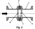
- the device as illustrated for example, in Figs. 1A-2 and 4A-C , is contemplated to be placed in series with a medium/cell suspension outflow from a cell culture system, whereby the cell suspension may be passed via a conduit (1) of the device and therefore through a turbulence chamber (2).
- the cell suspension will enter into the flow-through dispersion device via an upstream inlet (3) of the conduit (1) and will exit from the device via a downstream outlet (4) of the conduit (1).
- the internal walls (10, 11) of the inlet (3) and outlet (4) of the conduit (1) may have cross section diameters smaller than, equal to or larger than that of the turbulence chamber (2).
- a cross section of a conduit inlet (3) or outlet (4) is by definition a section perpendicular to the direction of a liquid flow passing through the conduit (1).
- conduit (1) there is no restriction as to a particular form of the conduit (1), in particular in the forms of its cross-section.
- the cross-section of the conduit (1) may be, but is not limited to, a circular, ovoid, square or rectangular cross-section.
- the cross-section of the turbulence chamber (2) is advantageously configured, but not necessarily, to the form of the conduit (1).
- the turbulence chamber (2) of the flow-through dispersion device is defined by the opposing internal walls of two obstacles ( 14, 15 respectively), an upstream inlet obstacle (14) closest to the upstream inlet (3) of the conduit (1), and a downstream outlet obstacle (15) closest to the downstream outlet (4) of the conduit (1), and an inner wall (16) defining the distance separating the obstacles from each other.
- Each obstacle (14, 15) therefore, is located within the conduit (1) and orientated most advantageously perpendicular to the central axis of the flow-through dispersion device so as to impede the flow of cell culture fluid passing through the conduit (1). It is further contemplated that there may be more than two obstacles as shown, for example, in Figs.
- each adjacent pair of obstacles and the inner wall of the conduit each defines a turbulence chamber (2), thereby forming a plurality of chambers (2) arranged in series.
- the outlet obstacle (15) of a first turbulence chamber (2') may function also as the inlet obstacle for a second turbulence chamber (2") serially located immediately downstream of the first chamber (2') as shown in Figs. 4A-4C .
- Each upstream inlet obstacle (14) and a downstream outlet obstacle (15) is perforated with at least one traversing hole (16) allowing communication of the inlet (3) and outlet (4) of the conduit with the turbulence chamber (2).
- a traversing hole is defined by an equivalent diameter of a cylindrically-shaped hole having the same section. This equivalent diameter advantageously is at least 25 times greater, more advantageously 50 times greater, and more advantageously at least hundredfold greater than the diameter of an individual live cell of the culture.
- the cross-sectional area or combined cross-sectional areas of the traversing hole(s) (16) of an obstacle (14, 15) impedes fluid flow through the conduit (1) from between about 50% to about 99.9%.
- the fluid flow obstruction expressed in percentage, is calculated by the following formula (X-Y)/X, wherein X is the cross-sectional area of the conduit and Y is the sum of areas of the hole or plurality of holes of the obstacle.
- the fluid flow obstruction created by an obstacle is from about 50% to about 99.9%. More advantageously, the fluid flow obstruction created by the obstacle may be from about 60% to about 99.9%, more advantageously from about 70% to about 99.9%, more advantageously yet from about 80% to about 99.9%, and most advantageously from about 90% to about 99.9%.
- No traversing hole (16) of an upstream inlet obstacle (14) may be concentric with any hole (16) of the immediately succeeding downstream outlet obstacle (15), i.e. the longitudinal axis of one hole (16) is not coincident with the longitudinal axis of any other hole of the flow-through dispersion device as shown, for example, in Figs, 3A and 3B .
- the configurations of the upstream inlet obstacle (14) and downstream outlet obstacles (15) and the traversing holes (16) therein, are not limited as to the thickness of the obstacles which also may be, but not limited to, a circular, ovoid, square or rectangular cross-section, nor in the number, sizes and forms of the traversing holes (16).
- the traversing holes (16) may also be non-uniform and may have a variety of cross-sections.
- the device may, for example, have all its obstacles each with one hole.
- the device may have all its obstacles (14, 15) with several holes (16) having all the same size and form.
- the device may have obstacles (14, 15) with several holes (16) having different sizes and forms, or each obstacle (14, 15) has the same type of holes but the size and form of holes differ from one obstacle to the other.
- the flow-through dispersion device of the invention may comprise at least two separable portions, an inlet portion (3) and an outlet portion (4) with, as shown for example in Fig 1A , an optional spacer seal (5) to prevent leakage of fluid from the turbulence chamber (2) and which contributes to the separation between the two opposing obstacles (14, 15).
- the obstacles (14, 15) may be separate and removable from the conduit (1) after separation of the two portions (3, 4).
- the device is a single integrated unit, as illustrated, for example, in Fig. 4C .
- the flow-through dispersion device may further comprise a securing means (6), as schematically illustrated in Figs 1B and 4B for example, for ensuring that the two portions (3, 4) of the device and optionally the spacer seal (5) are operably connected with no leakage of fluids passing through the device.
- the securing means may be, but is not limited to, a clamp, opposing springs, an elastic seal and the like.
- One aspect of the invention encompasses a flow-through dispersion device for the dispersion of aggregates, the device comprising an upstream inlet (3) at one extremity of a conduit (1), a first or upstream inlet obstacle (14) within the conduit (1), this upstream inlet obstacle (14) having at least one traversing hole (16) that provides from about 50% to about 99.9% obstruction of the internal cross-section of the conduit (1), a second or downstream outlet obstacle (15) inside the conduit (1), this downstream outlet obstacle (15) having at least one traversing hole (16) providing from about 50% to about 99.9% obstruction of the internal cross-section of the conduit (1), wherein the longitudinal axis of any hole (16) perforating any obstacle (14, 15) does not align with the longitudinal axis of any hole of a preceding or succeeding obstacle, and wherein the distance between two successive obstacles is from about 0.1 to about 10 times the diameter of the smallest hole of either of two successive obstacles, and a downstream outlet (4) at the opposing extremity of the conduit (1).
- the first, or upstream inlet obstacle (14) comprises a plurality of traversing holes (16), wherein the cross-section configurations of the holes (16) may be selected from circular, concentric and rectilinear, and wherein the longitudinal axis of each hole (16) is parallel to the longitudinal axis of the conduit, thereby creating from about 50% to about 99.9% obstruction of the section of the conduit (1), and wherein the holes (16) may be identical or different from one another.
- the second, or downstream outlet obstacle (15) comprises a plurality of traversing holes (16), wherein the cross-section configurations of the holes (16) are selected from circular, concentric and rectilinear, and wherein the longitudinal axis of each hole is parallel to the longitudinal axis of the conduit (1), thereby creating from about 50% to about 99.9% obstruction of the section of the conduit (1), and wherein the holes (16) may be identical or different from one another.
- the first, or upstream inlet obstacle (14), as shown in Fig 3A comprises three traversing holes (16), wherein the cross-section configurations of the holes (16) may be selected from circular, concentric and rectilinear, and wherein the longitudinal axis of each hole is parallel to the longitudinal axis of the conduit, thereby creating from about 50% to about 99.9% obstruction of the section of the conduit, and wherein the holes (16) may be identical or different from one another, and the second, or downstream outlet obstacle (15) as shown in Fig.
- 3B comprises a three traversing holes (16), wherein the cross-section configurations of the holes are selected from circular, concentric and rectilinear, and wherein the longitudinal axis of each hole is parallel to the longitudinal axis of the conduit, thereby creating from about 50% to about 99.9% obstruction of the section of the conduit, and wherein the holes may be identical or different from one another and wherein the longitudinal axis of any hole (16) through the first obstacle (14) does not align with the longitudinal axis of any hole of the second obstacle (15).
- the upstream inlet obstacle (14) and downstream outlet obstacles (15) are advantageously, but not necessarily, perpendicular to the direction of the flow passing through the conduit (1).
- the holes traversing the inlet obstacle (14) and downstream outlet obstacle (15) may be cylindrically-shaped, concentric, or rectilinear, wherein the longitudinal axes of the holes are parallel to the longitudinal axis of the conduit.
- first (3) and second (4) portions each comprises a conduit (1) having a longitudinal lumen (7) and an obstacle (14,15) located therein and perpendicular to the longitudinal axis of the lumen (7) of the conduit (1) and a spacer seal (5), whereby the first (3) and second (4) portions may be juxtaposed and secured together such that a turbulence chamber is defined by the two obstacles (14, 15), and at least the inner wall (17) of the spacer seal (5).
- a turbulence chamber is defined by the two obstacles (14, 15), and at least the inner wall (17) of the spacer seal (5).
- Another aspect of the present invention encompasses a method of using the flow-through dispersion device according to the present invention.
- the present invention encompasses the use of the device according to the present invention to disperse aggregates, especially culture suspensions containing cell aggregates.
- the method for dispersion of aggregates according to the invention comprises the steps of (1) flowing a suspension containing cell aggregates through at least one flow-through dispersion device according to the invention, (2) disrupting the aggregates, (3) optionally repeating step (1) by repassaging the cell suspension through the device, and (4) harvesting the suspension containing individual cells.
- a method for dispersion of aggregates comprises the steps of (1) flowing of a suspension containing cell aggregates through at least one dispersion device, said device comprising an upstream inlet at one extremity of a cylindrical-shaped conduit; a first obstacle inside the conduit and perpendicular to the direction of the flow circulating through this conduit, this first obstacle having three traversing holes, parallel to the longitudinal axis of the conduit, and wherein the combined cross-sectional area of the holes is about 2% of the total cross-sectional area of the conduit; a second downstream obstacle inside the outlet conduit and perpendicular to the direction of the flow circulating through this conduit, this second obstacle having 3 traversing holes parallel to the longitudinal axis of the conduit, and wherein the combined cross-sectional area of the holes is about 2% of the total cross-sectional area of the conduit, and wherein the holes of the downstream outlet obstacle are positioned relative to the holes of the upstream obstacle so as not to have the same longitudinal alignment that any hole of the upstream obstacle, and wherein the distance between these two obstacles is about twice the
- a plurality of the flow-through dispersion devices of the invention may be used for dispersion of aggregates, the devices being placed in serial and the suspension containing cell aggregates flowing through all the devices placed in serial.
- two to seven devices can be placed in serial or a single device with multiple successive turbulence chambers may be employed.
- a dispersion device may be used in a recirculation mode.
- the cell suspension container is connected to the upstream inlet of the conduit and to the downstream outlet of the conduit.
- the cell suspension is successively and continuously flowing through the upstream inlet of the conduit, the turbulence chamber, the downstream outlet of the conduit and is recycled inside the cell suspension container.
- Another aspect of the invention is a method of cell culture, comprising the steps of (1) introducing cells to be cultured into a culture medium and culturing the cells, (2) displacing or suspending the cultured cells in a medium, wherein the suspension comprises cell aggregates, (3) passing the cell suspension containing cell aggregates through one flow-through a dispersion device according to the invention or through a serial arrangement of such devices, thereby disrupting the cell aggregates and releasing individual cells therefrom, (4) optionally repeating steps (1) to (3) are repeated as many times as necessary, and (5) reintroducing at least a portion of the disrupted cell suspension from step (3) into the culture batch and reculturing the cells.
- the culture medium may comprise micro-carriers.
- the flow-through dispersion device of the invention may be used in a continuous loop, whereby the culture medium is circulated through the device to disrupt cell clusters as they form.
- the devices and methods of the present invention allow in a continuous flow-through mode to subject a cell suspension containing cell aggregates to fluid turbulences to disperse and disrupt the aggregates thereby releasing the individual live cells.
- the device is a passive device and does not contain any moving part, like rotor or piston, thereby allowing for easy cleaning and reducing the likelihood of damage to the cells.
- Turbulence forces are applied to the aggregates during the acceleration of the fluid through the obstacle hole(s) traversing the obstacles and during the reorientation of the flux between two successive obstacles.
- the distance between two successive obstacles and the fact that the hole(s) of the first obstacle is not placed in the same longitudinal alignment as any hole of the next obstacle creates turbulences.
- aggregates, and more specifically macroscopic aggregates are susceptible to collide with the obstacles, which could also favor aggregate dispersion.
- the continuous flow-through mode of the present invention compared to a batch mode (i.e. pipetting method) has the advantage of avoiding dead spaces inside the turbulence system. All the cells pass through the turbulence chamber for an efficient dispersion of aggregates, and consequently the continuous flow-through mode of the present invention results in improved dispersion of the aggregates.
- the device of the present invention also allows to reduce the open phases by operating in continuous flow-through mode, which results in a decrease of the risk of contamination.
- the continuous flow-through mode of the present invention limits the aggregates to a unique and quick passage inside the device. Due to the flow, there is no possibility for the aggregate to pass twice through the holes of the obstacles, and consequently cells are less stressed and the cell viability is better.
- the processing flow-rate will be adjusted to the device geometry and to the cell type since cell shear sensitivity is related to the cell type, the culture age and history and maintenance conditions. Virus infection usually leads to an increase of the shear sensitivity.
- the density of a cell suspension can be easily and quickly established as well as determining the presence or not of cells aggregates.
- the hemocytometer can also be used to distinguish live cells from dead cells in order to determine the percentage of viable cells.
- vital stain indicators which stain only nonvital tissues and cells. Cells are permeable to such indicators but live cells are able to exclude them. Dead and dying cells cannot exclude the indicators and therefore display staining.
- the most commonly vital stain indicator is trypan blue ( Hoffmeister E.R., Stain Technol., 28(6): 309-310 (1953 ); Boedijn K.B., Stain Technol., 31(3): 115-116 (1956 ); Allison D.C.
- the average velocity of the suspension containing cell aggregates through the holes of the device according to the present invention should be between about 0.1 and about 100 m/s, preferably between about 0.1 and about 20 m/s and more preferably between about 0.5 and about 5 m/s.
- Methods of cell culture may comprise the steps of (1) introducing cells to be cultured into a culture batch filed with a culture medium and culturing the cells, (2) flowing of the suspension obtained in step (1) and containing cell aggregates through at least one device according to the invention and disrupting the aggregates, (3) reintroducing the suspension obtained in step (2) and containing individual cells into the culture batch, (4) optionally repeating steps (1) to (3), and (5) harvesting the suspension containing individual cells obtained after step (2) or step (4).
- the use of the dispersion device according to the invention may allow a reduction in the time needed for dispersion and/or to reduce the added quantity of chelating agents or proteolytic enzymes, notably trypsin.
- the dispersion device according to the invention could be used continuously in recirculation or in a continuous flow-through mode.
- the use of the dispersion device according to the invention during the chemical or proteolytic dispersion step results in a better release of the cells from the micro-carriers.
- This use increases the yield of the cells harvested after the discarding of micro-carriers by clarification.
- At least one dispersion device can be used continuously in recirculation during cell culture. Depending on the cell type, the culture history and maintenance conditions, cell aggregates can occur during the culture. It would be beneficial to disperse these aggregates into individual cells (i.e. to increase of the contact surface between cells and the culture medium, to avoid apoptosis phenomena). In this particular situation, the dispersion device of the present invention can be used in recirculation because it allows to operate in closed circuit.
- the devices and methods of the invention are suitable for use with a variety of cells including, but not limited to, prokaryotic cells such as bacteria and particularly Escherichia coli (E. coli), and eukaryotic cells such as, but not limited to, yeast, plant cells, and animal cells including insect cells or mammalian cells.
- the biological compounds of interest are RNAs, DNAs, viruses or phages, proteins.
- Animal cells particularly suitable for use of the present invention include cells of human, primate, rodent, porcine, bovine, canine, feline, ovine, avian origin and derivatives thereof.
- animal cells include epithelial cells, which may be primary cells derived from an embryonic tissue sample or adult tissue sample, such as keratinocytes, cervical epithelial cells, bronchial epithelial cells, tracheal epithelial cells, kidney epithelial cells or retinal epithelial cells, or transformed cells or established cell lines (e.g., 293 human embryonic kidney cells, HeLa cervical epithelial cells or derivatives thereof (e.g., HeLaS3), PER-C6 human retinal cells and HCAT human keratinocytes), or derivatives thereof.
- the cells may be normal cells, or may be genetically altered.
- animal cells such as CHO cells, COS cells, VERO cells, BHK cells (including BHK-21 cells), CLDK cells, CRFK cells, PK15 cells, MDBK cells, MDCK cells, TCF cells, TDF cells, CEF cells and derivatives thereof, are also suitable for application of the present invention.
- the cells are harvested by any means known by the persons skilled in the art, including settling or centrifugation.
- the cells may be harvested and concentrated by centrifugation, in particular by bucket centrifugation. Further the cells may be stored in a refrigerated form or in a frozen form.
- Marek disease virus MDV
- Infected chicken embryo cells of all the rolling bottles were dissociated by trypsination after attaining 50 to 70% CPE (cytopathic effect), then harvested by centrifugation at 500g during 12 minutes.
- a first method the cell suspension from 406 rolling bottles was homogenized by manual pipetting with a 50 ml pipette. The resulting suspension was extemporaneously filtered on a 800 ⁇ m Nylon bag, adjusted in volume with some freezing media then analyzed.
- the cell suspension equivalent of 48 rolling bottles was processed 8 times consecutively through a flow-through dispersion device according to the invention and as illustrated in Fig. 1 .
- the dispersion device constituted two portions, each one having a conduit (cylindrically-shaped, 34 mm of length and 36.5 mm internal diameter) ending with an obstacle (a plate perpendicular to the conduit axis) (see Fig. 1 ).
- Each plate included three cylindrically-shaped rectilinear holes each having a diameter of 3 mm, and equidistant and parallel to the axis of the conduit.
- the distance between one hole and the conduit axis was 31 mm (see Fig. 2A ). With the other portion, this distance was equal to 10 mm (see Fig. 2B model).
- the two conduits were joined by opposing the ends of the conduit having the obstacle therein to a distance between the two obstacles of about 6 mm).
- the cell suspension recovered after centrifugation was injected through the dispersion device with a flow rate of about 150 1/h by using a peristaltic pump. Samples were taken before and after each passage through the device and analysed after a 800 ⁇ m nylon filtration. The injection through the dispersion device and sampling and analysis were reproduced 7 times.
- Table 1 Sampling Individual cell numeration (cells / ml) Viability (%) Visual observations Virus titre (Log10pfu/ml) 1 st passage Before filtration 3.0E07 80 Very thick Many large clumps 6.99 1 st passage After filtration 4.4E07 84 Many clumps Many residues on the filter 7.05 2 nd passage After filtration 3.8E07 77 Many clumps Many residues on the filter 7.16 3 rd passage After filtration 4.3E07 75 Some clumps Less residues on the filter 6.83 4 th passage After filtration 5.2E07 71 Less clumpy few residues on the filter 7.14 5 th passage After filtration 5.8E07 70 Very few clumps few residues on the filter 6.95 6 th passage After filtration 4.9E07 68 Very few clumps few residues on the filter 7.17 7 th passage After filtration 4.8E07 66 Very few clumps few residues on the filter 7.1 8 th passage Before filtration
- the supernatant was removed and freezing media was added to the centrifugation bucket containing the pellet.
- the bucket was swirled by hand to obtain a coarse cell suspension, but which still contained many aggregates visible to the naked eye.
- the cell suspension was stirred during 10 minutes and divided equally into six containers.
- One container was processed as a standard without cell splitting.
- the cell suspension was directly filtered on a cheese-cloth.
- the filtrate was furthermore diluted with freezing media before filling.
- the five remaining containers were split in a continuous way before cheese-cloth filtration and freezing media dilution.
- the number of dispersion devices (dispersion devices as described in Example 1) and the processing flow-rate were changed from one serial to the other.
- the final products were analyzed for cell numeration expressed in number of cells per rolling bottles for trial comparison. Results are presented in Table 2.
- Table 2 Splitting conditions Number of roller bottles processed Individual cell numeration (millions of cells / rolling bottle) Standard 388 423 3 dispersion devices in series 50 l/h 388 466 7 dispersion devices in series 50 l/h 388 452 5 dispersion devices in series 150 l/h 388 466 3 dispersion devices in series 250 l/h 367 431 7 dispersion devices in series 250 l/h 388 436
Landscapes
- Health & Medical Sciences (AREA)
- Life Sciences & Earth Sciences (AREA)
- Engineering & Computer Science (AREA)
- Organic Chemistry (AREA)
- Bioinformatics & Cheminformatics (AREA)
- Wood Science & Technology (AREA)
- Zoology (AREA)
- Chemical & Material Sciences (AREA)
- Biomedical Technology (AREA)
- Biotechnology (AREA)
- Genetics & Genomics (AREA)
- General Engineering & Computer Science (AREA)
- Biochemistry (AREA)
- General Health & Medical Sciences (AREA)
- Microbiology (AREA)
- Sustainable Development (AREA)
- Cell Biology (AREA)
- Developmental Biology & Embryology (AREA)
- Gynecology & Obstetrics (AREA)
- Reproductive Health (AREA)
- Molecular Biology (AREA)
- Apparatus Associated With Microorganisms And Enzymes (AREA)
- Micro-Organisms Or Cultivation Processes Thereof (AREA)
Claims (15)
- Dispositif de dispersion à écoulement traversant pour la dispersion d'agrégats, le dispositif comprenant une entrée d'admission à une extrémité d'un conduit, au moins deux obstacles ayant des surfaces opposées, lesdits obstacles étant un premier obstacle d'admission ou en amont disposé dans le conduit, ledit obstacle d'admission en amont étant perforé par au moins un trou traversant et obstruant d'environ 50 % à environ 99,9 % de la section transversale interne du conduit, un second obstacle de refoulement ou en aval disposé dans le conduit et un obstacle de refoulement en aval étant perforé par au moins un trou traversant et obstruant d'environ 50 % à environ 99,9 % de la section transversale interne du conduit, dans lequel l'axe longitudinal d'un quelconque trou traversant de l'un ou l'autre obstacle ne s'aligne pas avec l'axe longitudinal d'un quelconque autre trou d'un obstacle précédent ou suivant, une chambre de turbulence définie par les surfaces opposées des premier et second obstacles et la paroi interne du conduit entre lesdits obstacles, et dans lequel la distance entre deux obstacles successifs est d'environ 0,1 à environ 10 fois le diamètre du trou le plus petit de l'un ou l'autre de deux obstacles successifs, et un refoulement d'aval à l'extrémité opposée du conduit ; et dans lequel l'admission du conduit du dispositif et l'obstacle d'admission en amont forment une première partie du dispositif, et le refoulement du conduit du dispositif et l'obstacle de refoulement d'aval forment une seconde partie du dispositif et dans lequel les première et seconde parties sont séparables, dans lequel le dispositif comprend en outre un joint d'écartement ; dans lequel en outre le conduit dans chacune des première et deuxième parties comprend une lumière longitudinale, moyennant quoi les première et seconde parties peuvent être juxtaposées et fixées ensemble de sorte qu'une chambre de turbulence soit définie par les au moins deux obstacles et au moins une paroi interne du joint d'écartement.
- Dispositif selon la revendication 1, dans lequel les obstacles d'admission et de refoulement sont démontables du dispositif ou de parties de celui-ci.
- Dispositif selon la revendication 1, dans lequel l'obstacle d'admission en amont et l'obstacle de refoulement en aval sont perpendiculaires à la direction de l'écoulement du fluide à travers le conduit.
- Dispositif selon la revendication 1, dans lequel un trou ou des trous traversant l'obstacle d'admission en amont et l'obstacle de refoulement en aval sont parallèles à l'axe longitudinal du conduit.
- Dispositif selon la revendication 1, comprenant en outre un moyen de fixation pour maintenir l'intégrité du dispositif.
- Dispositif selon la revendication 1, dans lequel le conduit d'admission, les obstacles d'admission et de refoulement, la chambre de turbulence et le conduit de refoulement sont formés en une seule unité.
- Dispositif selon la revendication 1, comprenant en outre au moins un obstacle supplémentaire définissant ainsi au moins deux chambres de turbulence.
- Dispositif selon la revendication 1, dans lequel les obstacles d'admission en amont et de refoulement en aval comprennent chacun trois trous traversants, dans lequel les configurations de section transversale des trous sont sélectionnées parmi circulaires, ovoïdes, concentriques et rectilignes, créant ainsi chacune d'environ 50 % à environ 99,9 % d'obstruction de la section transversale du conduit, et dans lequel les trous peuvent être identiques ou différents les uns des autres, et dans lequel l'axe longitudinal d'un quelconque trou à travers le premier obstacle n'est pas aligné avec l'axe longitudinal d'un quelconque trou du second obstacle.
- Dispositif selon la revendication 1 comprenant une admission en amont à une extrémité d'un conduit, au moins deux obstacles ayant des surfaces opposées, lesdits obstacles étant un premier obstacle d'admission ou en amont dans le conduit, l'obstacle d'admission en amont étant perforé par au moins un trou traversant et obstruant d'environ 50 % à environ 99,9 % de la section transversale interne du conduit, un second obstacle de refoulement ou en aval à l'intérieur du conduit, et l'obstacle de refoulement en aval étant perforé par au moins un trou traversant et obstruant d'environ 50 % à environ 99,9 % de la section transversale interne du conduit, dans lequel l'obstacle d'admission en amont et l'obstacle de refoulement en aval sont perpendiculaires à la direction d'écoulement du fluide à travers le conduit et les trous traversant l'obstacle d'admission et l'obstacle de refoulement en aval sont parallèles à l'axe longitudinal du conduit, et dans lequel l'axe longitudinal d'un quelconque trou traversant de l'un ou l'autre obstacle n'est pas aligné avec l'axe longitudinal d'un quelconque autre trou d'un obstacle précédent ou suivant, et une chambre de turbulence définie par les surfaces opposées des premier et second obstacles et la paroi interne du conduit entre lesdits obstacles, et dans lequel la distance entre deux obstacles successifs est d'environ 0,1 à environ 10 fois le diamètre du trou le plus petit de l'un ou l'autre de deux obstacles successifs, et un refoulement en aval à l'extrémité opposée du conduit, dans lequel l'admission du conduit du dispositif et l'obstacle d'admission en amont forment une première partie du dispositif, et le refoulement du dispositif et l'obstacle de refoulement en aval forment une seconde partie du dispositif et dans lequel les première et seconde parties sont séparables, et un joint d'écartement, dans lequel la chambre de turbulence est définie par les surfaces opposées des deux obstacles et la paroi interne du dispositif entre les obstacles.
- Dispositif selon la revendication 9, dans lequel le conduit est de forme cylindrique, l'obstacle d'admission a 3 trous créant environ 98 % d'obstruction de la section transversale du conduit ; l'obstacle de refoulement a 3 trous créant environ 98 % d'obstruction de la section transversale du conduit, dans lequel les trous de l'obstacle de refoulement n'ont pas le même alignement longitudinal qu'un quelconque trou de l'obstacle d'admission, et dans lequel la distance séparant ces deux obstacles est d'environ deux fois le diamètre d'un quelconque trou.
- Procédé de dispersion d'agrégats, comprenant les étapes consistant à :(1) faire passer une suspension cellulaire contenant des agrégats cellulaires à travers au moins un dispositif selon la revendication 1 ;(2) désunir les agrégats cellulaires dans la suspension cellulaire,(3) répéter facultativement l'étape (1) en faisant repasser la suspension à travers le dispositif ; et(4) recueillir la suspension cellulaire contenant les agrégats cellulaires désunis.
- Procédé selon la revendication 11, dans lequel la suspension cellulaire est amenée à passer à travers un agencement en série d'une pluralité de dispositifs selon la revendication 1.
- Procédé de culture de cellules, comprenant les étapes consistant à :(1) introduire des cellules à cultiver dans un milieu de culture et cultiver les cellules ;(2) déplacer ou suspendre les cellules cultivées dans un milieu, dans lequel la suspension comprend des agrégats cellulaires ;(3) faire passer la suspension cellulaire contenant des agrégats cellulaires à travers un dispositif de dispersion à écoulement traversant selon la revendication 1 ou à travers un agencement en série de tels dispositifs, désunissant ainsi les agrégats cellulaires et libérant les cellules individuelles de ceux-ci ;(4) répéter facultativement les étapes (1) à (3) autant de fois que nécessaire, et(5) réintroduire au moins une partie de la suspension de cellules désunies de l'étape (3) dans le lot de culture et cultiver de nouveau les cellules.
- Procédé selon la revendication 13, dans lequel le milieu de culture comprend des microsupports.
- Procédé selon la revendication 13, dans lequel l'étape (3) est continue pendant la période de culture.
Priority Applications (3)
| Application Number | Priority Date | Filing Date | Title |
|---|---|---|---|
| EP18181984.8A EP3428267B1 (fr) | 2006-10-11 | 2007-10-10 | Dispositifs de dispersion pour agrégats |
| SI200732065T SI2076157T1 (sl) | 2006-10-11 | 2007-10-10 | Disperzijske naprave za agregate |
| PL07871147T PL2076157T3 (pl) | 2006-10-11 | 2007-10-10 | Urządzenia dyspersyjne do agregatów |
Applications Claiming Priority (2)
| Application Number | Priority Date | Filing Date | Title |
|---|---|---|---|
| US85103706P | 2006-10-11 | 2006-10-11 | |
| PCT/US2007/080958 WO2008067044A2 (fr) | 2006-10-11 | 2007-10-10 | Dispositifs de dispersion pour agrégats |
Related Child Applications (1)
| Application Number | Title | Priority Date | Filing Date |
|---|---|---|---|
| EP18181984.8A Division EP3428267B1 (fr) | 2006-10-11 | 2007-10-10 | Dispositifs de dispersion pour agrégats |
Publications (3)
| Publication Number | Publication Date |
|---|---|
| EP2076157A2 EP2076157A2 (fr) | 2009-07-08 |
| EP2076157A4 EP2076157A4 (fr) | 2012-07-04 |
| EP2076157B1 true EP2076157B1 (fr) | 2018-08-01 |
Family
ID=39468568
Family Applications (2)
| Application Number | Title | Priority Date | Filing Date |
|---|---|---|---|
| EP07871147.0A Active EP2076157B1 (fr) | 2006-10-11 | 2007-10-10 | Dispositifs de dispersion pour agrégats |
| EP18181984.8A Active EP3428267B1 (fr) | 2006-10-11 | 2007-10-10 | Dispositifs de dispersion pour agrégats |
Family Applications After (1)
| Application Number | Title | Priority Date | Filing Date |
|---|---|---|---|
| EP18181984.8A Active EP3428267B1 (fr) | 2006-10-11 | 2007-10-10 | Dispositifs de dispersion pour agrégats |
Country Status (12)
| Country | Link |
|---|---|
| US (1) | US7658341B2 (fr) |
| EP (2) | EP2076157B1 (fr) |
| CY (1) | CY1121073T1 (fr) |
| DK (1) | DK2076157T3 (fr) |
| ES (1) | ES2688284T3 (fr) |
| HU (1) | HUE040347T2 (fr) |
| LT (1) | LT2076157T (fr) |
| PL (1) | PL2076157T3 (fr) |
| PT (1) | PT2076157T (fr) |
| SI (1) | SI2076157T1 (fr) |
| TR (1) | TR201816129T4 (fr) |
| WO (1) | WO2008067044A2 (fr) |
Families Citing this family (9)
| Publication number | Priority date | Publication date | Assignee | Title |
|---|---|---|---|---|
| US9631174B2 (en) | 2008-04-10 | 2017-04-25 | Georgia Tech Research Corporation | Methods and devices for dispersing somatic plant embryos |
| BRPI0910328B1 (pt) * | 2008-04-10 | 2018-04-24 | Georgia Tech Research Corporation | Métodos e dispositivos para dispersar embriões somáticos de planta |
| US8927287B2 (en) * | 2009-10-09 | 2015-01-06 | Georgia Tech Research Corporation | Method for dispersion of assemblies of biological material |
| US10004189B2 (en) | 2009-10-09 | 2018-06-26 | Georgia Tech Research Corporation | Separator device, deposition device and system for handling of somatic plant embryos |
| ES2546411T3 (es) | 2009-10-09 | 2015-09-23 | Georgia Tech Research Corporation | Dispositivo separador, dispositivo de deposición y sistema para manipular embriones vegetales somáticos |
| US20180080002A1 (en) * | 2014-07-22 | 2018-03-22 | Hitachi High-Technologies Corporation | Cell dispersion device, and automatic subculture system using same |
| CN104195038B (zh) * | 2014-09-11 | 2016-06-15 | 广州聚能纳米生物科技股份有限公司 | 同轴线双高压缸均质一体化装置 |
| DE102016202139A1 (de) | 2016-02-12 | 2017-08-17 | Hamilton Bonaduz Ag | Zellvereinzelungsvorrichtung und Verwendung einer Strömungsformation zur Zellvereinzelungsvorrichtung |
| CN106976160A (zh) * | 2017-02-24 | 2017-07-25 | 南通弘亚机械制造有限公司 | 具有较高均匀性的水泥粉体气力均化装置 |
Family Cites Families (12)
| Publication number | Priority date | Publication date | Assignee | Title |
|---|---|---|---|---|
| NL48062C (fr) * | 1938-03-11 | 1939-10-16 | ||
| BE623894A (fr) | 1961-10-20 | |||
| FI80617C (fi) * | 1986-05-09 | 1990-07-10 | Finnpulva Ab Oy | Foerfarande och anordning foer foerbaettrande av malningsresultatet i en tryckammarkvarn. |
| FI84032C (fi) * | 1988-11-28 | 1991-10-10 | Finnpulva Ab Oy | Foerfarande och anlaeggning foer klassificering av synnerligen finfoerdelat material. |
| US5356814A (en) * | 1992-09-29 | 1994-10-18 | Hoffmann-La Roche Inc. | Disaggregation device for cytological specimens |
| US5598979A (en) * | 1995-04-20 | 1997-02-04 | Vortec, Inc. | Closed loop gradient force comminuting and dehydrating system |
| US5968018A (en) * | 1996-10-30 | 1999-10-19 | Cohesion Corporation | Cell separation device and in-line orifice mixer system |
| US6786437B2 (en) * | 1998-06-19 | 2004-09-07 | Harris J. Ribardi | Closed loop cyclonic mill, and method and apparatus for drying and fiberizing material |
| US6138931A (en) | 1999-07-27 | 2000-10-31 | Xerox Corporation | Apparatus and method for grinding particulate material |
| US6623959B2 (en) * | 2001-06-13 | 2003-09-23 | Ethicon, Inc. | Devices and methods for cell harvesting |
| US6739531B2 (en) | 2001-10-04 | 2004-05-25 | Cepheid | Apparatus and method for rapid disruption of cells or viruses |
| TWM249953U (en) * | 2003-03-19 | 2004-11-11 | Yeu Ming Tai Chemical Ind Co L | Processing device for nano-material |
-
2007
- 2007-10-10 EP EP07871147.0A patent/EP2076157B1/fr active Active
- 2007-10-10 DK DK07871147.0T patent/DK2076157T3/en active
- 2007-10-10 EP EP18181984.8A patent/EP3428267B1/fr active Active
- 2007-10-10 ES ES07871147.0T patent/ES2688284T3/es active Active
- 2007-10-10 WO PCT/US2007/080958 patent/WO2008067044A2/fr not_active Ceased
- 2007-10-10 PL PL07871147T patent/PL2076157T3/pl unknown
- 2007-10-10 US US11/870,059 patent/US7658341B2/en active Active
- 2007-10-10 TR TR2018/16129T patent/TR201816129T4/tr unknown
- 2007-10-10 PT PT07871147T patent/PT2076157T/pt unknown
- 2007-10-10 HU HUE07871147A patent/HUE040347T2/hu unknown
- 2007-10-10 LT LTEP07871147.0T patent/LT2076157T/lt unknown
- 2007-10-10 SI SI200732065T patent/SI2076157T1/sl unknown
-
2018
- 2018-09-25 CY CY181100989T patent/CY1121073T1/el unknown
Non-Patent Citations (1)
| Title |
|---|
| None * |
Also Published As
| Publication number | Publication date |
|---|---|
| CY1121073T1 (el) | 2019-12-11 |
| EP3428267B1 (fr) | 2023-11-29 |
| EP2076157A2 (fr) | 2009-07-08 |
| EP3428267A1 (fr) | 2019-01-16 |
| US20080108137A1 (en) | 2008-05-08 |
| US7658341B2 (en) | 2010-02-09 |
| DK2076157T3 (en) | 2018-11-26 |
| TR201816129T4 (tr) | 2018-11-21 |
| LT2076157T (lt) | 2018-11-12 |
| ES2688284T3 (es) | 2018-10-31 |
| SI2076157T1 (sl) | 2018-12-31 |
| WO2008067044A3 (fr) | 2008-12-04 |
| PT2076157T (pt) | 2018-11-16 |
| WO2008067044A2 (fr) | 2008-06-05 |
| HUE040347T2 (hu) | 2019-03-28 |
| EP2076157A4 (fr) | 2012-07-04 |
| PL2076157T3 (pl) | 2018-12-31 |
Similar Documents
| Publication | Publication Date | Title |
|---|---|---|
| EP3428267B1 (fr) | Dispositifs de dispersion pour agrégats | |
| JP7501365B2 (ja) | 分離デバイスおよびそれを用いて分離対象物を分離する方法 | |
| JP6758659B2 (ja) | 揺動プラットフォームバイオリアクターを用いた多能性幹細胞の増殖及び継代 | |
| Emery et al. | Purification of oligodendrocyte lineage cells from mouse cortices by immunopanning | |
| AU2011281982B2 (en) | Method for harvesting expression products | |
| KR102022952B1 (ko) | 백시니아 바이러스의 생산을 위한 방법 및 조성물 | |
| EP1427817B1 (fr) | Multiplication de virus dans une culture cellulaire | |
| US20150064768A1 (en) | Systems and Methods for Virus Propagation in Cell Cultures for Vaccine Manufacture | |
| AU2013246084B2 (en) | Alternating ionic magnetic resonance (AIMR) multiple-chambered culture apparatus and methods of use | |
| Nema et al. | An animal cell culture: Advance technology for modern research | |
| CN108474140A (zh) | 大规模细胞生产系统 | |
| CN108779424A (zh) | 使用搅拌槽生物反应器的多能干细胞扩增和传代 | |
| DE69835813T2 (de) | Verfahren zur kultivierung von zellen und zur vermehrung von viren | |
| HK1133165B (en) | Dispersion devices for aggregates | |
| HK1133165A (en) | Dispersion devices for aggregates | |
| RU2488631C1 (ru) | ЛИНИЯ КЛЕТОК ПОЧКИ ТЕЛЕНКА Bos taurus RBT (Rene Bos Taurus) ДЛЯ РЕПРОДУКЦИИ ВИРУСОВ ЖИВОТНЫХ | |
| CN114736847B (zh) | 一种快速获取大鲵原代性腺细胞的方法 | |
| Bak et al. | Long-term human organotypic brain slice cultures: a detailed protocol to provide a comprehensive framework for single-neuron and neuronal network investigations | |
| CN115948334A (zh) | 一株鳜鱼脑细胞克隆细胞株及其应用 | |
| Roberts et al. | Synthesis of Maus-Elberfeld viral RNA in ascites tumor cells | |
| CN118956732B (zh) | 一种鸭眼角膜上皮细胞悬浮细胞株及其构建方法与应用 | |
| CN120665803A (zh) | 黄芪甲苷在调节孤雌激活胚胎发育中的应用 | |
| CN120665802A (zh) | 番茄红素在绵羊卵母细胞体外培养中的应用 | |
| Tapia Delgado | Continuous upstream processing for cell culture-derived virus production | |
| Tapia | Continuous upstream processing for cell culture-derived virus production |
Legal Events
| Date | Code | Title | Description |
|---|---|---|---|
| PUAI | Public reference made under article 153(3) epc to a published international application that has entered the european phase |
Free format text: ORIGINAL CODE: 0009012 |
|
| 17P | Request for examination filed |
Effective date: 20090508 |
|
| AK | Designated contracting states |
Kind code of ref document: A2 Designated state(s): AT BE BG CH CY CZ DE DK EE ES FI FR GB GR HU IE IS IT LI LT LU LV MC MT NL PL PT RO SE SI SK TR |
|
| DAX | Request for extension of the european patent (deleted) | ||
| REG | Reference to a national code |
Ref country code: HK Ref legal event code: DE Ref document number: 1133165 Country of ref document: HK |
|
| REG | Reference to a national code |
Ref country code: DE Ref legal event code: R079 Ref document number: 602007055611 Country of ref document: DE Free format text: PREVIOUS MAIN CLASS: A47J0019060000 Ipc: C12M0001330000 |
|
| A4 | Supplementary search report drawn up and despatched |
Effective date: 20120605 |
|
| RIC1 | Information provided on ipc code assigned before grant |
Ipc: C12M 1/33 20060101AFI20120530BHEP Ipc: B01F 5/06 20060101ALI20120530BHEP |
|
| RAP1 | Party data changed (applicant data changed or rights of an application transferred) |
Owner name: MERIAL, INC. |
|
| STAA | Information on the status of an ep patent application or granted ep patent |
Free format text: STATUS: EXAMINATION IS IN PROGRESS |
|
| 17Q | First examination report despatched |
Effective date: 20170320 |
|
| GRAP | Despatch of communication of intention to grant a patent |
Free format text: ORIGINAL CODE: EPIDOSNIGR1 |
|
| STAA | Information on the status of an ep patent application or granted ep patent |
Free format text: STATUS: GRANT OF PATENT IS INTENDED |
|
| INTG | Intention to grant announced |
Effective date: 20180223 |
|
| GRAS | Grant fee paid |
Free format text: ORIGINAL CODE: EPIDOSNIGR3 |
|
| GRAA | (expected) grant |
Free format text: ORIGINAL CODE: 0009210 |
|
| STAA | Information on the status of an ep patent application or granted ep patent |
Free format text: STATUS: THE PATENT HAS BEEN GRANTED |
|
| AK | Designated contracting states |
Kind code of ref document: B1 Designated state(s): AT BE BG CH CY CZ DE DK EE ES FI FR GB GR HU IE IS IT LI LT LU LV MC MT NL PL PT RO SE SI SK TR |
|
| REG | Reference to a national code |
Ref country code: GB Ref legal event code: FG4D |
|
| REG | Reference to a national code |
Ref country code: CH Ref legal event code: EP Ref country code: CH Ref legal event code: NV Representative=s name: BOHEST AG, CH Ref country code: AT Ref legal event code: REF Ref document number: 1024316 Country of ref document: AT Kind code of ref document: T Effective date: 20180815 |
|
| REG | Reference to a national code |
Ref country code: IE Ref legal event code: FG4D |
|
| REG | Reference to a national code |
Ref country code: DE Ref legal event code: R096 Ref document number: 602007055611 Country of ref document: DE |
|
| REG | Reference to a national code |
Ref country code: SE Ref legal event code: TRGR |
|
| REG | Reference to a national code |
Ref country code: RO Ref legal event code: EPE |
|
| REG | Reference to a national code |
Ref country code: ES Ref legal event code: FG2A Ref document number: 2688284 Country of ref document: ES Kind code of ref document: T3 Effective date: 20181031 |
|
| REG | Reference to a national code |
Ref country code: NL Ref legal event code: FP |
|
| REG | Reference to a national code |
Ref country code: PT Ref legal event code: SC4A Ref document number: 2076157 Country of ref document: PT Date of ref document: 20181116 Kind code of ref document: T Free format text: AVAILABILITY OF NATIONAL TRANSLATION Effective date: 20181031 |
|
| REG | Reference to a national code |
Ref country code: DK Ref legal event code: T3 Effective date: 20181119 |
|
| REG | Reference to a national code |
Ref country code: EE Ref legal event code: FG4A Ref document number: E016294 Country of ref document: EE Effective date: 20181030 |
|
| REG | Reference to a national code |
Ref country code: GR Ref legal event code: EP Ref document number: 20180402670 Country of ref document: GR Effective date: 20190125 |
|
| REG | Reference to a national code |
Ref country code: HU Ref legal event code: AG4A Ref document number: E040347 Country of ref document: HU |
|
| REG | Reference to a national code |
Ref country code: SK Ref legal event code: T3 Ref document number: E 29222 Country of ref document: SK |
|
| REG | Reference to a national code |
Ref country code: DE Ref legal event code: R097 Ref document number: 602007055611 Country of ref document: DE |
|
| PLBE | No opposition filed within time limit |
Free format text: ORIGINAL CODE: 0009261 |
|
| STAA | Information on the status of an ep patent application or granted ep patent |
Free format text: STATUS: NO OPPOSITION FILED WITHIN TIME LIMIT |
|
| 26N | No opposition filed |
Effective date: 20190503 |
|
| REG | Reference to a national code |
Ref country code: AT Ref legal event code: UEP Ref document number: 1024316 Country of ref document: AT Kind code of ref document: T Effective date: 20180801 |
|
| REG | Reference to a national code |
Ref country code: EE Ref legal event code: GB1A Ref document number: E016294 Country of ref document: EE |
|
| REG | Reference to a national code |
Ref country code: NL Ref legal event code: PD Owner name: BOEHRINGER INGELHEIM ANIMAL HEALTH USA INC.; US Free format text: DETAILS ASSIGNMENT: CHANGE OF OWNER(S), MERGE Effective date: 20191011 Ref country code: NL Ref legal event code: PD Owner name: BOEHRINGER INGELHEIM ANIMAL HEALTH USA INC.; US Free format text: DETAILS ASSIGNMENT: CHANGE OF OWNER(S), MERGE; FORMER OWNER NAME: MERIAL, INC. Effective date: 20191011 |
|
| REG | Reference to a national code |
Ref country code: DE Ref legal event code: R082 Ref document number: 602007055611 Country of ref document: DE Representative=s name: VOSSIUS & PARTNER PATENTANWAELTE RECHTSANWAELT, DE Ref country code: DE Ref legal event code: R081 Ref document number: 602007055611 Country of ref document: DE Owner name: BOEHRINGER INGELHEIM ANIMAL HEALTH USA INC., D, US Free format text: FORMER OWNER: MERIAL, INC., DULUTH, GA., US |
|
| REG | Reference to a national code |
Ref country code: ES Ref legal event code: PC2A Owner name: BOEHRINGER INGELHEIM ANIMAL HEALTH USA INC. Effective date: 20200918 |
|
| REG | Reference to a national code |
Ref country code: GB Ref legal event code: 732E Free format text: REGISTERED BETWEEN 20210211 AND 20210217 |
|
| PGFP | Annual fee paid to national office [announced via postgrant information from national office to epo] |
Ref country code: RO Payment date: 20220930 Year of fee payment: 16 Ref country code: PT Payment date: 20220929 Year of fee payment: 16 Ref country code: LT Payment date: 20220923 Year of fee payment: 16 |
|
| PGFP | Annual fee paid to national office [announced via postgrant information from national office to epo] |
Ref country code: PL Payment date: 20220929 Year of fee payment: 16 |
|
| PGFP | Annual fee paid to national office [announced via postgrant information from national office to epo] |
Ref country code: NL Payment date: 20221019 Year of fee payment: 16 |
|
| PGFP | Annual fee paid to national office [announced via postgrant information from national office to epo] |
Ref country code: TR Payment date: 20221007 Year of fee payment: 16 Ref country code: SK Payment date: 20221005 Year of fee payment: 16 Ref country code: SE Payment date: 20221019 Year of fee payment: 16 Ref country code: MC Payment date: 20221021 Year of fee payment: 16 Ref country code: LV Payment date: 20221014 Year of fee payment: 16 Ref country code: LU Payment date: 20221020 Year of fee payment: 16 Ref country code: IT Payment date: 20221026 Year of fee payment: 16 Ref country code: IE Payment date: 20221021 Year of fee payment: 16 Ref country code: FI Payment date: 20221020 Year of fee payment: 16 Ref country code: ES Payment date: 20221222 Year of fee payment: 16 Ref country code: EE Payment date: 20221014 Year of fee payment: 16 Ref country code: DK Payment date: 20221021 Year of fee payment: 16 Ref country code: CZ Payment date: 20221004 Year of fee payment: 16 Ref country code: CY Payment date: 20220922 Year of fee payment: 16 Ref country code: BG Payment date: 20221020 Year of fee payment: 16 Ref country code: AT Payment date: 20221020 Year of fee payment: 16 |
|
| PGFP | Annual fee paid to national office [announced via postgrant information from national office to epo] |
Ref country code: SI Payment date: 20220929 Year of fee payment: 16 Ref country code: IS Payment date: 20221011 Year of fee payment: 16 Ref country code: HU Payment date: 20221016 Year of fee payment: 16 Ref country code: GR Payment date: 20221021 Year of fee payment: 16 Ref country code: CH Payment date: 20221024 Year of fee payment: 16 Ref country code: BE Payment date: 20221019 Year of fee payment: 16 |
|
| PGFP | Annual fee paid to national office [announced via postgrant information from national office to epo] |
Ref country code: MT Payment date: 20221006 Year of fee payment: 16 |
|
| PG25 | Lapsed in a contracting state [announced via postgrant information from national office to epo] |
Ref country code: CZ Free format text: LAPSE BECAUSE OF NON-PAYMENT OF DUE FEES Effective date: 20231010 |
|
| REG | Reference to a national code |
Ref country code: LT Ref legal event code: MM4D Effective date: 20231010 |
|
| REG | Reference to a national code |
Ref country code: EE Ref legal event code: MM4A Ref document number: E016294 Country of ref document: EE Effective date: 20231031 |
|
| REG | Reference to a national code |
Ref country code: SK Ref legal event code: MM4A Ref document number: E 29222 Country of ref document: SK Effective date: 20231010 |
|
| REG | Reference to a national code |
Ref country code: SE Ref legal event code: EUG |
|
| PG25 | Lapsed in a contracting state [announced via postgrant information from national office to epo] |
Ref country code: MC Free format text: LAPSE BECAUSE OF NON-PAYMENT OF DUE FEES Effective date: 20231031 |
|
| REG | Reference to a national code |
Ref country code: CH Ref legal event code: PL |
|
| REG | Reference to a national code |
Ref country code: DK Ref legal event code: EBP Effective date: 20231031 |
|
| REG | Reference to a national code |
Ref country code: NL Ref legal event code: MM Effective date: 20231101 |
|
| REG | Reference to a national code |
Ref country code: AT Ref legal event code: MM01 Ref document number: 1024316 Country of ref document: AT Kind code of ref document: T Effective date: 20231010 |
|
| REG | Reference to a national code |
Ref country code: BE Ref legal event code: MM Effective date: 20231031 |
|
| PG25 | Lapsed in a contracting state [announced via postgrant information from national office to epo] |
Ref country code: LU Free format text: LAPSE BECAUSE OF NON-PAYMENT OF DUE FEES Effective date: 20231010 |
|
| PG25 | Lapsed in a contracting state [announced via postgrant information from national office to epo] |
Ref country code: LU Free format text: LAPSE BECAUSE OF NON-PAYMENT OF DUE FEES Effective date: 20231010 |
|
| PG25 | Lapsed in a contracting state [announced via postgrant information from national office to epo] |
Ref country code: LT Free format text: LAPSE BECAUSE OF NON-PAYMENT OF DUE FEES Effective date: 20231010 |
|
| PG25 | Lapsed in a contracting state [announced via postgrant information from national office to epo] |
Ref country code: GR Free format text: LAPSE BECAUSE OF NON-PAYMENT OF DUE FEES Effective date: 20240515 |
|
| PG25 | Lapsed in a contracting state [announced via postgrant information from national office to epo] |
Ref country code: NL Free format text: LAPSE BECAUSE OF NON-PAYMENT OF DUE FEES Effective date: 20231101 Ref country code: CH Free format text: LAPSE BECAUSE OF NON-PAYMENT OF DUE FEES Effective date: 20231031 |
|
| PG25 | Lapsed in a contracting state [announced via postgrant information from national office to epo] |
Ref country code: AT Free format text: LAPSE BECAUSE OF NON-PAYMENT OF DUE FEES Effective date: 20231010 |
|
| PG25 | Lapsed in a contracting state [announced via postgrant information from national office to epo] |
Ref country code: SK Free format text: LAPSE BECAUSE OF NON-PAYMENT OF DUE FEES Effective date: 20231010 |
|
| PG25 | Lapsed in a contracting state [announced via postgrant information from national office to epo] |
Ref country code: SK Free format text: LAPSE BECAUSE OF NON-PAYMENT OF DUE FEES Effective date: 20231010 Ref country code: RO Free format text: LAPSE BECAUSE OF NON-PAYMENT OF DUE FEES Effective date: 20231010 Ref country code: NL Free format text: LAPSE BECAUSE OF NON-PAYMENT OF DUE FEES Effective date: 20231101 Ref country code: LT Free format text: LAPSE BECAUSE OF NON-PAYMENT OF DUE FEES Effective date: 20231010 Ref country code: GR Free format text: LAPSE BECAUSE OF NON-PAYMENT OF DUE FEES Effective date: 20240515 Ref country code: FI Free format text: LAPSE BECAUSE OF NON-PAYMENT OF DUE FEES Effective date: 20231010 Ref country code: EE Free format text: LAPSE BECAUSE OF NON-PAYMENT OF DUE FEES Effective date: 20231031 Ref country code: CY Free format text: LAPSE BECAUSE OF NON-PAYMENT OF DUE FEES Effective date: 20231010 Ref country code: CH Free format text: LAPSE BECAUSE OF NON-PAYMENT OF DUE FEES Effective date: 20231031 Ref country code: BG Free format text: LAPSE BECAUSE OF NON-PAYMENT OF DUE FEES Effective date: 20231010 Ref country code: AT Free format text: LAPSE BECAUSE OF NON-PAYMENT OF DUE FEES Effective date: 20231010 Ref country code: SI Free format text: LAPSE BECAUSE OF NON-PAYMENT OF DUE FEES Effective date: 20231011 |
|
| PG25 | Lapsed in a contracting state [announced via postgrant information from national office to epo] |
Ref country code: PT Free format text: LAPSE BECAUSE OF NON-PAYMENT OF DUE FEES Effective date: 20240410 |
|
| PG25 | Lapsed in a contracting state [announced via postgrant information from national office to epo] |
Ref country code: SE Free format text: LAPSE BECAUSE OF NON-PAYMENT OF DUE FEES Effective date: 20231011 Ref country code: PT Free format text: LAPSE BECAUSE OF NON-PAYMENT OF DUE FEES Effective date: 20240410 Ref country code: LV Free format text: LAPSE BECAUSE OF NON-PAYMENT OF DUE FEES Effective date: 20231010 Ref country code: HU Free format text: LAPSE BECAUSE OF NON-PAYMENT OF DUE FEES Effective date: 20231011 Ref country code: BE Free format text: LAPSE BECAUSE OF NON-PAYMENT OF DUE FEES Effective date: 20231031 |
|
| REG | Reference to a national code |
Ref country code: SI Ref legal event code: KO00 Effective date: 20240718 |
|
| PG25 | Lapsed in a contracting state [announced via postgrant information from national office to epo] |
Ref country code: IE Free format text: LAPSE BECAUSE OF NON-PAYMENT OF DUE FEES Effective date: 20231010 |
|
| PG25 | Lapsed in a contracting state [announced via postgrant information from national office to epo] |
Ref country code: DK Free format text: LAPSE BECAUSE OF NON-PAYMENT OF DUE FEES Effective date: 20231031 |
|
| PG25 | Lapsed in a contracting state [announced via postgrant information from national office to epo] |
Ref country code: IE Free format text: LAPSE BECAUSE OF NON-PAYMENT OF DUE FEES Effective date: 20231010 Ref country code: DK Free format text: LAPSE BECAUSE OF NON-PAYMENT OF DUE FEES Effective date: 20231031 |
|
| REG | Reference to a national code |
Ref country code: ES Ref legal event code: FD2A Effective date: 20241202 |
|
| PG25 | Lapsed in a contracting state [announced via postgrant information from national office to epo] |
Ref country code: IT Free format text: LAPSE BECAUSE OF NON-PAYMENT OF DUE FEES Effective date: 20231010 |
|
| PG25 | Lapsed in a contracting state [announced via postgrant information from national office to epo] |
Ref country code: IT Free format text: LAPSE BECAUSE OF NON-PAYMENT OF DUE FEES Effective date: 20231010 |
|
| PG25 | Lapsed in a contracting state [announced via postgrant information from national office to epo] |
Ref country code: ES Free format text: LAPSE BECAUSE OF NON-PAYMENT OF DUE FEES Effective date: 20231011 |
|
| PG25 | Lapsed in a contracting state [announced via postgrant information from national office to epo] |
Ref country code: ES Free format text: LAPSE BECAUSE OF NON-PAYMENT OF DUE FEES Effective date: 20231011 |
|
| PG25 | Lapsed in a contracting state [announced via postgrant information from national office to epo] |
Ref country code: PL Free format text: LAPSE BECAUSE OF NON-PAYMENT OF DUE FEES Effective date: 20231010 |
|
| PG25 | Lapsed in a contracting state [announced via postgrant information from national office to epo] |
Ref country code: IS Free format text: LAPSE BECAUSE OF NON-PAYMENT OF DUE FEES Effective date: 20240506 |
|
| PGFP | Annual fee paid to national office [announced via postgrant information from national office to epo] |
Ref country code: DE Payment date: 20251021 Year of fee payment: 19 |
|
| PGFP | Annual fee paid to national office [announced via postgrant information from national office to epo] |
Ref country code: GB Payment date: 20251022 Year of fee payment: 19 |
|
| PGFP | Annual fee paid to national office [announced via postgrant information from national office to epo] |
Ref country code: FR Payment date: 20251029 Year of fee payment: 19 |