EP2076351B1 - EINSATZELEMENT, GASLINSE MIT EINEM SOLCHEN EINSATZELEMENT UND SCHWEIßBRENNER MIT EINER SOLCHEN GASLINSE - Google Patents
EINSATZELEMENT, GASLINSE MIT EINEM SOLCHEN EINSATZELEMENT UND SCHWEIßBRENNER MIT EINER SOLCHEN GASLINSE Download PDFInfo
- Publication number
- EP2076351B1 EP2076351B1 EP07784628A EP07784628A EP2076351B1 EP 2076351 B1 EP2076351 B1 EP 2076351B1 EP 07784628 A EP07784628 A EP 07784628A EP 07784628 A EP07784628 A EP 07784628A EP 2076351 B1 EP2076351 B1 EP 2076351B1
- Authority
- EP
- European Patent Office
- Prior art keywords
- gas
- lens
- bore
- welding torch
- gas lens
- Prior art date
- Legal status (The legal status is an assumption and is not a legal conclusion. Google has not performed a legal analysis and makes no representation as to the accuracy of the status listed.)
- Not-in-force
Links
Images




Classifications
-
- B—PERFORMING OPERATIONS; TRANSPORTING
- B23—MACHINE TOOLS; METAL-WORKING NOT OTHERWISE PROVIDED FOR
- B23K—SOLDERING OR UNSOLDERING; WELDING; CLADDING OR PLATING BY SOLDERING OR WELDING; CUTTING BY APPLYING HEAT LOCALLY, e.g. FLAME CUTTING; WORKING BY LASER BEAM
- B23K9/00—Arc welding or cutting
- B23K9/16—Arc welding or cutting making use of shielding gas
- B23K9/167—Arc welding or cutting making use of shielding gas and of a non-consumable electrode
-
- B—PERFORMING OPERATIONS; TRANSPORTING
- B23—MACHINE TOOLS; METAL-WORKING NOT OTHERWISE PROVIDED FOR
- B23K—SOLDERING OR UNSOLDERING; WELDING; CLADDING OR PLATING BY SOLDERING OR WELDING; CUTTING BY APPLYING HEAT LOCALLY, e.g. FLAME CUTTING; WORKING BY LASER BEAM
- B23K9/00—Arc welding or cutting
- B23K9/24—Features related to electrodes
-
- B—PERFORMING OPERATIONS; TRANSPORTING
- B23—MACHINE TOOLS; METAL-WORKING NOT OTHERWISE PROVIDED FOR
- B23K—SOLDERING OR UNSOLDERING; WELDING; CLADDING OR PLATING BY SOLDERING OR WELDING; CUTTING BY APPLYING HEAT LOCALLY, e.g. FLAME CUTTING; WORKING BY LASER BEAM
- B23K9/00—Arc welding or cutting
- B23K9/24—Features related to electrodes
- B23K9/28—Supporting devices for electrodes
- B23K9/285—Cooled electrode holders
-
- B—PERFORMING OPERATIONS; TRANSPORTING
- B23—MACHINE TOOLS; METAL-WORKING NOT OTHERWISE PROVIDED FOR
- B23K—SOLDERING OR UNSOLDERING; WELDING; CLADDING OR PLATING BY SOLDERING OR WELDING; CUTTING BY APPLYING HEAT LOCALLY, e.g. FLAME CUTTING; WORKING BY LASER BEAM
- B23K9/00—Arc welding or cutting
- B23K9/24—Features related to electrodes
- B23K9/28—Supporting devices for electrodes
- B23K9/29—Supporting devices adapted for making use of shielding means
-
- B—PERFORMING OPERATIONS; TRANSPORTING
- B23—MACHINE TOOLS; METAL-WORKING NOT OTHERWISE PROVIDED FOR
- B23K—SOLDERING OR UNSOLDERING; WELDING; CLADDING OR PLATING BY SOLDERING OR WELDING; CUTTING BY APPLYING HEAT LOCALLY, e.g. FLAME CUTTING; WORKING BY LASER BEAM
- B23K9/00—Arc welding or cutting
- B23K9/24—Features related to electrodes
- B23K9/28—Supporting devices for electrodes
- B23K9/29—Supporting devices adapted for making use of shielding means
- B23K9/291—Supporting devices adapted for making use of shielding means the shielding means being a gas
-
- B—PERFORMING OPERATIONS; TRANSPORTING
- B23—MACHINE TOOLS; METAL-WORKING NOT OTHERWISE PROVIDED FOR
- B23K—SOLDERING OR UNSOLDERING; WELDING; CLADDING OR PLATING BY SOLDERING OR WELDING; CUTTING BY APPLYING HEAT LOCALLY, e.g. FLAME CUTTING; WORKING BY LASER BEAM
- B23K9/00—Arc welding or cutting
- B23K9/24—Features related to electrodes
- B23K9/28—Supporting devices for electrodes
- B23K9/29—Supporting devices adapted for making use of shielding means
- B23K9/291—Supporting devices adapted for making use of shielding means the shielding means being a gas
- B23K9/296—Supporting devices adapted for making use of shielding means the shielding means being a gas using non-consumable electrodes
Definitions
- the invention relates to a gas lens for a TIG / TIG welding torch and a TIG / TIG welding torch according to the preambles of claims 1 and 3.
- TIG / TIG welding torches are known in which a gas lens is used in the burner body, in the gas distribution chamber a plurality of gas lens sieves are arranged.
- the gas lens sieves are always arranged at a distance from each other, so that the gas can spread accordingly in the cavity between the main body of the gas lens and gas lens sieve, and between the gas lens sieves.
- the US 2002/0134760 A1 describes a gas lens for a TIG / TIG welding torch, which has radial bores for the supply of a gas.
- the disadvantage here is that for a good gas distribution, a correspondingly large cavity between the gas lens filters must be provided, whereby the size of the gas lens must be made correspondingly large. Furthermore, it is necessary in the prior art to use multiple gas lens sieves to form a corresponding backwater. If, for example, only one gas lens sieve is used, it may happen that the inflowing gas does not spread uniformly over the cross section in the cavity in front of the gas lens sieve and thus does not flow uniformly into the adjoining gas nozzle through the gas lens sieve. This can be prevented by the use of multiple gas lens sieves, since in each cavity before the gas lens sieves a corresponding backflow occurs and thus a distribution of the gas is carried out. The more gas lens sieves are used, the better the gas distribution over the cross section.
- the object of the invention is to provide a gas lens for a TIG / TIG welding torch and a TIG / TIG welding torch, through which a better gas distribution over the Cross section of the gas lens and thus over the cross section of the gas nozzle can be achieved.
- the size and weight of the components should be as low as possible.
- the object of the invention is achieved by an above-mentioned gas lens, wherein in the gas distribution channel of the Grundköpers an insert element is arranged with a bore in the center for performing a non-consumable electrode to which bore fan-shaped flow elements are formed, which rotates with respect to the plane of the bore are formed so that a radial deflection of a gas flowing through takes place, and seen in the direction of the outflow of the gas after the insert element, a gas lens screen is arranged.
- the insert element is used in a gas lens, the gas flowing in rectilinearly is deflected via the fan-shaped flow elements. This will bring the gas into rotation and achieve a better distribution of the gas.
- Such a reduction of the gas lens to a length of for example 20 to 30 mm, the size and weight, and the burner body of the welding torch is reduced and improves the handling of the welding torch.
- the object of the invention is also achieved by an above-mentioned TIG / TIG welding torch, in which the gas lens is designed according to claims 1 to 2.
- a TIG / TIG welding torch 1 is shown.
- the welding torch 1 consists of a burner body 2 and a burner handle 3 (shown in dashed lines).
- the individual components of the welding torch 1 correspond to the structure according to the prior art, so that these components and their function will not be discussed in more detail.
- a gas lens 4 in the burner body 2 which is used for the distribution of the gas 7 supplied via gas guide channels 5 in the base element 6.
- the gas 7 supplied via the base element 6 flows from the base element 6 into the gas lens 4, and is then distributed over the cross section of the gas lens 4.
- an optimal gas distribution in the gas nozzle 9 is achieved at the outlet of the gas 7 from the gas lens 4 and thus upon entry into an interior 8 of a gas nozzle 9.
- the size of the gas lens 4 is kept as small as possible, since it reduces the overall size of the welding torch 1 and thus the handling of the welding torch 1 can be substantially improved.
- the gas lens 4 consists of a base body 10, which is preferably formed of copper or a copper alloy. In the center of the gas lens 4, a through opening 11 is arranged through which an electrode 12 and optionally an arc nozzle 13 can be performed. Furthermore, the main body 10 has a recess 14 for forming the gas distribution chamber 15. In the base 10 holes 16 are provided on the front side, the lead into the gas distribution chamber 15. Via the bores 16, the gas 7 can flow via the gas guide channels 5 from the base element 6 into the gas distribution chamber 15.
- an insert element 17 is arranged in the gas distribution chamber 15, which is in the FIGS. 7 and 8 is shown in detail.
- the insert element 17 is arranged in the gas distribution chamber 15 such that a narrow cavity 18 is formed between the exit region of the bores 16 and the insert element 17.
- the insert element 17 may have corresponding projections which generate a corresponding distance to the end face 19 of the gas distribution chamber 15.
- a gas lens sieve 20 (known from the prior art) is provided.
- FIGS. 9 and 10 are inserted into the gas distribution space 15.
- projections can again be arranged on the gas lens sieve 20 for forming a cavity 21 between the gas lens sieve 20 and the insert element 17, which form a corresponding distance from the insert element 17 or are arranged on the main body 10 webs on which the gas lens sieve 20 is positioned.
- the positioning of the gas lens sieve 20 is aligned with the end face 22 of the main body 10 of the gas lens 4.
- the gas lens sieve 20 consists of a plurality of small holes through which the gas 7 can flow into the gas nozzle 9.
- the insert member 17 has a corresponding shape, which has a bore 23 for passage of the electrode 12 in the center, which is formed corresponding to the opening 11 in the base body 10 of the gas lens 4.
- the insert member 17 has fan-shaped flow elements 24, which are formed twisted with respect to the plane of the bore 23, so that a radial deflection of the gas flowing through 7 takes place.
- the gas flowing through 7 is brought into rotation, so that the gas 7 further rotates in the further cavity 21 between the insert member 17 and the gas lens sieve 20.
- the size of the cavity 21 can be kept very small.
- the distance between the insert element 17 and the gas nozzle screen 20 may be only 1 mm to 3 mm. This has a significant effect on the overall size of the gas lens 4 and thus on the size of the burner body 3.
- the length 26 can be reduced by half compared with currently used gas lenses.
- the length 26 of the gas lens 4 may be between 20 mm and 30 mm. Due to this small size now the entire Burner body 2 smaller and lighter built and thus the handling of the welding torch 1 can be improved.
- FIG. 11 to 13 Another embodiment of the gas lens 4 is in the Fig. 11 to 13 shown.
- the insert element 17 is dispensed with.
- the holes 16 in the base body 10 of the gas lens 4 are not straight as usual, but the holes 16 are arranged at an angle to the longitudinal central axis of the gas nozzle 9, so that the supplied from the gas guide channel 5 gas 7 obliquely flows into the cavity 18 between an end face of the base body 10 and the gas lens sieve 20. Due to the gas backpressure in the cavity 18, the obliquely flowing gas 7 begins to rotate in the cavity 18 and thereby an optimal gas distribution over the entire cross section is achieved in the smallest possible cavity 18.
- FIGS. 14 to 17 a Lichtbogendüse 13 is shown in detail, which can be used for the use of the welding torch 1 when using two different gases 7 and 27.
- the arc nozzle 13 is tubular, wherein the inner diameter has a larger diameter than the electrode 12 to be led through the arc nozzle 13.
- the arc nozzle 13 preferably has a stop ridge 29, via which the arc nozzle 13 are positioned in the gas lens 4 can.
- the purpose of the arc nozzle 13 is to guide a first gas 27, which is supplied via the center 30 of the burner body 2, as close as possible to the weld, without this first gas 27 reacting with the further gas 7, which flows from the gas lens 4 via the gas nozzle 9 the weld is passed, is mixed.
- the arc nozzle 13 is preferably used when a welding process with two different gases 7 and 27 is to be performed, the first gas 27 for stabilizing the arc and the second gas 7, which is arranged around the first so-called gas bell, for protection against external atmospheric influences on the welding process.
- the welding torch 1 in a simple form can be retrofitted to a burner that can be used for two gases.
- an additional gas 27 are passed to the welding process, which is guided via the arc nozzle 13 as close to the welding process, before it with the other, via the gas lens 4th and the gas nozzle 9 supplied gas 7 comes into contact.
- the contact of the first gas 27 with the second gas 7 can be tuned.
Landscapes
- Engineering & Computer Science (AREA)
- Physics & Mathematics (AREA)
- Plasma & Fusion (AREA)
- Mechanical Engineering (AREA)
- Arc Welding In General (AREA)
- Laser Beam Processing (AREA)
Description
- Die Erfindung betrifft eine Gaslinse für einen WIG/TIG-Schweißbrenner und einen WIG/TIG-Schweißbrenner gemäß den Oberbegriffen der Patentansprüche 1 und 3.
- Aus dem Stand der Technik sind WIG/TIG-Schweißbrenner bekannt, bei denen eine Gaslinse im Brennerkörper eingesetzt wird, in dessen Gasverteilerraum mehrere Gaslinsensiebe angeordnet sind. Die Gaslinsensiebe werden dabei immer voneinander distanziert angeordnet, sodass sich im Hohlraum zwischen dem Grundkörper der Gaslinse und Gaslinsensieb, sowie zwischen den Gaslinsensieben das Gas entsprechend ausbreiten kann.
- Die
EP 94 984 A1 US 5,772,102 A beschreiben Beispiele für Gaslinsen für einen WIG/TIG-Schweißbrenner des Standes der Technik. - Die
US 2002/0134760 A1 beschreibt eine Gaslinse für einen WIG/TIG-Schweißbrenner, welche radiale Bohrungen für die Zuführung eines Gases aufweist. - Nachteilig ist hierbei, dass für eine gute Gasverteilung ein entsprechend großer Hohlraum zwischen den Gaslinsensieben vorgesehen werden muss, wodurch die Baugröße der Gaslinse entsprechend groß ausgebildet werden muss. Weiters ist es gemäß dem Stand der Technik erforderlich, mehrere Gaslinsensiebe zu verwenden, um einen entsprechenden Rückstau zu bilden. Wird beispielsweise nur ein Gaslinsensieb eingesetzt, kann es passieren, dass sich das einströmende Gas in den Hohlraum vor dem Gaslinsensieb nicht gleichmäßig über den Querschnitt ausbreitet und somit nicht gleichmäßig in die anschließende Gasdüse durch das Gaslinsensieb einströmt. Dies kann durch den Einsatz mehrer Gaslinsensiebe verhindert werden, da in jedem Hohlraum vor den Gaslinsensieben ein entsprechender Rückstau entsteht und somit eine Verteilung des Gases durchgeführt wird. Je mehr Gaslinsensiebe eingesetzt werden, umso besser wird die Gasverteilung über den Querschnitt.
- Die Aufgabe der Erfindung besteht in der Schaffung einer Gaslinse für einen WIG/TIG-Schweißbrenner und eines WIG/TIG-Schweißbrenners, durch die eine bessere Gasverteilung über den Querschnitt der Gaslinse und somit auch über den Querschnitt der Gasdüse erreicht werden kann. Die Baugröße und das Gewicht der Komponenten sollen möglichst gering sein.
- Die Aufgabe der Erfindung wird durch eine oben genannte Gaslinse gelöst, bei der im Gasverteilungskanal des Grundköpers ein Einsatzelement mit einer Bohrung im Zentrum zum Durchführen einer nicht abschmelzenden Elektrode angeordnet ist, um welche Bohrung fächerförmige Strömungselemente ausgebildet sind, die in Bezug zur Ebene der Bohrung verdreht ausgebildet sind, so dass eine radiale Ablenkung eines durchströmenden Gases erfolgt, und in Richtung der Ausströmung des Gases gesehen nach dem Einsatzelement ein Gaslinsensieb angeordnet ist. Vorteilhaft ist hierbei, dass bei einer Anwendung des Einsatzelements in einer Gaslinse das geradlinig einströmende Gas über die fächerförmigen Strömungselemente abgelenkt wird. Damit wird das Gas in Rotation gebracht und eine bessere Verteilung des Gases erreicht. Bei einer Anwendung eines derartig ausgebildeten Einsatzelements kann für eine optimale Gasverteilung der anschließende Hohlraum sehr klein ausgebildet werden, da aufgrund der verursachten Rotation des Gases eine schnellere und bessere Ausbreitung des Gases über den Hohlraum ermöglicht wird, wodurch das Gas vollflächig und gleichmäßig durch das Gaslinsensieb strömen kann. Durch die Verwendung lediglich eines Einsatzelements und eines Gaslinsensiebes kann die Baugröße der Gaslinse reduziert werden. Durch die spezielle Ausbildung des Einsatzelements können die vor diesem und nach diesem notwendigen Hohlräume für die Gasverteilung möglichst klein gehalten werden, was wiederum die gesamte Baugröße der Gaslinse reduziert, jedoch eine optimale Gasverteilung über den Querschnitt der Gaslinse ermöglicht.
- Durch eine derartige Verkleinerung der Gaslinse auf eine Länge von beispielsweise 20 bis 30 mm wird die Baugröße und das Gewicht, auch der Brennerkörper des Schweißbrenners reduziert und die Handhabung des Schweißbrenners verbessert.
- Die Aufgabe der Erfindung wird auch durch einen oben genannten WIG/TIG-Schweißbrenner gelöst, bei dem die Gaslinse entsprechend den Ansprüchen 1 bis 2 ausgebildet ist.
- Weitere vorteilhafte Ausgestaltungen sind in den einzelnen Unteransprüchen beschrieben. Die sich daraus ergebenden Vorteile können aus der Beschreibung entnommen werden.
- Die Erfindung wird anschließend durch Ausführungsbeispiele näher beschrieben.
- Es zeigen:
-
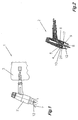
Fig. 1 eine schematische Darstellung eines Schweißbrenners; -
Fig. 2 eine schematische geschnittene Darstellung des Brennerkörpers; -
Fig. 3 eine Explosionsdarstellung der einzelnen Elemente des Brennerkörpers; -
Fig. 4 einen Schrägriss einer Gaslinse für den Brennerkörper; -
Fig. 5 eine Draufsicht auf die Gaslinse; -
Fig. 6 einen Schnitt durch die Gaslinse gemäßFig. 4 ; -
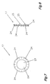
Fig. 7 eine Draufsicht auf ein Einsatzelement für die Gaslinse; -
Fig. 8 eine Seitenansicht des Einsatzelements gemäßFig. 7 in vereinfachter Darstellung; -
Fig. 9 einen Schrägriss eines Siebes für die Gaslinse; -
Fig. 10 eine Draufsicht auf das Gaslinsensieb gemäßFig. 9 in vereinfachter Darstellung; -
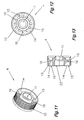
Fig. 11 einen Schrägriss einer Ausführungsvariante der Gaslinse; -
Fig. 12 eine Draufsicht auf die Gaslinse nachFig. 11 ; -
Fig. 13 einen Schnitt durch die Gaslinse nachFig. 11 ; -
Fig. 14 einen Schrägriss einer Lichtbogendüse; -
Fig. 15 eine teilweise geschnittene Darstellung der Lichtbogendüse gemäßFig. 14 ; -
Fig. 16 einen Schnitt durch einen Schweißbrenner mit der Lichtbogendüse gemäßFig. 14 in vereinfachter Darstellung; und -
Fig. 17 eine schematische Darstellung des Schweißbrenners mit der Lichtbogendüse. - In den
Fig. 1 bis 10 ist ein WIG/TIG-Schweißbrenner 1 dargestellt. Der Schweißbrenner 1 besteht aus einem Brennerkörper 2 und einem Brennergriff 3 (strichliert dargestellt). Dabei entsprechen die einzelnen Komponenten des Schweißbrenners 1 dem Aufbau gemäß dem Stand der Technik, sodass auf diese Komponenten und deren Funktion nicht mehr näher eingegangen wird. - Bei der Erfindung handelt es sich um eine Detaillösung für ein Gaslinse 4 im Brennerkörper 2, welche für die Verteilung des über Gasführungskanäle 5 im Grundelement 6 zugeführten Gases 7 verwendet wird. Das über das Grundelement 6 zugeführte Gas 7 strömt vom Grundelement 6 in die Gaslinse 4 ein, und wird anschließend über den Querschnitt der Gaslinse 4 verteilt. Dadurch wird beim Austritt des Gases 7 aus der Gaslinse 4 und somit beim Eintritt in einen Innenraum 8 einer Gasdüse 9 eine optimale Gasverteilung in der Gasdüse 9 erreicht. Wesentlich dabei ist, dass die Baugröße der Gaslinse 4 möglichst klein gehalten wird, da damit die gesamte Baugröße des Schweißbrenners 1 verringert und somit die Handhabung des Schweißbrenners 1 wesentlich verbessert werden kann.
- Die Gaslinse 4 besteht aus einem Grundkörper 10, welcher bevorzugt aus Kupfer oder einer Kupferlegierung gebildet ist. Im Zentrum der Gaslinse 4 ist eine durchgehende Öffnung 11 angeordnet, durch die eine Elektrode 12 und gegebenenfalls eine Lichtbogendüse 13 geführt werden können. Weiters weist der Grundkörper 10 eine Vertiefung 14 zur Bildung des Gasverteilungsraums 15 auf. Im Grundkörper 10 sind stirnseitig Bohrungen 16 vorgesehen, die in den Gasverteilungsraum 15 führen. Über die Bohrungen 16 kann das Gas 7 über die Gasführungskanäle 5 vom Grundelement 6 in den Gasverteilungsraum 15 strömen.
- Zur Erreichung einer optimalen Gasverteilung über den gesamten Querschnitt des Gasverteilungsraumes 15 ist im Gasverteilungsraum 15 ein Einsatzelement 17 angeordnet, welches in den
Fig. 7 und 8 im Detail dargestellt ist. Das Einsatzelement 17 wird derart im Gasverteilungsraum 15 angeordnet, dass sich zwischen dem Austrittsbereich der Bohrungen 16 und dem Einsatzelement 17 ein schmaler Hohlraum 18 bildet. Dabei kann das Einsatzelement 17 entsprechende Vorsprünge aufweisen, die eine entsprechende Distanz zur Stirnfläche 19 des Gasverteilungsraumes 15 erzeugen. Es ist aber auch möglich, in der Vertiefung 14 bzw, dem Gasverteilungsraum 15 einen Steg anzuordnen, auf dem ein einfach hergestelltes Einsatzelement 17 aufgesetzt wird. - Anschließend wird mit einer geringen Distanz zum Einsatzelement 17 ein aus dem Stand der Technik bekanntes Gaslinsensieb 20 (
Fig. 9 und 10 ), in den Gasverteilungsraum 15 eingesetzt. Hierbei können am Gaslinsensieb 20 zur Bildung eines Hohlraumes 21 zwischen dem Gaslinsensieb 20 und dem Einsatzelement 17 wiederum Vorsprünge angeordnet werden, die eine entsprechende Distanz zum Einsatzelement 17 bilden oder am Grundkörper 10 Stege angeordnet werden, an welchen das Gaslinsensieb 20 positioniert wird. Bevorzugt erfolgt die Positionierung des Gaslinsensiebes 20 fluchtend zur Stirnfläche 22 des Grundkörpers 10 der Gaslinse 4. Das Gaslinsensieb 20 besteht aus einer Vielzhal kleiner Löcher, durch die das Gas 7 in die Gasdüse 9 strömen kann. Dabei wird einerseits ein gewisser Gasrückstau im Hohlraum 21 zwischen dem Gaslinsensieb 20 und dem Einsatzelement 17 erreicht. Dieser Gasrückstau ist insofern notwendig, dass sich das Gas 7 im Hohlraum 21 vollständig verteilen kann und anschließend durch das Gaslinsensieb 20 vollflächig in die Gasdüse 9 strömen kann. - Damit eine optimale Verteilung des Gases 7 im Hohlraum 21 erreicht wird, weist das Einsatzelement 17 eine entsprechende Form auf, welche im Zentrum eine Bohrung 23 zur Durchführung der Elektrode 12 besitzt, die korrespondierend zur Öffnung 11 im Grundkörper 10 der Gaslinse 4 ausgebildet ist. Wie aus den
Fig. 7 und 8 ersichtlich ist, weist das Einsatzelement 17 fächerförmige Strömungselemente 24 auf, die in Bezug zur Ebene der Bohrung 23 verdreht ausgebildet sind, sodass eine radiale Ablenkung des durchströmenden Gases 7 erfolgt. Daher werden zwischen den einzelnen Strömungselementen 24 Kanäle 25 gebildet, sodass das über die Bohrung 16 in den Hohlraum 18 zwischen dem Einsatzelement 17 und der Stirnfläche des Grundkörpers 10 zugeführte Gas 7 durch diese schräg verlaufenden Kanäle 25 des Einsatzelements 17 in den weiteren Hohlraum 21 zwischen dem Einsatzelement 17 und dem Gaslinsensieb 20 strömen muss. - Durch diese schräg verlaufenden Kanäle 25 wird das durchströmende Gas 7 in Rotation gebracht, sodass sich das Gas 7 in dem weiteren Hohlraum 21 zwischen dem Einsatzelement 17 und dem Gaslinsensieb 20 weiter dreht. Durch diese Gasdrehung wird eine wesentlich bessere Gasverteilung im Hohlraum 21 erreicht. Durch das in Drehung-Versetzen des Gases 7 kann die Größe des Hohlraumes 21 sehr gering gehalten werden. Beispielsweise kann die Distanz zwischen dem Einsatzelement 17 und dem Gasdüsensieb 20 nur 1 mm bis 3 mm betragen. Dies wirkt sich wesentlich auf die gesamte Baugröße der Gaslinse 4 und somit auf die Größe des Brennerkörpers 3 aus.
- Vergleicht man die bekannten Lösungen des Standes der Technik, so weisen die meisten Gaslinsen 4 mehrere derartige Gaslinsensiebe 20 auf, zwischen denen jeweils ein Hohlraum 18 oder 21 gebildet werden muss. Da jedoch beim Stand der Technik immer nur ein gerader Gasstrom durch die Gaslinsensiebe 20 vorhanden ist, müssen für eine gute Gasverteilung die Hohlräume 18 oder 21 wesentlich größer ausgebildet werden, um einen besseren Gasrückstau in den Hohlräumen 18 oder 21 und somit eine bessere Gasverteilung über den Querschnitt zu erreichen. Somit wird beim Stand der Technik eine wesentlich längere Gaslinse 4 benötigt, als es bei der erfindungsgemäßen Gaslinse 4 der Fall ist.
- Bei der erfindungsgemäßen Gaslinse 4 kann die Länge 26 gegenüber derzeit eingesetzten Gaslinsen um die Hälfte reduziert werden. Beispielsweise kann bei optimaler Gasverteilung durch das Einsatzelement 17 die Länge 26 der Gaslinse 4 zwischen 20 mm und 30 mm betragen. Durch diese geringe Baugröße kann nunmehr der gesamte Brennerkörper 2 kleiner und leichter gebaut und somit die Handhabung des Schweißbrenners 1 verbessert werden.
- Ein weiteres Ausführungsbeispiel der Gaslinse 4 ist in den
Fig. 11 bis 13 dargestellt. Der Unterschied zu der zuvor beschriebenen Gaslinse 4 besteht darin, dass auf das Einsatzelement 17 verzichtet wird. Um jedoch wiederum eine Rotation des Gases 7 vor dem Austritt aus dem Gaslinsensieb 20 zu erreichen, verlaufen nunmehr die Bohrungen 16 im Grundkörper 10 der Gaslinse 4 nicht wie üblich geradlinig, sondern es werden die Bohrungen 16 winkelig zur Längsmittelachse der Gasdüse 9 angeordnet, sodass das vom Gasführungskanal 5 zugeführte Gas 7 schräg in den Hohlraum 18 zwischen einer Stirnfläche des Grundkörpers 10 und dem Gaslinsensieb 20 einströmt. Aufgrund des Gasrückstaus im Hohlraum 18 beginnt sich das schräg einströmende Gas 7 im Hohlraum 18 zu drehen und dadurch wird in einem möglichst kleinen Hohlraum 18 eine optimale Gasverteilung über den gesamten Querschnitt erreicht. - In den
Fig. 14 bis 17 ist eine Lichtbogendüse 13 im Detail dargestellt, die für den Einsatz des Schweißbrenners 1 bei Verwendung zweier unterschiedlicher Gase 7 und 27 verwendet werden kann. - Die Lichtbogendüse 13 ist rohrförmig ausgebildet, wobei der Innendurchmesser einen größeren Durchmesser aufweist, als die durch die Lichtbogendüse 13 zu führende Elektrode 12. An einem Ende weist die Lichtbogendüse 13 bevorzugt einen Anschlagsteg 29 auf, über den die Lichtbogendüse 13 in der Gaslinse 4 positioniert werden kann. Die Lichtbogendüse 13 hat zur Aufgabe, ein über das Zentrum 30 des Brennerkörpers 2 zugeführtes erstes Gas 27 möglichst nahe an die Schweißstelle zu führen, ohne dass sich dieses erste Gas 27 mit dem weiteren Gas 7, welches von der Gaslinse 4 über die Gasdüse 9 an die Schweißstelle geführt wird, vermischt wird. Die Lichtbogendüse 13 wird bevorzugt dann eingesetzt, wenn ein Schweißprozess mit zwei unterschiedlichen Gasen 7 und 27 durchgeführt werden soll, wobei das erste Gas 27 zur Stabilisierung des Lichtbogens und das zweite Gas 7, welches um die erste sogenannte Gasglocke angeordnet ist, zum Schutz gegen äußere atmosphärische Einflüsse auf den Schweißprozess dient.
- Durch dieses System mit der Lichtbogendüse 13 kann der Schweißbrenner 1 in einfacher Form auf einen Brenner, der für zwei Gase verwendet werden kann, umgerüstet werden. Somit kann durch Einsetzen einer solchen Lichtbogendüse 13 über die Elektrode 12 bzw. einen Elektrodenführungskanal ein zusätzliches Gas 27 an den Schweißprozess geleitet werden, wobei dieses über die Lichtbogendüse 13 möglichst nahe an den Schweißprozess geführt wird, bevor es mit dem weiteren, über die Gaslinse 4 und die Gasdüse 9 zugeführte Gas 7 in Kontakt kommt. Somit kann je nach Länge der eingesetzten Lichtbogendüse 13 der Kontakt des ersten Gases 27 mit dem zweiten Gas 7 abgestimmt werden.
- Es kann selbstverständlich auch nur ein Gas 7 oder 27 eingesetzt werden und durch den Einsatz der Lichtbogendüse 13 im Zentrum um die Elektrode 12 eine entsprechende dichtere Gasglocke erzeugt werden.
Claims (4)
- Gaslinse (4) für einen WIG/TIG-Schweißbrenner (1) mit einer Gasdüse (9) mit einem bevorzugt einteiligen Grundkörper (10), der im Zentrum eine durchgehende Öffnung (11) für eine Elektrode (12) und Bohrungen (16) für die Zuführung eines Gases (7, 27) aufweist, wobei zur Verteilung des Gases (7, 27) zumindest ein Gaslinsensieb (20) in einem Gasverteilungskanal (15) des Grundkörpers (10) angeordnet ist, wobei im Gasverteilungskanal (15) des Grundköpers (10) ein Einsatzelement (17) mit einer Bohrung (23) im Zentrum zum Durchführen einer nichtabschmelzenden Elektrode (12) angeordnet ist, und wobei in Richtung der Ausströmung des Gases (7, 27) gesehen nach dem Einsatzelement (17) ein Gaslinsensieb (20) angeordnet ist, dadurch gekennzeichnet, dass um die Bohrung (23) fächerförmige Strömungselemente (24) ausgebildet sind, die in Bezug zur Ebene der Bohrung (23) verdreht ausgebildet sind, sodass eine radiale Ablenkung eines durchströmenden Gases (7, 27) erfolgt.
- Gaslinse (4) nach Anspruch 1, dadurch gekennzeichnet, dass der Grundkörper (10) eine Länge zwischen 20 mm und 30 mm aufweist.
- WIG/TIG-Schweißbrenner (1), mit einem Brennergriff (3) und einem Brennerkörper (2), einer Gasdüse (9) und mit einer Gaslinse (4) mit einem bevorzugt einteiligen Grundkörper (10), der im Zentrum eine durchgehende Öffnung (11) für eine Elektrode (12) und Bohrungen (16) für die Zuführung eines Gases (7, 27) aufweist, wobei zur Verteilung des Gases (7, 27) zumindest ein Gaslinsensieb (20) in einem Gasverteilungskanal (15) des Grundkörpers (10) angeordnet ist, dadurch gekennzeichnet, dass im Gasverteilungskanal (15) des Grundkörpers (10) der Gaslinse (4) ein Einsatzelement (17) mit einer Bohrung (23) im Zentrum zum Durchführen der Elektrode (12) angeordnet ist, um welche Bohrung (23) fächerförmige Strömungselemente (24) ausgebildet sind, die in Bezug zur Ebene der Bohrung (23) verdreht ausgebildet sind, sodass eine radiale Ablenkung des durchströmenden Gases (7, 27) erfolgt, und dass in Richtung der Ausströmung des Gases (7, 27) gesehen nach dem Einsatzelement (17) ein Gaslinsensieb (20) angeordnet ist.
- WIG/TIG-Schweißbrenner (1) nach Anspruch 3, dadurch gekennzeichnet, dass im Brennerkörper (3), insbesondere in der Gaslinse (4) eine Lichtbogendüse (13) zur Führung von zwei Gasen (7, 27) zur Bildung eines Zweigas-Schweißbrenners einsetzbar ist.
Applications Claiming Priority (2)
| Application Number | Priority Date | Filing Date | Title |
|---|---|---|---|
| AT0170206A AT504253B1 (de) | 2006-10-12 | 2006-10-12 | Einsatzelement, gaslinse mit einem solchen einsatzelement und schweissbrenner mit einer solchen gaslinse |
| PCT/AT2007/000400 WO2008043114A1 (de) | 2006-10-12 | 2007-08-22 | EINSATZELEMENT, GASLINSE MIT EINEM SOLCHEN EINSATZELEMENT UND SCHWEIßBRENNER MIT EINER SOLCHEN GASLINSE |
Publications (2)
| Publication Number | Publication Date |
|---|---|
| EP2076351A1 EP2076351A1 (de) | 2009-07-08 |
| EP2076351B1 true EP2076351B1 (de) | 2011-02-23 |
Family
ID=38669046
Family Applications (1)
| Application Number | Title | Priority Date | Filing Date |
|---|---|---|---|
| EP07784628A Not-in-force EP2076351B1 (de) | 2006-10-12 | 2007-08-22 | EINSATZELEMENT, GASLINSE MIT EINEM SOLCHEN EINSATZELEMENT UND SCHWEIßBRENNER MIT EINER SOLCHEN GASLINSE |
Country Status (8)
| Country | Link |
|---|---|
| US (1) | US8809723B2 (de) |
| EP (1) | EP2076351B1 (de) |
| CN (1) | CN101522354B (de) |
| AT (2) | AT504253B1 (de) |
| DE (1) | DE502007006557D1 (de) |
| ES (1) | ES2361234T3 (de) |
| RU (1) | RU2404033C1 (de) |
| WO (1) | WO2008043114A1 (de) |
Families Citing this family (15)
| Publication number | Priority date | Publication date | Assignee | Title |
|---|---|---|---|---|
| JPWO2010018778A1 (ja) * | 2008-08-13 | 2012-01-26 | ミヤチテクノス株式会社 | アーク溶接用トーチ |
| US20100193490A1 (en) * | 2009-02-02 | 2010-08-05 | William Louis Arter | Inert gas welding nozzle |
| DE102011016026B4 (de) | 2011-01-13 | 2014-10-02 | Daniel Weiss | Verfahren zur Verhinderung des Auflegierens der Elektrode beim WIG-Schweißen sowie handgeführter WIG-Schweißkopf zur Durchführung des Verfahrens |
| CN105312747A (zh) * | 2014-07-31 | 2016-02-10 | 张建生 | 分体式电极夹 |
| US9833859B2 (en) * | 2014-09-15 | 2017-12-05 | Lincoln Global, Inc. | Electric arc torch with cooling conduit |
| US9338873B1 (en) | 2015-07-13 | 2016-05-10 | Michael Furick | Mesh screen assembly and shield cup for a gas shielded electric arc torch |
| CN105689855A (zh) * | 2016-03-30 | 2016-06-22 | 山东诺博泰智能科技有限公司 | 一种钨极自动更换和磨削一体化装置 |
| CN106001861B (zh) * | 2016-06-15 | 2018-08-07 | 济南尼克焊接技术有限公司 | 一种高效水冷氩弧焊枪 |
| CN105834563B (zh) * | 2016-06-15 | 2018-08-07 | 济南尼克焊接技术有限公司 | 一种高效气冷氩弧焊枪 |
| PL3581316T3 (pl) | 2016-06-15 | 2024-12-23 | Jinan Uniarc Welding Technology Limited | Palnik do spawania tig |
| US12240065B2 (en) | 2016-06-15 | 2025-03-04 | Jinan Uniarc Welding Technology Limited | TIG welding torch |
| US11376684B2 (en) * | 2018-08-12 | 2022-07-05 | Jesse Vidito | Welding torch |
| CN113195144B (zh) * | 2018-12-25 | 2022-09-16 | 株式会社村田溶研 | 点焊用的带窄喷嘴的tig焊枪以及用于该焊枪的电极用喷嘴 |
| FR3106075B1 (fr) * | 2020-01-15 | 2021-12-24 | Polysoude | « Accessoire destiné à une torche TIG conventionnelle pour permettre de la transformer en une torche TIG bicathodes à arc fusionné en version monosource » |
| US11673204B2 (en) | 2020-11-25 | 2023-06-13 | The Esab Group, Inc. | Hyper-TIG welding electrode |
Family Cites Families (21)
| Publication number | Priority date | Publication date | Assignee | Title |
|---|---|---|---|---|
| GB816632A (en) * | 1955-09-01 | 1959-07-15 | Saturn Ind Gases Ltd | Arc welding torch |
| US2866079A (en) * | 1957-02-18 | 1958-12-23 | Westinghouse Electric Corp | Arc welding apparatus |
| US3180967A (en) * | 1963-01-18 | 1965-04-27 | Union Carbide Corp | Gas lens shielded arc torch |
| FR1488981A (fr) * | 1965-07-21 | 1967-07-21 | Perfectionnements au soudage à l'arc électrique en flux protecteur gazeux | |
| GB1451913A (en) * | 1973-09-25 | 1976-10-06 | Clarke Chapman Ltd | Arc welding torch |
| EP0094984A1 (de) | 1982-07-12 | 1983-11-30 | Manfred J. Wallner | Lichtbogenschweiss- oder Schneidbrenner |
| SU1515546A1 (ru) * | 1986-09-04 | 1994-07-30 | С.В. Геллер | Горелка для дуговой сварки в защитных газах |
| DE8904583U1 (de) * | 1989-04-12 | 1989-07-20 | "Schako" Metallwarenfabrik Ferdinand Schad KG Zweigniederlassung Kolbingen, 7201 Kolbingen | Vorrichtung zum Auslassen von Zuluft |
| RU2036058C1 (ru) * | 1992-07-17 | 1995-05-27 | Борис Макарович Егупов | Горелка для дуговой сварки в среде защитных газов |
| US5455401A (en) * | 1994-10-12 | 1995-10-03 | Aerojet General Corporation | Plasma torch electrode |
| ES2165504T3 (es) * | 1995-05-05 | 2002-03-16 | Binzel Alexander Gmbh Co Kg | Caja de lente de gas para sopletes de soldadura al arco o corte con electrodo no fusible. |
| US5772102A (en) * | 1996-04-19 | 1998-06-30 | Tweco Products, Inc. | Gas lens assembly |
| US5893985A (en) * | 1997-03-14 | 1999-04-13 | The Lincoln Electric Company | Plasma arc torch |
| DE19736684A1 (de) * | 1997-08-22 | 1999-02-25 | Bosch Gmbh Robert | Brennstoffeinspritzventil |
| AUPP182498A0 (en) * | 1998-02-16 | 1998-03-12 | Hanna, Richard John | Welding equipment |
| US6123506A (en) * | 1999-01-20 | 2000-09-26 | Pratt & Whitney Canada Corp. | Diffuser pipe assembly |
| JP2001150142A (ja) * | 1999-11-26 | 2001-06-05 | Koike Sanso Kogyo Co Ltd | プラズマトーチ用の電極 |
| US6525288B2 (en) * | 2001-03-20 | 2003-02-25 | Richard B. Rehrig | Gas lens assembly for a gas shielded arc welding torch |
| US6683279B1 (en) * | 2001-12-27 | 2004-01-27 | Delford A. Moerke | Twin MIG welding apparatus |
| RU2242343C1 (ru) * | 2003-05-28 | 2004-12-20 | Открытое акционерное общество Научно-производственное объединение "Искра" | Малогабаритная горелка для сварки неплавящимся электродом |
| US7547861B2 (en) * | 2006-06-09 | 2009-06-16 | Morten Jorgensen | Vortex generator for plasma treatment |
-
2006
- 2006-10-12 AT AT0170206A patent/AT504253B1/de not_active IP Right Cessation
-
2007
- 2007-08-22 CN CN200780038117.7A patent/CN101522354B/zh not_active Expired - Fee Related
- 2007-08-22 EP EP07784628A patent/EP2076351B1/de not_active Not-in-force
- 2007-08-22 WO PCT/AT2007/000400 patent/WO2008043114A1/de not_active Ceased
- 2007-08-22 RU RU2009117462/02A patent/RU2404033C1/ru not_active IP Right Cessation
- 2007-08-22 AT AT07784628T patent/ATE499172T1/de active
- 2007-08-22 US US12/311,480 patent/US8809723B2/en active Active
- 2007-08-22 DE DE502007006557T patent/DE502007006557D1/de active Active
- 2007-08-22 ES ES07784628T patent/ES2361234T3/es active Active
Also Published As
| Publication number | Publication date |
|---|---|
| AT504253B1 (de) | 2008-06-15 |
| DE502007006557D1 (de) | 2011-04-07 |
| WO2008043114A9 (de) | 2009-06-18 |
| US20090277878A1 (en) | 2009-11-12 |
| CN101522354B (zh) | 2011-12-28 |
| CN101522354A (zh) | 2009-09-02 |
| RU2404033C1 (ru) | 2010-11-20 |
| ATE499172T1 (de) | 2011-03-15 |
| WO2008043114A1 (de) | 2008-04-17 |
| AT504253A1 (de) | 2008-04-15 |
| ES2361234T3 (es) | 2011-06-15 |
| EP2076351A1 (de) | 2009-07-08 |
| US8809723B2 (en) | 2014-08-19 |
Similar Documents
| Publication | Publication Date | Title |
|---|---|---|
| EP2076351A1 (de) | EINSATZELEMENT, GASLINSE MIT EINEM SOLCHEN EINSATZELEMENT UND SCHWEIßBRENNER MIT EINER SOLCHEN GASLINSE | |
| EP0363834B1 (de) | Brenner, insbesondere Hochgeschwindigkeitsbrenner | |
| EP1986788B1 (de) | Zweistoffdüse mit kreisförmig angeordneten sekundärluftdüsen | |
| EP2772312B1 (de) | Zweistoffdüse und Verfahren zum Versprühen eines Flüssigkeit-Gas-Gemisches | |
| DE102004064160B4 (de) | Düsenschutzkappe und Anordnungen von Plasmabrennerkomponenten | |
| EP1992414A2 (de) | Sprühdüse | |
| DE10255884B4 (de) | Düsenanordnung | |
| EP2314923A2 (de) | Drallerzeuger | |
| DE1660592A1 (de) | Blasstrahlduese zum Foerdern und/oder Behandeln textiler Fadengebilde | |
| CH664301A5 (de) | Flammspritzbrenner zur verarbeitung pulver- oder drahtfoermiger spritzwerkstoffe. | |
| DE102011011207A1 (de) | Brenner zum gleichmäßigen Erwärmen eines langen Ofens | |
| AT526463A1 (de) | Heißkanalwerkzeug, Spritzgussvorrichtung und Herstellungsverfahren | |
| DE102011102693B4 (de) | Löschdüsenkopf mit Strömungskanal | |
| EP2907582B1 (de) | Verfahren und Düse zum Mischen und Versprühen von medizinischen Fluiden | |
| DE102012014665A1 (de) | Brenner zum Lichtbogendrahtspritzen | |
| DE19926805A1 (de) | Stoffauflauf mit Fluidzudosierung | |
| EP0707175B1 (de) | Verbrennungsvorrichtung mit einer Düse | |
| DE602004005346T2 (de) | Düsenvorrichtung zum eintragen von gasförmigen medien unter einer schicht von flüssigem metall | |
| EP3088087A1 (de) | Sprühdüse und verfahren zum erzeugen von nicht runden sprühkegeln | |
| DE4102072C2 (de) | ||
| EP0068165B2 (de) | Brenner zum thermochemischen Trennen und/oder Abhobeln von Werkstücken aus Stahl | |
| DE2819132C2 (de) | Gasemischender Schneidbrenner | |
| EP3859061B1 (de) | Faserbandaufnahmeeinrichtung | |
| DE3726507A1 (de) | Fadenspleissvorrichtung | |
| DE4430808A1 (de) | Elektroerosions-Schneidvorrichtung |
Legal Events
| Date | Code | Title | Description |
|---|---|---|---|
| PUAI | Public reference made under article 153(3) epc to a published international application that has entered the european phase |
Free format text: ORIGINAL CODE: 0009012 |
|
| 17P | Request for examination filed |
Effective date: 20090323 |
|
| AK | Designated contracting states |
Kind code of ref document: A1 Designated state(s): AT BE BG CH CY CZ DE DK EE ES FI FR GB GR HU IE IS IT LI LT LU LV MC MT NL PL PT RO SE SI SK TR |
|
| 17Q | First examination report despatched |
Effective date: 20100304 |
|
| GRAP | Despatch of communication of intention to grant a patent |
Free format text: ORIGINAL CODE: EPIDOSNIGR1 |
|
| GRAS | Grant fee paid |
Free format text: ORIGINAL CODE: EPIDOSNIGR3 |
|
| GRAA | (expected) grant |
Free format text: ORIGINAL CODE: 0009210 |
|
| AK | Designated contracting states |
Kind code of ref document: B1 Designated state(s): AT BE BG CH CY CZ DE DK EE ES FI FR GB GR HU IE IS IT LI LT LU LV MC MT NL PL PT RO SE SI SK TR |
|
| REG | Reference to a national code |
Ref country code: GB Ref legal event code: FG4D Free format text: NOT ENGLISH |
|
| REG | Reference to a national code |
Ref country code: CH Ref legal event code: EP |
|
| REG | Reference to a national code |
Ref country code: IE Ref legal event code: FG4D Free format text: LANGUAGE OF EP DOCUMENT: GERMAN |
|
| REF | Corresponds to: |
Ref document number: 502007006557 Country of ref document: DE Date of ref document: 20110407 Kind code of ref document: P |
|
| REG | Reference to a national code |
Ref country code: DE Ref legal event code: R096 Ref document number: 502007006557 Country of ref document: DE Effective date: 20110407 |
|
| REG | Reference to a national code |
Ref country code: ES Ref legal event code: FG2A Ref document number: 2361234 Country of ref document: ES Kind code of ref document: T3 Effective date: 20110615 |
|
| REG | Reference to a national code |
Ref country code: NL Ref legal event code: VDEP Effective date: 20110223 |
|
| LTIE | Lt: invalidation of european patent or patent extension |
Effective date: 20110223 |
|
| PG25 | Lapsed in a contracting state [announced via postgrant information from national office to epo] |
Ref country code: PT Free format text: LAPSE BECAUSE OF FAILURE TO SUBMIT A TRANSLATION OF THE DESCRIPTION OR TO PAY THE FEE WITHIN THE PRESCRIBED TIME-LIMIT Effective date: 20110623 Ref country code: GR Free format text: LAPSE BECAUSE OF FAILURE TO SUBMIT A TRANSLATION OF THE DESCRIPTION OR TO PAY THE FEE WITHIN THE PRESCRIBED TIME-LIMIT Effective date: 20110524 Ref country code: LT Free format text: LAPSE BECAUSE OF FAILURE TO SUBMIT A TRANSLATION OF THE DESCRIPTION OR TO PAY THE FEE WITHIN THE PRESCRIBED TIME-LIMIT Effective date: 20110223 Ref country code: SE Free format text: LAPSE BECAUSE OF FAILURE TO SUBMIT A TRANSLATION OF THE DESCRIPTION OR TO PAY THE FEE WITHIN THE PRESCRIBED TIME-LIMIT Effective date: 20110223 Ref country code: LV Free format text: LAPSE BECAUSE OF FAILURE TO SUBMIT A TRANSLATION OF THE DESCRIPTION OR TO PAY THE FEE WITHIN THE PRESCRIBED TIME-LIMIT Effective date: 20110223 |
|
| PG25 | Lapsed in a contracting state [announced via postgrant information from national office to epo] |
Ref country code: BG Free format text: LAPSE BECAUSE OF FAILURE TO SUBMIT A TRANSLATION OF THE DESCRIPTION OR TO PAY THE FEE WITHIN THE PRESCRIBED TIME-LIMIT Effective date: 20110523 Ref country code: CY Free format text: LAPSE BECAUSE OF FAILURE TO SUBMIT A TRANSLATION OF THE DESCRIPTION OR TO PAY THE FEE WITHIN THE PRESCRIBED TIME-LIMIT Effective date: 20110223 Ref country code: FI Free format text: LAPSE BECAUSE OF FAILURE TO SUBMIT A TRANSLATION OF THE DESCRIPTION OR TO PAY THE FEE WITHIN THE PRESCRIBED TIME-LIMIT Effective date: 20110223 Ref country code: NL Free format text: LAPSE BECAUSE OF FAILURE TO SUBMIT A TRANSLATION OF THE DESCRIPTION OR TO PAY THE FEE WITHIN THE PRESCRIBED TIME-LIMIT Effective date: 20110223 Ref country code: SI Free format text: LAPSE BECAUSE OF FAILURE TO SUBMIT A TRANSLATION OF THE DESCRIPTION OR TO PAY THE FEE WITHIN THE PRESCRIBED TIME-LIMIT Effective date: 20110223 |
|
| REG | Reference to a national code |
Ref country code: IE Ref legal event code: FD4D |
|
| PG25 | Lapsed in a contracting state [announced via postgrant information from national office to epo] |
Ref country code: DK Free format text: LAPSE BECAUSE OF FAILURE TO SUBMIT A TRANSLATION OF THE DESCRIPTION OR TO PAY THE FEE WITHIN THE PRESCRIBED TIME-LIMIT Effective date: 20110223 Ref country code: IE Free format text: LAPSE BECAUSE OF FAILURE TO SUBMIT A TRANSLATION OF THE DESCRIPTION OR TO PAY THE FEE WITHIN THE PRESCRIBED TIME-LIMIT Effective date: 20110223 Ref country code: EE Free format text: LAPSE BECAUSE OF FAILURE TO SUBMIT A TRANSLATION OF THE DESCRIPTION OR TO PAY THE FEE WITHIN THE PRESCRIBED TIME-LIMIT Effective date: 20110223 |
|
| PG25 | Lapsed in a contracting state [announced via postgrant information from national office to epo] |
Ref country code: SK Free format text: LAPSE BECAUSE OF FAILURE TO SUBMIT A TRANSLATION OF THE DESCRIPTION OR TO PAY THE FEE WITHIN THE PRESCRIBED TIME-LIMIT Effective date: 20110223 Ref country code: RO Free format text: LAPSE BECAUSE OF FAILURE TO SUBMIT A TRANSLATION OF THE DESCRIPTION OR TO PAY THE FEE WITHIN THE PRESCRIBED TIME-LIMIT Effective date: 20110223 Ref country code: CZ Free format text: LAPSE BECAUSE OF FAILURE TO SUBMIT A TRANSLATION OF THE DESCRIPTION OR TO PAY THE FEE WITHIN THE PRESCRIBED TIME-LIMIT Effective date: 20110223 |
|
| PG25 | Lapsed in a contracting state [announced via postgrant information from national office to epo] |
Ref country code: MT Free format text: LAPSE BECAUSE OF FAILURE TO SUBMIT A TRANSLATION OF THE DESCRIPTION OR TO PAY THE FEE WITHIN THE PRESCRIBED TIME-LIMIT Effective date: 20110223 |
|
| PLBE | No opposition filed within time limit |
Free format text: ORIGINAL CODE: 0009261 |
|
| STAA | Information on the status of an ep patent application or granted ep patent |
Free format text: STATUS: NO OPPOSITION FILED WITHIN TIME LIMIT |
|
| 26N | No opposition filed |
Effective date: 20111124 |
|
| BERE | Be: lapsed |
Owner name: FRONIUS INTERNATIONAL GMBH Effective date: 20110831 |
|
| PG25 | Lapsed in a contracting state [announced via postgrant information from national office to epo] |
Ref country code: PL Free format text: LAPSE BECAUSE OF FAILURE TO SUBMIT A TRANSLATION OF THE DESCRIPTION OR TO PAY THE FEE WITHIN THE PRESCRIBED TIME-LIMIT Effective date: 20110223 |
|
| REG | Reference to a national code |
Ref country code: DE Ref legal event code: R097 Ref document number: 502007006557 Country of ref document: DE Effective date: 20111124 |
|
| PG25 | Lapsed in a contracting state [announced via postgrant information from national office to epo] |
Ref country code: MC Free format text: LAPSE BECAUSE OF NON-PAYMENT OF DUE FEES Effective date: 20110831 |
|
| REG | Reference to a national code |
Ref country code: CH Ref legal event code: PL |
|
| PG25 | Lapsed in a contracting state [announced via postgrant information from national office to epo] |
Ref country code: LI Free format text: LAPSE BECAUSE OF NON-PAYMENT OF DUE FEES Effective date: 20110831 Ref country code: CH Free format text: LAPSE BECAUSE OF NON-PAYMENT OF DUE FEES Effective date: 20110831 |
|
| PG25 | Lapsed in a contracting state [announced via postgrant information from national office to epo] |
Ref country code: BE Free format text: LAPSE BECAUSE OF NON-PAYMENT OF DUE FEES Effective date: 20110831 |
|
| PG25 | Lapsed in a contracting state [announced via postgrant information from national office to epo] |
Ref country code: LU Free format text: LAPSE BECAUSE OF NON-PAYMENT OF DUE FEES Effective date: 20110822 |
|
| PG25 | Lapsed in a contracting state [announced via postgrant information from national office to epo] |
Ref country code: IS Free format text: LAPSE BECAUSE OF FAILURE TO SUBMIT A TRANSLATION OF THE DESCRIPTION OR TO PAY THE FEE WITHIN THE PRESCRIBED TIME-LIMIT Effective date: 20110223 |
|
| PG25 | Lapsed in a contracting state [announced via postgrant information from national office to epo] |
Ref country code: TR Free format text: LAPSE BECAUSE OF FAILURE TO SUBMIT A TRANSLATION OF THE DESCRIPTION OR TO PAY THE FEE WITHIN THE PRESCRIBED TIME-LIMIT Effective date: 20110223 |
|
| REG | Reference to a national code |
Ref country code: AT Ref legal event code: MM01 Ref document number: 499172 Country of ref document: AT Kind code of ref document: T Effective date: 20120831 |
|
| PG25 | Lapsed in a contracting state [announced via postgrant information from national office to epo] |
Ref country code: AT Free format text: LAPSE BECAUSE OF NON-PAYMENT OF DUE FEES Effective date: 20120831 Ref country code: HU Free format text: LAPSE BECAUSE OF FAILURE TO SUBMIT A TRANSLATION OF THE DESCRIPTION OR TO PAY THE FEE WITHIN THE PRESCRIBED TIME-LIMIT Effective date: 20110223 |
|
| PGFP | Annual fee paid to national office [announced via postgrant information from national office to epo] |
Ref country code: ES Payment date: 20130730 Year of fee payment: 7 |
|
| PGFP | Annual fee paid to national office [announced via postgrant information from national office to epo] |
Ref country code: FR Payment date: 20130814 Year of fee payment: 7 Ref country code: GB Payment date: 20130902 Year of fee payment: 7 |
|
| PGFP | Annual fee paid to national office [announced via postgrant information from national office to epo] |
Ref country code: IT Payment date: 20130730 Year of fee payment: 7 |
|
| GBPC | Gb: european patent ceased through non-payment of renewal fee |
Effective date: 20140822 |
|
| PG25 | Lapsed in a contracting state [announced via postgrant information from national office to epo] |
Ref country code: IT Free format text: LAPSE BECAUSE OF NON-PAYMENT OF DUE FEES Effective date: 20140822 |
|
| REG | Reference to a national code |
Ref country code: FR Ref legal event code: ST Effective date: 20150430 |
|
| PG25 | Lapsed in a contracting state [announced via postgrant information from national office to epo] |
Ref country code: GB Free format text: LAPSE BECAUSE OF NON-PAYMENT OF DUE FEES Effective date: 20140822 |
|
| PG25 | Lapsed in a contracting state [announced via postgrant information from national office to epo] |
Ref country code: FR Free format text: LAPSE BECAUSE OF NON-PAYMENT OF DUE FEES Effective date: 20140901 |
|
| REG | Reference to a national code |
Ref country code: ES Ref legal event code: FD2A Effective date: 20160302 |
|
| PG25 | Lapsed in a contracting state [announced via postgrant information from national office to epo] |
Ref country code: ES Free format text: LAPSE BECAUSE OF NON-PAYMENT OF DUE FEES Effective date: 20140823 |
|
| P01 | Opt-out of the competence of the unified patent court (upc) registered |
Effective date: 20230515 |
|
| PGFP | Annual fee paid to national office [announced via postgrant information from national office to epo] |
Ref country code: DE Payment date: 20230828 Year of fee payment: 17 |
|
| REG | Reference to a national code |
Ref country code: DE Ref legal event code: R119 Ref document number: 502007006557 Country of ref document: DE |
|
| PG25 | Lapsed in a contracting state [announced via postgrant information from national office to epo] |
Ref country code: DE Free format text: LAPSE BECAUSE OF NON-PAYMENT OF DUE FEES Effective date: 20250301 |