EP2076351B1 - Élément d'insertion, lentille de gaz équipée de cet élément d'insertion, et chalumeau de soudage pourvu de cette lentille de gaz - Google Patents
Élément d'insertion, lentille de gaz équipée de cet élément d'insertion, et chalumeau de soudage pourvu de cette lentille de gaz Download PDFInfo
- Publication number
- EP2076351B1 EP2076351B1 EP07784628A EP07784628A EP2076351B1 EP 2076351 B1 EP2076351 B1 EP 2076351B1 EP 07784628 A EP07784628 A EP 07784628A EP 07784628 A EP07784628 A EP 07784628A EP 2076351 B1 EP2076351 B1 EP 2076351B1
- Authority
- EP
- European Patent Office
- Prior art keywords
- gas
- lens
- bore
- welding torch
- gas lens
- Prior art date
- Legal status (The legal status is an assumption and is not a legal conclusion. Google has not performed a legal analysis and makes no representation as to the accuracy of the status listed.)
- Not-in-force
Links
Images




Classifications
-
- B—PERFORMING OPERATIONS; TRANSPORTING
- B23—MACHINE TOOLS; METAL-WORKING NOT OTHERWISE PROVIDED FOR
- B23K—SOLDERING OR UNSOLDERING; WELDING; CLADDING OR PLATING BY SOLDERING OR WELDING; CUTTING BY APPLYING HEAT LOCALLY, e.g. FLAME CUTTING; WORKING BY LASER BEAM
- B23K9/00—Arc welding or cutting
- B23K9/16—Arc welding or cutting making use of shielding gas
- B23K9/167—Arc welding or cutting making use of shielding gas and of a non-consumable electrode
-
- B—PERFORMING OPERATIONS; TRANSPORTING
- B23—MACHINE TOOLS; METAL-WORKING NOT OTHERWISE PROVIDED FOR
- B23K—SOLDERING OR UNSOLDERING; WELDING; CLADDING OR PLATING BY SOLDERING OR WELDING; CUTTING BY APPLYING HEAT LOCALLY, e.g. FLAME CUTTING; WORKING BY LASER BEAM
- B23K9/00—Arc welding or cutting
- B23K9/24—Features related to electrodes
-
- B—PERFORMING OPERATIONS; TRANSPORTING
- B23—MACHINE TOOLS; METAL-WORKING NOT OTHERWISE PROVIDED FOR
- B23K—SOLDERING OR UNSOLDERING; WELDING; CLADDING OR PLATING BY SOLDERING OR WELDING; CUTTING BY APPLYING HEAT LOCALLY, e.g. FLAME CUTTING; WORKING BY LASER BEAM
- B23K9/00—Arc welding or cutting
- B23K9/24—Features related to electrodes
- B23K9/28—Supporting devices for electrodes
- B23K9/285—Cooled electrode holders
-
- B—PERFORMING OPERATIONS; TRANSPORTING
- B23—MACHINE TOOLS; METAL-WORKING NOT OTHERWISE PROVIDED FOR
- B23K—SOLDERING OR UNSOLDERING; WELDING; CLADDING OR PLATING BY SOLDERING OR WELDING; CUTTING BY APPLYING HEAT LOCALLY, e.g. FLAME CUTTING; WORKING BY LASER BEAM
- B23K9/00—Arc welding or cutting
- B23K9/24—Features related to electrodes
- B23K9/28—Supporting devices for electrodes
- B23K9/29—Supporting devices adapted for making use of shielding means
-
- B—PERFORMING OPERATIONS; TRANSPORTING
- B23—MACHINE TOOLS; METAL-WORKING NOT OTHERWISE PROVIDED FOR
- B23K—SOLDERING OR UNSOLDERING; WELDING; CLADDING OR PLATING BY SOLDERING OR WELDING; CUTTING BY APPLYING HEAT LOCALLY, e.g. FLAME CUTTING; WORKING BY LASER BEAM
- B23K9/00—Arc welding or cutting
- B23K9/24—Features related to electrodes
- B23K9/28—Supporting devices for electrodes
- B23K9/29—Supporting devices adapted for making use of shielding means
- B23K9/291—Supporting devices adapted for making use of shielding means the shielding means being a gas
-
- B—PERFORMING OPERATIONS; TRANSPORTING
- B23—MACHINE TOOLS; METAL-WORKING NOT OTHERWISE PROVIDED FOR
- B23K—SOLDERING OR UNSOLDERING; WELDING; CLADDING OR PLATING BY SOLDERING OR WELDING; CUTTING BY APPLYING HEAT LOCALLY, e.g. FLAME CUTTING; WORKING BY LASER BEAM
- B23K9/00—Arc welding or cutting
- B23K9/24—Features related to electrodes
- B23K9/28—Supporting devices for electrodes
- B23K9/29—Supporting devices adapted for making use of shielding means
- B23K9/291—Supporting devices adapted for making use of shielding means the shielding means being a gas
- B23K9/296—Supporting devices adapted for making use of shielding means the shielding means being a gas using non-consumable electrodes
Definitions
- the invention relates to a gas lens for a TIG / TIG welding torch and a TIG / TIG welding torch according to the preambles of claims 1 and 3.
- TIG / TIG welding torches are known in which a gas lens is used in the burner body, in the gas distribution chamber a plurality of gas lens sieves are arranged.
- the gas lens sieves are always arranged at a distance from each other, so that the gas can spread accordingly in the cavity between the main body of the gas lens and gas lens sieve, and between the gas lens sieves.
- the US 2002/0134760 A1 describes a gas lens for a TIG / TIG welding torch, which has radial bores for the supply of a gas.
- the disadvantage here is that for a good gas distribution, a correspondingly large cavity between the gas lens filters must be provided, whereby the size of the gas lens must be made correspondingly large. Furthermore, it is necessary in the prior art to use multiple gas lens sieves to form a corresponding backwater. If, for example, only one gas lens sieve is used, it may happen that the inflowing gas does not spread uniformly over the cross section in the cavity in front of the gas lens sieve and thus does not flow uniformly into the adjoining gas nozzle through the gas lens sieve. This can be prevented by the use of multiple gas lens sieves, since in each cavity before the gas lens sieves a corresponding backflow occurs and thus a distribution of the gas is carried out. The more gas lens sieves are used, the better the gas distribution over the cross section.
- the object of the invention is to provide a gas lens for a TIG / TIG welding torch and a TIG / TIG welding torch, through which a better gas distribution over the Cross section of the gas lens and thus over the cross section of the gas nozzle can be achieved.
- the size and weight of the components should be as low as possible.
- the object of the invention is achieved by an above-mentioned gas lens, wherein in the gas distribution channel of the Grundköpers an insert element is arranged with a bore in the center for performing a non-consumable electrode to which bore fan-shaped flow elements are formed, which rotates with respect to the plane of the bore are formed so that a radial deflection of a gas flowing through takes place, and seen in the direction of the outflow of the gas after the insert element, a gas lens screen is arranged.
- the insert element is used in a gas lens, the gas flowing in rectilinearly is deflected via the fan-shaped flow elements. This will bring the gas into rotation and achieve a better distribution of the gas.
- Such a reduction of the gas lens to a length of for example 20 to 30 mm, the size and weight, and the burner body of the welding torch is reduced and improves the handling of the welding torch.
- the object of the invention is also achieved by an above-mentioned TIG / TIG welding torch, in which the gas lens is designed according to claims 1 to 2.
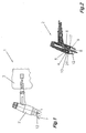
- a TIG / TIG welding torch 1 is shown.
- the welding torch 1 consists of a burner body 2 and a burner handle 3 (shown in dashed lines).
- the individual components of the welding torch 1 correspond to the structure according to the prior art, so that these components and their function will not be discussed in more detail.
- a gas lens 4 in the burner body 2 which is used for the distribution of the gas 7 supplied via gas guide channels 5 in the base element 6.
- the gas 7 supplied via the base element 6 flows from the base element 6 into the gas lens 4, and is then distributed over the cross section of the gas lens 4.
- an optimal gas distribution in the gas nozzle 9 is achieved at the outlet of the gas 7 from the gas lens 4 and thus upon entry into an interior 8 of a gas nozzle 9.
- the size of the gas lens 4 is kept as small as possible, since it reduces the overall size of the welding torch 1 and thus the handling of the welding torch 1 can be substantially improved.
- the gas lens 4 consists of a base body 10, which is preferably formed of copper or a copper alloy. In the center of the gas lens 4, a through opening 11 is arranged through which an electrode 12 and optionally an arc nozzle 13 can be performed. Furthermore, the main body 10 has a recess 14 for forming the gas distribution chamber 15. In the base 10 holes 16 are provided on the front side, the lead into the gas distribution chamber 15. Via the bores 16, the gas 7 can flow via the gas guide channels 5 from the base element 6 into the gas distribution chamber 15.
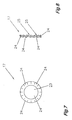
- an insert element 17 is arranged in the gas distribution chamber 15, which is in the FIGS. 7 and 8 is shown in detail.
- the insert element 17 is arranged in the gas distribution chamber 15 such that a narrow cavity 18 is formed between the exit region of the bores 16 and the insert element 17.
- the insert element 17 may have corresponding projections which generate a corresponding distance to the end face 19 of the gas distribution chamber 15.
- a gas lens sieve 20 (known from the prior art) is provided.
- FIGS. 9 and 10 are inserted into the gas distribution space 15.
- projections can again be arranged on the gas lens sieve 20 for forming a cavity 21 between the gas lens sieve 20 and the insert element 17, which form a corresponding distance from the insert element 17 or are arranged on the main body 10 webs on which the gas lens sieve 20 is positioned.
- the positioning of the gas lens sieve 20 is aligned with the end face 22 of the main body 10 of the gas lens 4.
- the gas lens sieve 20 consists of a plurality of small holes through which the gas 7 can flow into the gas nozzle 9.
- the insert member 17 has a corresponding shape, which has a bore 23 for passage of the electrode 12 in the center, which is formed corresponding to the opening 11 in the base body 10 of the gas lens 4.
- the insert member 17 has fan-shaped flow elements 24, which are formed twisted with respect to the plane of the bore 23, so that a radial deflection of the gas flowing through 7 takes place.
- the gas flowing through 7 is brought into rotation, so that the gas 7 further rotates in the further cavity 21 between the insert member 17 and the gas lens sieve 20.
- the size of the cavity 21 can be kept very small.
- the distance between the insert element 17 and the gas nozzle screen 20 may be only 1 mm to 3 mm. This has a significant effect on the overall size of the gas lens 4 and thus on the size of the burner body 3.
- the length 26 can be reduced by half compared with currently used gas lenses.
- the length 26 of the gas lens 4 may be between 20 mm and 30 mm. Due to this small size now the entire Burner body 2 smaller and lighter built and thus the handling of the welding torch 1 can be improved.
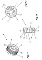
- FIG. 11 to 13 Another embodiment of the gas lens 4 is in the Fig. 11 to 13 shown.
- the insert element 17 is dispensed with.
- the holes 16 in the base body 10 of the gas lens 4 are not straight as usual, but the holes 16 are arranged at an angle to the longitudinal central axis of the gas nozzle 9, so that the supplied from the gas guide channel 5 gas 7 obliquely flows into the cavity 18 between an end face of the base body 10 and the gas lens sieve 20. Due to the gas backpressure in the cavity 18, the obliquely flowing gas 7 begins to rotate in the cavity 18 and thereby an optimal gas distribution over the entire cross section is achieved in the smallest possible cavity 18.
- FIGS. 14 to 17 a Lichtbogendüse 13 is shown in detail, which can be used for the use of the welding torch 1 when using two different gases 7 and 27.
- the arc nozzle 13 is tubular, wherein the inner diameter has a larger diameter than the electrode 12 to be led through the arc nozzle 13.
- the arc nozzle 13 preferably has a stop ridge 29, via which the arc nozzle 13 are positioned in the gas lens 4 can.
- the purpose of the arc nozzle 13 is to guide a first gas 27, which is supplied via the center 30 of the burner body 2, as close as possible to the weld, without this first gas 27 reacting with the further gas 7, which flows from the gas lens 4 via the gas nozzle 9 the weld is passed, is mixed.
- the arc nozzle 13 is preferably used when a welding process with two different gases 7 and 27 is to be performed, the first gas 27 for stabilizing the arc and the second gas 7, which is arranged around the first so-called gas bell, for protection against external atmospheric influences on the welding process.
- the welding torch 1 in a simple form can be retrofitted to a burner that can be used for two gases.
- an additional gas 27 are passed to the welding process, which is guided via the arc nozzle 13 as close to the welding process, before it with the other, via the gas lens 4th and the gas nozzle 9 supplied gas 7 comes into contact.
- the contact of the first gas 27 with the second gas 7 can be tuned.
Landscapes
- Engineering & Computer Science (AREA)
- Physics & Mathematics (AREA)
- Plasma & Fusion (AREA)
- Mechanical Engineering (AREA)
- Arc Welding In General (AREA)
- Laser Beam Processing (AREA)
Claims (4)
- Lentille de gaz (4) pour un chalumeau de soudage à l'arc TIG (1), comprenant une buse à gaz (9) avec un corps de base (10) de préférence d'une seule pièce, qui présente, au centre, une ouverture traversante (11) pour une électrode (12) et des perçages (16) pour l'acheminement d'un gaz (7, 27), dans laquelle, pour distribuer le gaz (7, 27), au moins un tamis de lentille de gaz (20) est agencé dans un canal de distribution de gaz (15) du corps de base (10), dans laquelle un élément rapporté (17) ayant un perçage (23) est ménagé au centre du canal de distribution de gaz (15) du corps de base (10) pour y faire passer une électrode non fusible (12) et dans laquelle, observé dans le sens d'échappement du gaz (7, 27), un tamis de lentille de gaz (20) est agencé après l'élément rapporté (17), caractérisée en ce qu'autour du perçage (23) sont formés des éléments d'écoulement (24) en forme d'éventail, qui sont déformés par rapport au plan du perçage (23) de manière à provoquer une déviation radiale d'un gaz de passage (7, 27).
- Lentille de gaz (4) selon la revendication 1, caractérisée en ce que le corps de base (10) présente une longueur comprise entre 20 mm et 30 mm.
- Chalumeau de soudage à l'arc TIG (1), comprenant un manche de chalumeau (3) et un corps de chalumeau (2), une buse à gaz (9) et une lentille de gaz (4) avec un corps de base (10) de préférence d'une seule pièce qui présente, au centre, une ouverture traversante (11) pour une électrode (12) et des perçages (16) pour l'acheminement d'un gaz (7, 27), dans lequel, pour distribuer le gaz (7, 27), au moins un tamis de lentille de gaz (20) est agencé dans un canal de distribution de gaz (15) du corps de base (10), caractérisé en ce qu'un élément rapporté (17) ayant un perçage (23) est agencé au centre du canal de distribution de gaz (15) du corps de base (10) de la lentille de gaz (4) pour faire passer l'électrode (12), autour duquel perçage (23) sont formés des éléments d'écoulement (24) en forme d'éventail, qui sont déformés par rapport au plan du perçage (23) de manière à provoquer une déviation radiale du gaz de passage (7, 27) et en ce qu'observé dans le sens d'échappement du gaz (7, 27), un tamis de lentille de gaz (20) est agencé après l'élément rapporté (17).
- Chalumeau de soudage à l'arc TIG (1) selon la revendication 3, caractérisé en ce que, dans le corps de chalumeau (3), en particulier dans la lentille de gaz (4), on peut insérer une buse à arc électrique (13) pour acheminer deux gaz (7, 27) dans le but de former un chalumeau de soudage à deux gaz.
Applications Claiming Priority (2)
| Application Number | Priority Date | Filing Date | Title |
|---|---|---|---|
| AT0170206A AT504253B1 (de) | 2006-10-12 | 2006-10-12 | Einsatzelement, gaslinse mit einem solchen einsatzelement und schweissbrenner mit einer solchen gaslinse |
| PCT/AT2007/000400 WO2008043114A1 (fr) | 2006-10-12 | 2007-08-22 | Élément d'insertion, lentille de gaz équipée de cet élément d'insertion, et chalumeau de soudage pourvu de cette lentille de gaz |
Publications (2)
| Publication Number | Publication Date |
|---|---|
| EP2076351A1 EP2076351A1 (fr) | 2009-07-08 |
| EP2076351B1 true EP2076351B1 (fr) | 2011-02-23 |
Family
ID=38669046
Family Applications (1)
| Application Number | Title | Priority Date | Filing Date |
|---|---|---|---|
| EP07784628A Not-in-force EP2076351B1 (fr) | 2006-10-12 | 2007-08-22 | Élément d'insertion, lentille de gaz équipée de cet élément d'insertion, et chalumeau de soudage pourvu de cette lentille de gaz |
Country Status (8)
| Country | Link |
|---|---|
| US (1) | US8809723B2 (fr) |
| EP (1) | EP2076351B1 (fr) |
| CN (1) | CN101522354B (fr) |
| AT (2) | AT504253B1 (fr) |
| DE (1) | DE502007006557D1 (fr) |
| ES (1) | ES2361234T3 (fr) |
| RU (1) | RU2404033C1 (fr) |
| WO (1) | WO2008043114A1 (fr) |
Families Citing this family (15)
| Publication number | Priority date | Publication date | Assignee | Title |
|---|---|---|---|---|
| CN102123815B (zh) * | 2008-08-13 | 2016-04-13 | 米亚基株式会社 | 电弧焊接用焊枪 |
| US20100193490A1 (en) * | 2009-02-02 | 2010-08-05 | William Louis Arter | Inert gas welding nozzle |
| DE102011016026B4 (de) | 2011-01-13 | 2014-10-02 | Daniel Weiss | Verfahren zur Verhinderung des Auflegierens der Elektrode beim WIG-Schweißen sowie handgeführter WIG-Schweißkopf zur Durchführung des Verfahrens |
| CN105312747A (zh) * | 2014-07-31 | 2016-02-10 | 张建生 | 分体式电极夹 |
| US9833859B2 (en) * | 2014-09-15 | 2017-12-05 | Lincoln Global, Inc. | Electric arc torch with cooling conduit |
| US9338873B1 (en) | 2015-07-13 | 2016-05-10 | Michael Furick | Mesh screen assembly and shield cup for a gas shielded electric arc torch |
| CN105689855A (zh) * | 2016-03-30 | 2016-06-22 | 山东诺博泰智能科技有限公司 | 一种钨极自动更换和磨削一体化装置 |
| RU2750597C2 (ru) | 2016-06-15 | 2021-06-29 | Джинан Юниарк Уэлдинг Текнолоджи Лимитед, КНР | Сварочная горелка tig |
| CN106001861B (zh) * | 2016-06-15 | 2018-08-07 | 济南尼克焊接技术有限公司 | 一种高效水冷氩弧焊枪 |
| CN105834563B (zh) * | 2016-06-15 | 2018-08-07 | 济南尼克焊接技术有限公司 | 一种高效气冷氩弧焊枪 |
| US12240065B2 (en) | 2016-06-15 | 2025-03-04 | Jinan Uniarc Welding Technology Limited | TIG welding torch |
| US11376684B2 (en) * | 2018-08-12 | 2022-07-05 | Jesse Vidito | Welding torch |
| JP6860260B2 (ja) * | 2018-12-25 | 2021-04-14 | 株式会社ムラタ溶研 | スポット溶接用の狭窄ノズル付きtig溶接トーチ及びこれに用いられる電極用ノズル |
| FR3106075B1 (fr) * | 2020-01-15 | 2021-12-24 | Polysoude | « Accessoire destiné à une torche TIG conventionnelle pour permettre de la transformer en une torche TIG bicathodes à arc fusionné en version monosource » |
| US11673204B2 (en) | 2020-11-25 | 2023-06-13 | The Esab Group, Inc. | Hyper-TIG welding electrode |
Family Cites Families (21)
| Publication number | Priority date | Publication date | Assignee | Title |
|---|---|---|---|---|
| GB816632A (en) * | 1955-09-01 | 1959-07-15 | Saturn Ind Gases Ltd | Arc welding torch |
| US2866079A (en) * | 1957-02-18 | 1958-12-23 | Westinghouse Electric Corp | Arc welding apparatus |
| US3180967A (en) * | 1963-01-18 | 1965-04-27 | Union Carbide Corp | Gas lens shielded arc torch |
| FR1488981A (fr) * | 1965-07-21 | 1967-07-21 | Perfectionnements au soudage à l'arc électrique en flux protecteur gazeux | |
| GB1451913A (en) * | 1973-09-25 | 1976-10-06 | Clarke Chapman Ltd | Arc welding torch |
| EP0094984A1 (fr) | 1982-07-12 | 1983-11-30 | Manfred J. Wallner | Chalumeau soudeur ou coupeur à l'arc |
| SU1515546A1 (ru) * | 1986-09-04 | 1994-07-30 | С.В. Геллер | Горелка для дуговой сварки в защитных газах |
| DE8904583U1 (de) * | 1989-04-12 | 1989-07-20 | "Schako" Metallwarenfabrik Ferdinand Schad KG Zweigniederlassung Kolbingen, 7201 Kolbingen | Vorrichtung zum Auslassen von Zuluft |
| RU2036058C1 (ru) * | 1992-07-17 | 1995-05-27 | Борис Макарович Егупов | Горелка для дуговой сварки в среде защитных газов |
| US5455401A (en) * | 1994-10-12 | 1995-10-03 | Aerojet General Corporation | Plasma torch electrode |
| WO1996034716A1 (fr) * | 1995-05-05 | 1996-11-07 | Alexander Binzel Gmbh & Co. Kg | Boitier de lentille de gaz pour chalumeaux soudeurs a l'arc ou coupeurs a electrode non fusible |
| US5772102A (en) * | 1996-04-19 | 1998-06-30 | Tweco Products, Inc. | Gas lens assembly |
| US5893985A (en) * | 1997-03-14 | 1999-04-13 | The Lincoln Electric Company | Plasma arc torch |
| DE19736684A1 (de) * | 1997-08-22 | 1999-02-25 | Bosch Gmbh Robert | Brennstoffeinspritzventil |
| AUPP182498A0 (en) * | 1998-02-16 | 1998-03-12 | Hanna, Richard John | Welding equipment |
| US6123506A (en) * | 1999-01-20 | 2000-09-26 | Pratt & Whitney Canada Corp. | Diffuser pipe assembly |
| JP2001150142A (ja) * | 1999-11-26 | 2001-06-05 | Koike Sanso Kogyo Co Ltd | プラズマトーチ用の電極 |
| US6525288B2 (en) * | 2001-03-20 | 2003-02-25 | Richard B. Rehrig | Gas lens assembly for a gas shielded arc welding torch |
| US6683279B1 (en) * | 2001-12-27 | 2004-01-27 | Delford A. Moerke | Twin MIG welding apparatus |
| RU2242343C1 (ru) * | 2003-05-28 | 2004-12-20 | Открытое акционерное общество Научно-производственное объединение "Искра" | Малогабаритная горелка для сварки неплавящимся электродом |
| US7547861B2 (en) * | 2006-06-09 | 2009-06-16 | Morten Jorgensen | Vortex generator for plasma treatment |
-
2006
- 2006-10-12 AT AT0170206A patent/AT504253B1/de not_active IP Right Cessation
-
2007
- 2007-08-22 CN CN200780038117.7A patent/CN101522354B/zh not_active Expired - Fee Related
- 2007-08-22 RU RU2009117462/02A patent/RU2404033C1/ru not_active IP Right Cessation
- 2007-08-22 US US12/311,480 patent/US8809723B2/en active Active
- 2007-08-22 EP EP07784628A patent/EP2076351B1/fr not_active Not-in-force
- 2007-08-22 ES ES07784628T patent/ES2361234T3/es active Active
- 2007-08-22 DE DE502007006557T patent/DE502007006557D1/de active Active
- 2007-08-22 AT AT07784628T patent/ATE499172T1/de active
- 2007-08-22 WO PCT/AT2007/000400 patent/WO2008043114A1/fr not_active Ceased
Also Published As
| Publication number | Publication date |
|---|---|
| US20090277878A1 (en) | 2009-11-12 |
| ES2361234T3 (es) | 2011-06-15 |
| WO2008043114A1 (fr) | 2008-04-17 |
| US8809723B2 (en) | 2014-08-19 |
| WO2008043114A9 (fr) | 2009-06-18 |
| RU2404033C1 (ru) | 2010-11-20 |
| AT504253B1 (de) | 2008-06-15 |
| DE502007006557D1 (de) | 2011-04-07 |
| AT504253A1 (de) | 2008-04-15 |
| EP2076351A1 (fr) | 2009-07-08 |
| CN101522354B (zh) | 2011-12-28 |
| CN101522354A (zh) | 2009-09-02 |
| ATE499172T1 (de) | 2011-03-15 |
Similar Documents
| Publication | Publication Date | Title |
|---|---|---|
| EP2076351B1 (fr) | Élément d'insertion, lentille de gaz équipée de cet élément d'insertion, et chalumeau de soudage pourvu de cette lentille de gaz | |
| EP0363834B1 (fr) | Brûleur, particulièrement brûleur à haute vitesse | |
| EP2772312B1 (fr) | Buse à deux composants et procédé de pulvérisation d'un mélange liquide-gaz | |
| DE102004064160B4 (de) | Düsenschutzkappe und Anordnungen von Plasmabrennerkomponenten | |
| DE202011103257U1 (de) | Plasma-Lichtbogenbrenner | |
| DE10255884B4 (de) | Düsenanordnung | |
| EP2314923A2 (fr) | Tourbillonneur | |
| DE1660592A1 (de) | Blasstrahlduese zum Foerdern und/oder Behandeln textiler Fadengebilde | |
| CH664301A5 (de) | Flammspritzbrenner zur verarbeitung pulver- oder drahtfoermiger spritzwerkstoffe. | |
| DE102011011207A1 (de) | Brenner zum gleichmäßigen Erwärmen eines langen Ofens | |
| AT526463A1 (de) | Heißkanalwerkzeug, Spritzgussvorrichtung und Herstellungsverfahren | |
| DE102011102693B4 (de) | Löschdüsenkopf mit Strömungskanal | |
| EP2907582B1 (fr) | Procédé et buse permettant de mélanger et de pulvériser des fluides médicaux | |
| DE102012014665A1 (de) | Brenner zum Lichtbogendrahtspritzen | |
| DE19926805A1 (de) | Stoffauflauf mit Fluidzudosierung | |
| DE602004005346T2 (de) | Düsenvorrichtung zum eintragen von gasförmigen medien unter einer schicht von flüssigem metall | |
| EP3088087A1 (fr) | Buse de pulverisation et procede de production de cones de pulverisation non arrondis | |
| EP0068165B2 (fr) | Brûleur pour découper et/ou dégrossir thermochimiquement des pièces à usiner en acier | |
| DE2819132C2 (de) | Gasemischender Schneidbrenner | |
| EP3859061B1 (fr) | Dispositif de réception d'une mèche de fibres | |
| DE3726507A1 (de) | Fadenspleissvorrichtung | |
| DE4430808A1 (de) | Elektroerosions-Schneidvorrichtung | |
| DE102014001199A1 (de) | Innenbrenner | |
| DE4026993A1 (de) | Luftduese zum einwirken von druckluft auf fasermaterial | |
| WO2009030431A2 (fr) | Tête d'usinage au laser pour usiner une pièce au moyen d'un faisceau laser |
Legal Events
| Date | Code | Title | Description |
|---|---|---|---|
| PUAI | Public reference made under article 153(3) epc to a published international application that has entered the european phase |
Free format text: ORIGINAL CODE: 0009012 |
|
| 17P | Request for examination filed |
Effective date: 20090323 |
|
| AK | Designated contracting states |
Kind code of ref document: A1 Designated state(s): AT BE BG CH CY CZ DE DK EE ES FI FR GB GR HU IE IS IT LI LT LU LV MC MT NL PL PT RO SE SI SK TR |
|
| 17Q | First examination report despatched |
Effective date: 20100304 |
|
| GRAP | Despatch of communication of intention to grant a patent |
Free format text: ORIGINAL CODE: EPIDOSNIGR1 |
|
| GRAS | Grant fee paid |
Free format text: ORIGINAL CODE: EPIDOSNIGR3 |
|
| GRAA | (expected) grant |
Free format text: ORIGINAL CODE: 0009210 |
|
| AK | Designated contracting states |
Kind code of ref document: B1 Designated state(s): AT BE BG CH CY CZ DE DK EE ES FI FR GB GR HU IE IS IT LI LT LU LV MC MT NL PL PT RO SE SI SK TR |
|
| REG | Reference to a national code |
Ref country code: GB Ref legal event code: FG4D Free format text: NOT ENGLISH |
|
| REG | Reference to a national code |
Ref country code: CH Ref legal event code: EP |
|
| REG | Reference to a national code |
Ref country code: IE Ref legal event code: FG4D Free format text: LANGUAGE OF EP DOCUMENT: GERMAN |
|
| REF | Corresponds to: |
Ref document number: 502007006557 Country of ref document: DE Date of ref document: 20110407 Kind code of ref document: P |
|
| REG | Reference to a national code |
Ref country code: DE Ref legal event code: R096 Ref document number: 502007006557 Country of ref document: DE Effective date: 20110407 |
|
| REG | Reference to a national code |
Ref country code: ES Ref legal event code: FG2A Ref document number: 2361234 Country of ref document: ES Kind code of ref document: T3 Effective date: 20110615 |
|
| REG | Reference to a national code |
Ref country code: NL Ref legal event code: VDEP Effective date: 20110223 |
|
| LTIE | Lt: invalidation of european patent or patent extension |
Effective date: 20110223 |
|
| PG25 | Lapsed in a contracting state [announced via postgrant information from national office to epo] |
Ref country code: PT Free format text: LAPSE BECAUSE OF FAILURE TO SUBMIT A TRANSLATION OF THE DESCRIPTION OR TO PAY THE FEE WITHIN THE PRESCRIBED TIME-LIMIT Effective date: 20110623 Ref country code: GR Free format text: LAPSE BECAUSE OF FAILURE TO SUBMIT A TRANSLATION OF THE DESCRIPTION OR TO PAY THE FEE WITHIN THE PRESCRIBED TIME-LIMIT Effective date: 20110524 Ref country code: LT Free format text: LAPSE BECAUSE OF FAILURE TO SUBMIT A TRANSLATION OF THE DESCRIPTION OR TO PAY THE FEE WITHIN THE PRESCRIBED TIME-LIMIT Effective date: 20110223 Ref country code: SE Free format text: LAPSE BECAUSE OF FAILURE TO SUBMIT A TRANSLATION OF THE DESCRIPTION OR TO PAY THE FEE WITHIN THE PRESCRIBED TIME-LIMIT Effective date: 20110223 Ref country code: LV Free format text: LAPSE BECAUSE OF FAILURE TO SUBMIT A TRANSLATION OF THE DESCRIPTION OR TO PAY THE FEE WITHIN THE PRESCRIBED TIME-LIMIT Effective date: 20110223 |
|
| PG25 | Lapsed in a contracting state [announced via postgrant information from national office to epo] |
Ref country code: BG Free format text: LAPSE BECAUSE OF FAILURE TO SUBMIT A TRANSLATION OF THE DESCRIPTION OR TO PAY THE FEE WITHIN THE PRESCRIBED TIME-LIMIT Effective date: 20110523 Ref country code: CY Free format text: LAPSE BECAUSE OF FAILURE TO SUBMIT A TRANSLATION OF THE DESCRIPTION OR TO PAY THE FEE WITHIN THE PRESCRIBED TIME-LIMIT Effective date: 20110223 Ref country code: FI Free format text: LAPSE BECAUSE OF FAILURE TO SUBMIT A TRANSLATION OF THE DESCRIPTION OR TO PAY THE FEE WITHIN THE PRESCRIBED TIME-LIMIT Effective date: 20110223 Ref country code: NL Free format text: LAPSE BECAUSE OF FAILURE TO SUBMIT A TRANSLATION OF THE DESCRIPTION OR TO PAY THE FEE WITHIN THE PRESCRIBED TIME-LIMIT Effective date: 20110223 Ref country code: SI Free format text: LAPSE BECAUSE OF FAILURE TO SUBMIT A TRANSLATION OF THE DESCRIPTION OR TO PAY THE FEE WITHIN THE PRESCRIBED TIME-LIMIT Effective date: 20110223 |
|
| REG | Reference to a national code |
Ref country code: IE Ref legal event code: FD4D |
|
| PG25 | Lapsed in a contracting state [announced via postgrant information from national office to epo] |
Ref country code: DK Free format text: LAPSE BECAUSE OF FAILURE TO SUBMIT A TRANSLATION OF THE DESCRIPTION OR TO PAY THE FEE WITHIN THE PRESCRIBED TIME-LIMIT Effective date: 20110223 Ref country code: IE Free format text: LAPSE BECAUSE OF FAILURE TO SUBMIT A TRANSLATION OF THE DESCRIPTION OR TO PAY THE FEE WITHIN THE PRESCRIBED TIME-LIMIT Effective date: 20110223 Ref country code: EE Free format text: LAPSE BECAUSE OF FAILURE TO SUBMIT A TRANSLATION OF THE DESCRIPTION OR TO PAY THE FEE WITHIN THE PRESCRIBED TIME-LIMIT Effective date: 20110223 |
|
| PG25 | Lapsed in a contracting state [announced via postgrant information from national office to epo] |
Ref country code: SK Free format text: LAPSE BECAUSE OF FAILURE TO SUBMIT A TRANSLATION OF THE DESCRIPTION OR TO PAY THE FEE WITHIN THE PRESCRIBED TIME-LIMIT Effective date: 20110223 Ref country code: RO Free format text: LAPSE BECAUSE OF FAILURE TO SUBMIT A TRANSLATION OF THE DESCRIPTION OR TO PAY THE FEE WITHIN THE PRESCRIBED TIME-LIMIT Effective date: 20110223 Ref country code: CZ Free format text: LAPSE BECAUSE OF FAILURE TO SUBMIT A TRANSLATION OF THE DESCRIPTION OR TO PAY THE FEE WITHIN THE PRESCRIBED TIME-LIMIT Effective date: 20110223 |
|
| PG25 | Lapsed in a contracting state [announced via postgrant information from national office to epo] |
Ref country code: MT Free format text: LAPSE BECAUSE OF FAILURE TO SUBMIT A TRANSLATION OF THE DESCRIPTION OR TO PAY THE FEE WITHIN THE PRESCRIBED TIME-LIMIT Effective date: 20110223 |
|
| PLBE | No opposition filed within time limit |
Free format text: ORIGINAL CODE: 0009261 |
|
| STAA | Information on the status of an ep patent application or granted ep patent |
Free format text: STATUS: NO OPPOSITION FILED WITHIN TIME LIMIT |
|
| 26N | No opposition filed |
Effective date: 20111124 |
|
| BERE | Be: lapsed |
Owner name: FRONIUS INTERNATIONAL GMBH Effective date: 20110831 |
|
| PG25 | Lapsed in a contracting state [announced via postgrant information from national office to epo] |
Ref country code: PL Free format text: LAPSE BECAUSE OF FAILURE TO SUBMIT A TRANSLATION OF THE DESCRIPTION OR TO PAY THE FEE WITHIN THE PRESCRIBED TIME-LIMIT Effective date: 20110223 |
|
| REG | Reference to a national code |
Ref country code: DE Ref legal event code: R097 Ref document number: 502007006557 Country of ref document: DE Effective date: 20111124 |
|
| PG25 | Lapsed in a contracting state [announced via postgrant information from national office to epo] |
Ref country code: MC Free format text: LAPSE BECAUSE OF NON-PAYMENT OF DUE FEES Effective date: 20110831 |
|
| REG | Reference to a national code |
Ref country code: CH Ref legal event code: PL |
|
| PG25 | Lapsed in a contracting state [announced via postgrant information from national office to epo] |
Ref country code: LI Free format text: LAPSE BECAUSE OF NON-PAYMENT OF DUE FEES Effective date: 20110831 Ref country code: CH Free format text: LAPSE BECAUSE OF NON-PAYMENT OF DUE FEES Effective date: 20110831 |
|
| PG25 | Lapsed in a contracting state [announced via postgrant information from national office to epo] |
Ref country code: BE Free format text: LAPSE BECAUSE OF NON-PAYMENT OF DUE FEES Effective date: 20110831 |
|
| PG25 | Lapsed in a contracting state [announced via postgrant information from national office to epo] |
Ref country code: LU Free format text: LAPSE BECAUSE OF NON-PAYMENT OF DUE FEES Effective date: 20110822 |
|
| PG25 | Lapsed in a contracting state [announced via postgrant information from national office to epo] |
Ref country code: IS Free format text: LAPSE BECAUSE OF FAILURE TO SUBMIT A TRANSLATION OF THE DESCRIPTION OR TO PAY THE FEE WITHIN THE PRESCRIBED TIME-LIMIT Effective date: 20110223 |
|
| PG25 | Lapsed in a contracting state [announced via postgrant information from national office to epo] |
Ref country code: TR Free format text: LAPSE BECAUSE OF FAILURE TO SUBMIT A TRANSLATION OF THE DESCRIPTION OR TO PAY THE FEE WITHIN THE PRESCRIBED TIME-LIMIT Effective date: 20110223 |
|
| REG | Reference to a national code |
Ref country code: AT Ref legal event code: MM01 Ref document number: 499172 Country of ref document: AT Kind code of ref document: T Effective date: 20120831 |
|
| PG25 | Lapsed in a contracting state [announced via postgrant information from national office to epo] |
Ref country code: AT Free format text: LAPSE BECAUSE OF NON-PAYMENT OF DUE FEES Effective date: 20120831 Ref country code: HU Free format text: LAPSE BECAUSE OF FAILURE TO SUBMIT A TRANSLATION OF THE DESCRIPTION OR TO PAY THE FEE WITHIN THE PRESCRIBED TIME-LIMIT Effective date: 20110223 |
|
| PGFP | Annual fee paid to national office [announced via postgrant information from national office to epo] |
Ref country code: ES Payment date: 20130730 Year of fee payment: 7 |
|
| PGFP | Annual fee paid to national office [announced via postgrant information from national office to epo] |
Ref country code: FR Payment date: 20130814 Year of fee payment: 7 Ref country code: GB Payment date: 20130902 Year of fee payment: 7 |
|
| PGFP | Annual fee paid to national office [announced via postgrant information from national office to epo] |
Ref country code: IT Payment date: 20130730 Year of fee payment: 7 |
|
| GBPC | Gb: european patent ceased through non-payment of renewal fee |
Effective date: 20140822 |
|
| PG25 | Lapsed in a contracting state [announced via postgrant information from national office to epo] |
Ref country code: IT Free format text: LAPSE BECAUSE OF NON-PAYMENT OF DUE FEES Effective date: 20140822 |
|
| REG | Reference to a national code |
Ref country code: FR Ref legal event code: ST Effective date: 20150430 |
|
| PG25 | Lapsed in a contracting state [announced via postgrant information from national office to epo] |
Ref country code: GB Free format text: LAPSE BECAUSE OF NON-PAYMENT OF DUE FEES Effective date: 20140822 |
|
| PG25 | Lapsed in a contracting state [announced via postgrant information from national office to epo] |
Ref country code: FR Free format text: LAPSE BECAUSE OF NON-PAYMENT OF DUE FEES Effective date: 20140901 |
|
| REG | Reference to a national code |
Ref country code: ES Ref legal event code: FD2A Effective date: 20160302 |
|
| PG25 | Lapsed in a contracting state [announced via postgrant information from national office to epo] |
Ref country code: ES Free format text: LAPSE BECAUSE OF NON-PAYMENT OF DUE FEES Effective date: 20140823 |
|
| P01 | Opt-out of the competence of the unified patent court (upc) registered |
Effective date: 20230515 |
|
| PGFP | Annual fee paid to national office [announced via postgrant information from national office to epo] |
Ref country code: DE Payment date: 20230828 Year of fee payment: 17 |
|
| REG | Reference to a national code |
Ref country code: DE Ref legal event code: R119 Ref document number: 502007006557 Country of ref document: DE |
|
| PG25 | Lapsed in a contracting state [announced via postgrant information from national office to epo] |
Ref country code: DE Free format text: LAPSE BECAUSE OF NON-PAYMENT OF DUE FEES Effective date: 20250301 |