EP2076675B1 - Micro-actionneur à cire - Google Patents
Micro-actionneur à cire Download PDFInfo
- Publication number
- EP2076675B1 EP2076675B1 EP07824317.7A EP07824317A EP2076675B1 EP 2076675 B1 EP2076675 B1 EP 2076675B1 EP 07824317 A EP07824317 A EP 07824317A EP 2076675 B1 EP2076675 B1 EP 2076675B1
- Authority
- EP
- European Patent Office
- Prior art keywords
- actuator
- diaphragm
- working medium
- cavity
- pump
- Prior art date
- Legal status (The legal status is an assumption and is not a legal conclusion. Google has not performed a legal analysis and makes no representation as to the accuracy of the status listed.)
- Active
Links
Images



Classifications
-
- B—PERFORMING OPERATIONS; TRANSPORTING
- B81—MICROSTRUCTURAL TECHNOLOGY
- B81B—MICROSTRUCTURAL DEVICES OR SYSTEMS, e.g. MICROMECHANICAL DEVICES
- B81B3/00—Devices comprising flexible or deformable elements, e.g. comprising elastic tongues or membranes
- B81B3/0018—Structures acting upon the moving or flexible element for transforming energy into mechanical movement or vice versa, i.e. actuators, sensors, generators
- B81B3/0021—Transducers for transforming electrical into mechanical energy or vice versa
-
- F—MECHANICAL ENGINEERING; LIGHTING; HEATING; WEAPONS; BLASTING
- F03—MACHINES OR ENGINES FOR LIQUIDS; WIND, SPRING, OR WEIGHT MOTORS; PRODUCING MECHANICAL POWER OR A REACTIVE PROPULSIVE THRUST, NOT OTHERWISE PROVIDED FOR
- F03G—SPRING, WEIGHT, INERTIA OR LIKE MOTORS; MECHANICAL-POWER PRODUCING DEVICES OR MECHANISMS, NOT OTHERWISE PROVIDED FOR OR USING ENERGY SOURCES NOT OTHERWISE PROVIDED FOR
- F03G7/00—Mechanical-power-producing mechanisms, not otherwise provided for or using energy sources not otherwise provided for
- F03G7/06—Mechanical-power-producing mechanisms, not otherwise provided for or using energy sources not otherwise provided for using expansion or contraction of bodies due to heating, cooling, moistening, drying or the like
-
- F—MECHANICAL ENGINEERING; LIGHTING; HEATING; WEAPONS; BLASTING
- F04—POSITIVE - DISPLACEMENT MACHINES FOR LIQUIDS; PUMPS FOR LIQUIDS OR ELASTIC FLUIDS
- F04B—POSITIVE-DISPLACEMENT MACHINES FOR LIQUIDS; PUMPS
- F04B35/00—Piston pumps specially adapted for elastic fluids and characterised by the driving means to their working members, or by combination with, or adaptation to, specific driving engines or motors, not otherwise provided for
-
- F—MECHANICAL ENGINEERING; LIGHTING; HEATING; WEAPONS; BLASTING
- F04—POSITIVE - DISPLACEMENT MACHINES FOR LIQUIDS; PUMPS FOR LIQUIDS OR ELASTIC FLUIDS
- F04B—POSITIVE-DISPLACEMENT MACHINES FOR LIQUIDS; PUMPS
- F04B43/00—Machines, pumps, or pumping installations having flexible working members
- F04B43/02—Machines, pumps, or pumping installations having flexible working members having plate-like flexible members, e.g. diaphragms
- F04B43/04—Pumps having electric drive
- F04B43/043—Micropumps
-
- F—MECHANICAL ENGINEERING; LIGHTING; HEATING; WEAPONS; BLASTING
- F04—POSITIVE - DISPLACEMENT MACHINES FOR LIQUIDS; PUMPS FOR LIQUIDS OR ELASTIC FLUIDS
- F04B—POSITIVE-DISPLACEMENT MACHINES FOR LIQUIDS; PUMPS
- F04B53/00—Component parts, details or accessories not provided for in, or of interest apart from, groups F04B1/00 - F04B23/00 or F04B39/00 - F04B47/00
- F04B53/08—Cooling; Heating; Preventing freezing
-
- F—MECHANICAL ENGINEERING; LIGHTING; HEATING; WEAPONS; BLASTING
- F05—INDEXING SCHEMES RELATING TO ENGINES OR PUMPS IN VARIOUS SUBCLASSES OF CLASSES F01-F04
- F05B—INDEXING SCHEME RELATING TO WIND, SPRING, WEIGHT, INERTIA OR LIKE MOTORS, TO MACHINES OR ENGINES FOR LIQUIDS COVERED BY SUBCLASSES F03B, F03D AND F03G
- F05B2210/00—Working fluid
- F05B2210/10—Kind or type
- F05B2210/11—Kind or type liquid, i.e. incompressible
-
- F—MECHANICAL ENGINEERING; LIGHTING; HEATING; WEAPONS; BLASTING
- F05—INDEXING SCHEMES RELATING TO ENGINES OR PUMPS IN VARIOUS SUBCLASSES OF CLASSES F01-F04
- F05B—INDEXING SCHEME RELATING TO WIND, SPRING, WEIGHT, INERTIA OR LIKE MOTORS, TO MACHINES OR ENGINES FOR LIQUIDS COVERED BY SUBCLASSES F03B, F03D AND F03G
- F05B2270/00—Control
- F05B2270/60—Control system actuates through
- F05B2270/602—Control system actuates through electrical actuators
-
- Y—GENERAL TAGGING OF NEW TECHNOLOGICAL DEVELOPMENTS; GENERAL TAGGING OF CROSS-SECTIONAL TECHNOLOGIES SPANNING OVER SEVERAL SECTIONS OF THE IPC; TECHNICAL SUBJECTS COVERED BY FORMER USPC CROSS-REFERENCE ART COLLECTIONS [XRACs] AND DIGESTS
- Y10—TECHNICAL SUBJECTS COVERED BY FORMER USPC
- Y10S—TECHNICAL SUBJECTS COVERED BY FORMER USPC CROSS-REFERENCE ART COLLECTIONS [XRACs] AND DIGESTS
- Y10S585/00—Chemistry of hydrocarbon compounds
- Y10S585/929—Special chemical considerations
- Y10S585/946—Product is waxy polymer
Definitions
- a pressurised reservoir of therapeutic product working in cooperation with a pumping chamber and valve means.
- the therapeutic product is typically pumped by the device through a tube to a cannula that pierces the patient's skin.
- the device can be capable of providing a variable rate of infusion of the therapeutic product to the patient over several days.
- This invention is directed to an improved wax-type micro-actuator for the pumping chamber.
- Therapeutic products can be administered to a human or animal in a variety of ways and the administration method is often matched to the specific requirements of the therapeutic product and its intended action. While oral administration is typically preferred, some therapeutic products, such as insulin, have to be administered in such a way as to avoid the digestive system, or it may be beneficial to deliver them directly to the site of intended action.
- parenteral delivery The administration of therapeutic products to avoid the digestive tract is known as parenteral delivery and is typically achieved by administering the therapeutic product as a liquid formulation directly into the circulation. This is commonly performed using a syringe or equivalent device to deliver a bolus of therapeutic product, or an infusion system capable of continuous, and in some cases programmed, delivery of therapeutic product. It is clear that the controlled administration of the therapeutic product more adequately matches the clinical requirements of these products, often offering better therapeutic control and reducing toxicity.
- the actuator described in US4714462 is a solenoid actuator comprising an armature which is a component part of a solenoid.
- the armature is biassed via a spring in a direction to reduce the volume of the pumping chamber.
- the solenoid is driven by an electronics module.
- the solenoid is energised the armature is driven in a direction such that the volume of the pumping chamber is increased, which draws fluid from the positive pressure reservoir until the pumping chamber is full.
- the solenoid is subsequently de-energised and the actuator spring provides a bias force on the armature that drives to decrease the volume of the pumping chamber thus pumping fluid toward the infusion site.
- the pump has a flexible, resilient diaphragm which operates as a moveable resilient wall of a pumping chamber, under electro-magnetic actuation of a plunger, to cause the pumping action.
- the pump comprises an armature or plunger made of magnetic steel slidably moveable in an anti-friction sleeve.
- An electro-magnetic coil arrangement surrounds the sleeve and the plunger is moveable up and down with respect to the sleeve on energising the coil arrangement. Whilst a fairly high pumping force is achieved for its size, the micro-pump, overall occupying a volume of around 4 cm 3 , is still too large for today's requirements.
- US2002/0037221A describes a wax micro-actuator for use in a micro-fluidic system.
- the micro-pump comprises a substrate having a heater member.
- the substrate and heater member form a first portion.
- a second portion is provided adjacent the first portion.
- the second portion includes a high actuating power polymer (HAPP) portion, at least one resin layer and a shield member.
- HAPP high actuating power polymer
- the second portion is selectively shaped to form a thermal expansion portion.
- a diaphragm member encapsulates the thermal expansion portion so that when power is applied to the heater portion, the HAPP portion expands against the diaphragm member causing it to deflect.
- the specific volume of polymer increases.
- the HAPP portion undergoes a phase transition.
- the specific volume increases dramatically causing deflection of the diaphragm member.
- the diaphragm member may be connected to, or may itself form part of a pumping chamber which increases and decreases in volume as the diaphragm deflects.
- Various heating systems are known in the art for wax actuators but these predominately relate to relatively large actuator devices rather than micro-actuators.
- GB1204836 describes a wax actuator with an embedded heater filament.
- FR2731475 describes a wax actuator having a conductive heating element disposed external to the working cavity. This provides for inefficient heating of the wax.
- the device of US2002/0037221A is essentially planar having a thin film, low power, heating element. This poses a number of problems.
- the heater element arrangement is such that the wax is heated inefficiently. Also, the volume of wax is limited as a result of poor heat distribution due to this arrangement.
- an actuator comprising a cavity containing a working medium that reversibly expands as it undergoes a phase change from a solid to a liquid state, a diaphragm disposed adjacent the cavity such that expansion and contraction of the working medium causes the diaphragm to deflect, and a semiconductor element disposed in the cavity, wherein the semiconductor element is adapted to heat the working medium to cause it to undergo the phase change into the liquid state.
- the present invention is advantageous in providing an actuator that is thermally efficient. This is achieved by use of an efficient semiconductor element disposed within the cavity that contains the expandable working medium. In this way, heat transfer from the semiconductor element when energised is transferred directly to the expandable working medium.
- the semiconductor element is positioned adjacent the diaphragm such that a portion of the working medium nearest the diaphragm is that which expands first upon energising the semiconductor element and contracts last upon de-energising the semiconductor element. This has been found to improve control of the actuator.
- the amount of heat energy required to melt the working medium is approximately 100 fold greater than that that is required to heat the solid working medium by 1°C. If all of the working medium is allowed to become liquid then continuous application of a similar rate of heat transfer would cause dangerously high temperatures in a very short time. To prevent this thermal runaway it is therefore preferred that only some of the working medium in the cavity is intended to undergo the phase change during actuation.
- the working medium is preferably a blend of paraffin waxes, a first wax that causes expansion and a second wax of a lower molecular weight than the first that fills between a crystalline structure of the first.
- the waxes are preferably both substantially pure so as to ensure as sharp a melting point as possible. This again helps to ensure accurate temperature control within the cavity.
- the semiconductor element may be a semiconductor diode having electrical connections positioned adjacent the diaphragm.
- the working medium preferably fills the space between the diaphragm and the electrical connections so as to allow free flow of the liquid working medium around the electrical connections and the semiconductor diode.
- the actuator may further comprise a gearing system to amplify either a linear or volume displacement of the diaphragm.
- the gearing system may include a gearing piston adapted to deflect a gearing diaphragm that is larger than the actuator diaphragm to thereby amplify the volume displaced by the actuator.
- the actuator is used to drive a pump for pumping liquid therapeutic product.
- the pump comprises a pumping chamber having an inlet and an outlet, wherein a volume of the pumping chamber is caused to change by actuation of the actuator.
- a pump is preferably a part of an infusion system having a reservoir of therapeutic product held at a positive pressure with respect to the ambient pressure.
- the pump preferably has inlet and outlet valves on opposing sides of the pumping chamber in the direction of fluid flow wherein the outlet valve has a higher activation pressure than the inlet valve.
- a pump for pumping liquid therapeutic product comprising a pumping chamber having an inlet valve and an outlet valve, wherein a volume of the pumping chamber is caused to change by operation of a thermal expansion actuator, and wherein the outlet valve has a higher activation pressure than the inlet valve.
- the actuator and pump of the present invention are preferably micro-components and the pumping chamber of the pump has a volume preferably less than approximately 100 ⁇ l.
- the actuator comprises a body 1 defining in part a cavity 2 filled with a working medium 3 that reversibly expands as it undergoes a phase change from a solid to a liquid state. It therefore contracts upon undergoing the reverse phase transition from liquid to solid. Such phase transitions are repeatable indefinitely and may be caused by a change of temperature of the working medium.
- the cavity 2 is further bounded by a diaphragm 4 held captive by a frame 5 connected to the body 1.
- the diaphragm 4 is disposed such that expansion and contraction of the working medium 3 causes the diaphragm 4 to deflect.
- the working medium 3 is heated by a semiconductor element 6 disposed within the cavity 2. Electrical connections 7 connected to the semiconductor element 6 supply electric power to the semiconductor element 6.
- the diaphragm 4 is of flexible, resilient elastomeric material, for example rubber, that deforms as the volume of the working medium 3 increases as it undergoes the phase change from solid to liquid.
- the frame 5 is of rigid plastics material, as is the body 1.
- the plastics and elastomeric materials can be moulded into their desired shapes easily and at low cost such that the actuator 100 may be manufactured in large volumes and is disposable.
- the plastics and elastomeric materials are also lightweight.
- Other materials for the frame, diaphragm and body may be used in the alternative, such as metal, ceramic, glass and silicon, as will be appreciated by those skilled in the art.
- the actuator is manufactured by automated assembly such that the working medium 3, when solid, occupies the cavity 2 such that the diaphragm 4 is substantially planar. This ensures that when the frame 5 having the diaphragm 4 is connected to the body 1, the cavity 2 contains substantially no gas.
- the presence of gas in the cavity would cause a significant problem since the expansion of gas when heated is significantly greater than the expansion of the working medium 3 when it undergoes the phase transition from the solid to the liquid state.
- gas since gas is compressible, expansion of the working medium 3 could cause compression of the gas rather than deflection of the diaphragm 4. Therefore, any gas in the cavity could cause uncontrollable deflection of the diaphragm 4 leading to unreliable actuator operation.
- the semiconductor element 6 is a small semiconductor diode that generates heat when supplied with electrical energy. Positioning of the semiconductor element 6 within the cavity greatly affects the controllability and thermal efficiency of the actuator 100. As shown in Figure 1 , the semiconductor element 6 is preferably disposed adjacent the diaphragm 4, but not touching it. By positioning the semiconductor element 6 adjacent the diaphragm 4, any of the solid working medium 3 that becomes melted by the semiconductor element 6 has the opportunity to deflect the diaphragm 4. Otherwise, the molten working medium 3 may get trapped in an enclosed space resulting in a reduction in control of the diaphragm 4 for a given temperature of the semiconductor element 6. To ensure this is so, working medium 3 is also provided between the diaphragm 4 and the electrical connections 7 and semiconductor element 6.
- the semiconductor element 6 is also orientated with respect to the cavity so as to maximise potential flow of molten working medium 3 around the semiconductor element 6.
- the orientation of the semiconductor element 6 shown in Figure 1 has been found to present the best hydrodynamically efficient orientation and shape of the semiconductor element 6 possible.
- the semiconductor element 6 is disposed substantially centrally within the cavity 2, that is it is substantially equidistant from each of the side walls 1 a, 1 b of the body 1, as shown in Figure 2 .
- the cavity is preferably essentially rectangular in cross-section but circular, octagonal, hexagonal, square or similar cross-sections may be used instead.
- To increase the thermal efficiency of the actuator 100 by disposing the semiconductor element 6 from the side walls 1a, 1 b, potential heat loss from the body 1 is reduced whilst maximising contact between the semiconductor element 6 and the working medium 3.
- the volume of solid working medium 3 within the cavity 2 is greater than the volume of the working medium 3 which is intended to undergo the phase transition from the solid to the liquid state.
- the relative ratio of these volumes is arranged such that the molten working medium 3 does not contact the side walls 1a, 1 b, or base 1 c, of the body 1 when in use.
- the amount of heat energy required to melt the working medium 3 is approximately 100 fold greater than that that is required to heat the working medium when in its liquid state by 1°C. If all of the working medium 3 is allowed to become liquid then continuous application of a similar rate of heat transfer from the semiconductor element 6 would cause dangerously high temperatures in very short times leading to thermal run-away. This is a particular problem where the actuator 100 is a micro-actuator of very small size and having a volume of working medium 3 in the order of less than approximately100 ⁇ l. Temperatures of around 300°C and higher are possible within milliseconds when thermal run-away occurs with such small volumes of working medium 3.
- the side walls 1 a, 1 b and base wall 1 c of the body 1 are integrally formed. Whilst this enables simple manufacture of the actuator using a small number of parts, such a construction can prove difficult in ensuring that the cavity 2 is filled with working medium 3 during the manufacturing process such that the cavity 2 contains substantially no gas.
- the frame 5 having the diaphragm 4 is connected to the body 1 after the cavity 2 has been filed with working medium 3 up to and above the level of the semiconductor element 6 and its electrical connections 7, such that an upper surface of the solid working medium 3 is flush with a top surface of the body side walls 1 a, 1 b. This may be achieved by filling the cavity 2 with an amount of the liquid working medium 3 of a predetermined volume such that upon contraction during phase transition to the solid state the top surface of the working medium 3 lies flush with the top surface of the body side walls 1 a, 1 b.
- FIG. 2 there is shown a second embodiment of the present invention, substantially identical to that of the first embodiment of the present invention shown in Figure 1 , but where the body 1 comprises two constituent parts, namely side walls 1 a, 1 b, and a base 1 c.
- the frame 5 having the diaphragm 4 is connected to the side walls 1 a, 1 b, which may be integrally formed, prior to filling of the cavity 2 with working medium 3.
- a similar procedure may be performed for filling the cavity 2 with the working medium 3 as in accordance with the first embodiment of the present invention except that it is what is to become the lower surface of the working medium 3 that needs to be levelled prior to fixing of the base 1 c.
- the working medium 3 immediately adjacent the base 1 c is not intended to melt during operation of the actuator, any gas that becomes trapped between the working medium 3 and the base 1 c remains trapped between the solid base 1 c and the solid working medium 3. Any gas within the cavity 2 therefore does not in any way disrupt operation of the actuator 200.
- Figure 3 shows a third embodiment of the present invention substantially identical to the second embodiment of the present invention described with reference to Figure 2 , except that in the actuator 300 the diaphragm 4 is retained by the side walls 1 a, 1 b, thus negating the requirement for a frame 5. It will be appreciated by those skilled in the art that elements of the first, second and third embodiments of the present invention may be readily combined.
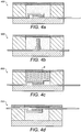
- FIGS 4a to 4d illustrate examples of the fourth to seventh embodiments of the present invention, respectively.
- the actuator 400 shown in Figure 4a has the semiconductor element 6 oriented parallel to and adjacent the base 1 c.
- the actuator 500 has the semiconductor element 6 oriented perpendicular to and adjacent the base 1 c.
- the actuator 600 is similar to the actuator 400 and further comprises a radiator element for dissipating heat from the semiconductor element 6 into a the cavity 2.
- the actuator 700 shown in Figure 4d shows the semiconductor element oriented parallel to and adjacent the diaphragm 4.
- the working medium 3 is preferably a blend of two different paraffin waxes wherein one has a higher molecular weight than the other.
- the higher molecular weight wax causes expansion and the lower molecular weight wax fills between a crystalline structure of the higher molecular weight wax.
- Both waxes are preferably substantially pure so as to ensure a sharp a melting point as possible. It will be appreciated by those skilled in the art that other types of wax such as thermostat waxes and Polyethylene glycols could be used as the working medium 3 in the actuator of the present invention.
- An example of a preferred wax composition comprises approximately 60% hexatriacontane and approximately 40% paraffin wax.
- FIG. 5 illustrates the actuator 100 in combination with a gearing assembly 150.
- the function of the gearing system is to amplify either the linear displacement of the diaphragm 4, or increase the effective volume displacement resulting from the deflection of the diaphragm 4.
- a gearing assembly 150 shown in Figure 5 is of a type for amplifying the volume displacement.
- the gearing assembly 150 comprises a gearing piston 151, and a gearing diaphragm 152 connected to a gearing frame 153.
- the gearing frame 153 is fixed to a body 154 of the gearing assembly 150.
- the piston 151 is connected, or positioned in contact with, the actuator diaphragm 4. Movement of the piston 151 is restrained within the body 154 such that the piston 151 moves upwardly and downwardly with the diaphragm 4. The other end of the piston 151 is positioned just beneath the diaphragm 152 such that deflection of the actuator diaphragm 154 causes the piston 151 to move thus deflecting the gearing diaphragm 152.
- the gearing diaphragm 152 is larger than the actuator diaphragm 4 and due to the arrangement of the diaphragms 4, 152 and piston 151, the volume displacement of the gearing diaphragm 152 is significantly greater than the volume displacement of the actuator diaphragm 4.
- the force per unit area exerted by displacement of the gearing diaphragm 152 is less than the force per unit area exerted by deflection of the actuator diaphragm 4 due to the gearing assembly, this is not critical where the working medium 3 of the actuator is wax due to the high "energy density" of the wax actuator which enables the gearing diaphragm 152 to apply a sufficient force per unit area for many of the applications envisaged for the geared actuator.
- the gearing assembly 150 has a small number of parts that are easy to manufacture and assemble and so the geared actuator may be produced at low cost and reliably to achieve a disposable product that provides good performance.
- the piston 151, frame 153 and body 154 are preferably of plastics material and the diaphragm 152 is preferably of flexible, resilient elastomeric material, for example rubber. Other materials for the piston, frame , body and diaphragm may be used in the alternative, such as metal, ceramic, glass and silicon as will be appreciated by those skilled in the art.
- the frame 153 could be integrally formed with the diaphragm 152.
- a return force may be required to assist in returning the actuator to its initial position, i.e. that as before melting of the working medium 3.
- the return force may be provided by a spring or other suitable known means to bias the gearing piston 151 towards the actuator 100.
- the return force is provided by tension in the gearing diaphragm 152 and/or the actuator diaphragm 4. Where this is found to be insufficient, a tension spring connected at one end to the body 154 and at its other end to a flange of the piston 151 may be provided, for example.
- the actuator 100 is provided without the gearing assembly 150, it may be preferable to provide means for biasing the actuator diaphragm 4 towards the cavity 2 for the same reason.
- the absence of such a return force acting on the diaphragm 4 directly, or indirectly, may result in non-uniform cooling of the working medium 3 following heating. This will then have a knock-on effect during any subsequent heating operation leading to unreliable operation.
- the gearing assembly 150 is particularly suitable for use in a geared micro-actuator assembly due to the relatively low profile of the gearing assembly 150. Whilst the gearing assembly 150 is of a volume amplifier type, it will be appreciated by those skilled in the art that a linear displacement amplifier type gearing assembly may be constructed using a system of levers, or gears and pulleys.
- the actuator, or the geared actuator, of the present invention has many possible uses, such as in valves and pumps for medical, industrial or environmental applications, and in a range of sizes from small/medium scale devices to micro-systems.
- FIG. 6 An example of an application of the geared micro-actuator of Figure 5 is as a micro-pump, as shown in Figure 6 .
- the micro-pump 170 has a fluid inlet 171 leading to an inlet valve 172.
- Operation of the actuator 100 having the gearing assembly 150 causes a change in volume of a pumping chamber 173.
- the inlet valve 172 opens and fluid flows from the inlet 171 through the inlet valve 172 to fill the pumping chamber 173.
- the pumping chamber 173 is full, operation of the geared actuator 100,150 to reduce the volume of the pumping chamber 173 forces the fluid along conduit 174 to outlet valve 175. Since the fluid passing through the conduit 174 is under pressure from the geared actuator 100,150, the outlet valve 175 opens and fluid exits the pump via outlet 176.
- the inlet and outlet valves 172,175 are one-way valves such that upon a decrease in the volume of the pumping chamber 173 fluid therein does not pass through the inlet valve 172 to the inlet 171 and only passes along the conduit 174. Also, the outlet valve 175 closes when the pressure of the fluid in the conduit 174 decreases below a predetermined value. Repeated operation of the geared actuator 100,150 causes fluid to be pumped from the inlet 171 to the outlet 176.
- the micro-pump 170 described with reference to Figure 6 finds particular use in a micro-infusion system for the delivery of therapeutic products into a human or animal body.
- the infusion system is shown in Figure 7 and includes a pressurized reservoir 191 of therapeutic product 192.
- the therapeutic product 192 is pressurized within the reservoir by application of a force, indicated by 193, on a plunger 194 movable within the reservoir cavity.
- An outlet 195 of the reservoir is connected to the inlet 171 of the micro pump 170.
- Means for fluidically coupling the micro-pump 170 to a human or animal body to which the therapeutic product is to be delivered is connected at one end to the patient, and at the other end to the outlet 176 of the micro pump 170. This means may be a cannular or other similar device.
- the actuator is preferably controlled by an electronics module (not shown) that works in co-operation with at least one flow rate indicator to ensure programmed delivery of the therapeutic product with a high degree of accuracy.
Landscapes
- Engineering & Computer Science (AREA)
- Mechanical Engineering (AREA)
- General Engineering & Computer Science (AREA)
- Chemical & Material Sciences (AREA)
- Combustion & Propulsion (AREA)
- Analytical Chemistry (AREA)
- Computer Hardware Design (AREA)
- Microelectronics & Electronic Packaging (AREA)
- Reciprocating Pumps (AREA)
- Micromachines (AREA)
Claims (13)
- Micro-actionneur comprenant :une cavité contenant un milieu de travail qui s'expanse de manière réversible lorsqu'il subit un changement de phase d'un état solide à un état liquide ;une membrane disposée de manière adjacente à la cavité de sorte que l'expansion et la contraction du milieu de travail expansible amène la membrane à fléchir; et,un élément semi-conducteur disposé dans la cavité,dans lequel l'élément semi-conducteur est immergé dans le milieu de travail de manière adjacente à la membrane et est conçu pour chauffer le milieu de travail pour l'amener à subir le changement de phase dans l'état liquide.
- Actionneur selon la revendication 1, dans lequel seule une partie du milieu de travail dans la cavité subit le changement de phase pendant un cycle d'actionnement.
- Actionneur selon la revendication 1 ou la revendication 2, dans lequel le milieu de travail comprend de la cire, qui peut comprendre un mélange de deux cires différentes, une ayant un poids moléculaire plus élevé que l'autre.
- Actionneur selon la revendication 3, dans lequel le milieu de travail comprend environ 60 % d'hexatriacontane et environ 40 % de cire de paraffine.
- Actionneur selon l'une quelconque des revendications précédentes, dans lequel des connexions électriques à l'élément semi-conducteur sont disposées au moins partiellement à l'intérieur de la cavité et de manière adjacente à la membrane, le milieu de travail remplissant un espace entre la membrane et les connexions électriques.
- Actionneur selon l'une quelconque des revendications précédentes, dans lequel la cavité est liée par un corps d'actionneur et la membrane.
- Actionneur selon l'une quelconque des revendications précédentes, comprenant en outre un système de transmission pour amplifier un déplacement linéaire ou de volume de la membrane.
- Actionneur selon la revendication 7, dans lequel le système de transmission comprend un piston de transmission conçu pour faire fléchir une membrane de transmission, plus grande que la membrane d'actionneur.
- Pompe comprenant l'actionneur selon l'une quelconque des revendications précédentes.
- Pompe selon la revendication 9, pour pomper un produit thérapeutique liquide, comprenant une chambre de pompage ayant une entrée et une sortie, dans laquelle un volume de la chambre de pompage est amené à changer par actionnement de l'actionneur, la pompe comprenant en outre une soupape d'entrée et une soupape de sortie.
- Pompe selon la revendication 10, dans laquelle la soupape de sortie a une pression d'activation plus élevée que la soupape d'entrée.
- Pompe selon l'une quelconque des revendications 9 à 11, dans laquelle le volume de la chambre de pompage est inférieur à environ 100 ni.
- Système de perfusion comprenant la pompe selon l'une quelconque des revendications 10 à 12.
Applications Claiming Priority (2)
| Application Number | Priority Date | Filing Date | Title |
|---|---|---|---|
| GB0621344A GB2443261B (en) | 2006-10-26 | 2006-10-26 | Wax micro actuator |
| PCT/GB2007/004073 WO2008050128A1 (fr) | 2006-10-26 | 2007-10-25 | Micro-actionneur à cire |
Publications (2)
| Publication Number | Publication Date |
|---|---|
| EP2076675A1 EP2076675A1 (fr) | 2009-07-08 |
| EP2076675B1 true EP2076675B1 (fr) | 2017-07-26 |
Family
ID=37546046
Family Applications (1)
| Application Number | Title | Priority Date | Filing Date |
|---|---|---|---|
| EP07824317.7A Active EP2076675B1 (fr) | 2006-10-26 | 2007-10-25 | Micro-actionneur à cire |
Country Status (10)
| Country | Link |
|---|---|
| US (1) | US8784403B2 (fr) |
| EP (1) | EP2076675B1 (fr) |
| JP (1) | JP4945640B2 (fr) |
| KR (1) | KR101463187B1 (fr) |
| CN (1) | CN101583797B (fr) |
| AU (1) | AU2007310635B2 (fr) |
| CA (1) | CA2667529C (fr) |
| DK (1) | DK2076675T3 (fr) |
| GB (2) | GB2456681B (fr) |
| WO (1) | WO2008050128A1 (fr) |
Families Citing this family (163)
| Publication number | Priority date | Publication date | Assignee | Title |
|---|---|---|---|---|
| GB2456681B (en) | 2006-10-26 | 2009-11-11 | Starbridge Systems Ltd | Pump |
| GB2443260C (en) | 2006-10-26 | 2017-11-29 | Cellnovo Ltd | Micro-valve |
| US7655004B2 (en) | 2007-02-15 | 2010-02-02 | Ethicon Endo-Surgery, Inc. | Electroporation ablation apparatus, system, and method |
| US8075572B2 (en) | 2007-04-26 | 2011-12-13 | Ethicon Endo-Surgery, Inc. | Surgical suturing apparatus |
| US8100922B2 (en) | 2007-04-27 | 2012-01-24 | Ethicon Endo-Surgery, Inc. | Curved needle suturing tool |
| US8417311B2 (en) | 2008-09-12 | 2013-04-09 | Optiscan Biomedical Corporation | Fluid component analysis system and method for glucose monitoring and control |
| US7751907B2 (en) | 2007-05-24 | 2010-07-06 | Smiths Medical Asd, Inc. | Expert system for insulin pump therapy |
| US8568410B2 (en) | 2007-08-31 | 2013-10-29 | Ethicon Endo-Surgery, Inc. | Electrical ablation surgical instruments |
| US8262655B2 (en) | 2007-11-21 | 2012-09-11 | Ethicon Endo-Surgery, Inc. | Bipolar forceps |
| US8579897B2 (en) | 2007-11-21 | 2013-11-12 | Ethicon Endo-Surgery, Inc. | Bipolar forceps |
| EP3868284A1 (fr) | 2007-10-10 | 2021-08-25 | Optiscan Biomedical Corporation | Système d'analyse de composant de fluide et procédé pour contrôler et réguler le glucose |
| US8480657B2 (en) | 2007-10-31 | 2013-07-09 | Ethicon Endo-Surgery, Inc. | Detachable distal overtube section and methods for forming a sealable opening in the wall of an organ |
| US20090112059A1 (en) | 2007-10-31 | 2009-04-30 | Nobis Rudolph H | Apparatus and methods for closing a gastrotomy |
| US8986253B2 (en) | 2008-01-25 | 2015-03-24 | Tandem Diabetes Care, Inc. | Two chamber pumps and related methods |
| US8262680B2 (en) | 2008-03-10 | 2012-09-11 | Ethicon Endo-Surgery, Inc. | Anastomotic device |
| US8652150B2 (en) | 2008-05-30 | 2014-02-18 | Ethicon Endo-Surgery, Inc. | Multifunction surgical device |
| US8771260B2 (en) | 2008-05-30 | 2014-07-08 | Ethicon Endo-Surgery, Inc. | Actuating and articulating surgical device |
| US8317806B2 (en) | 2008-05-30 | 2012-11-27 | Ethicon Endo-Surgery, Inc. | Endoscopic suturing tension controlling and indication devices |
| US8679003B2 (en) | 2008-05-30 | 2014-03-25 | Ethicon Endo-Surgery, Inc. | Surgical device and endoscope including same |
| US8070759B2 (en) | 2008-05-30 | 2011-12-06 | Ethicon Endo-Surgery, Inc. | Surgical fastening device |
| US8114072B2 (en) | 2008-05-30 | 2012-02-14 | Ethicon Endo-Surgery, Inc. | Electrical ablation device |
| US8906035B2 (en) | 2008-06-04 | 2014-12-09 | Ethicon Endo-Surgery, Inc. | Endoscopic drop off bag |
| US8403926B2 (en) | 2008-06-05 | 2013-03-26 | Ethicon Endo-Surgery, Inc. | Manually articulating devices |
| US8361112B2 (en) | 2008-06-27 | 2013-01-29 | Ethicon Endo-Surgery, Inc. | Surgical suture arrangement |
| US8888792B2 (en) | 2008-07-14 | 2014-11-18 | Ethicon Endo-Surgery, Inc. | Tissue apposition clip application devices and methods |
| US8262563B2 (en) | 2008-07-14 | 2012-09-11 | Ethicon Endo-Surgery, Inc. | Endoscopic translumenal articulatable steerable overtube |
| US8211125B2 (en) | 2008-08-15 | 2012-07-03 | Ethicon Endo-Surgery, Inc. | Sterile appliance delivery device for endoscopic procedures |
| US7959598B2 (en) | 2008-08-20 | 2011-06-14 | Asante Solutions, Inc. | Infusion pump systems and methods |
| US8529563B2 (en) | 2008-08-25 | 2013-09-10 | Ethicon Endo-Surgery, Inc. | Electrical ablation devices |
| US8241204B2 (en) | 2008-08-29 | 2012-08-14 | Ethicon Endo-Surgery, Inc. | Articulating end cap |
| US8480689B2 (en) | 2008-09-02 | 2013-07-09 | Ethicon Endo-Surgery, Inc. | Suturing device |
| US8409200B2 (en) | 2008-09-03 | 2013-04-02 | Ethicon Endo-Surgery, Inc. | Surgical grasping device |
| US8114119B2 (en) | 2008-09-09 | 2012-02-14 | Ethicon Endo-Surgery, Inc. | Surgical grasping device |
| US8337394B2 (en) | 2008-10-01 | 2012-12-25 | Ethicon Endo-Surgery, Inc. | Overtube with expandable tip |
| US8157834B2 (en) | 2008-11-25 | 2012-04-17 | Ethicon Endo-Surgery, Inc. | Rotational coupling device for surgical instrument with flexible actuators |
| US8172772B2 (en) | 2008-12-11 | 2012-05-08 | Ethicon Endo-Surgery, Inc. | Specimen retrieval device |
| US8828031B2 (en) | 2009-01-12 | 2014-09-09 | Ethicon Endo-Surgery, Inc. | Apparatus for forming an anastomosis |
| US8361066B2 (en) | 2009-01-12 | 2013-01-29 | Ethicon Endo-Surgery, Inc. | Electrical ablation devices |
| US8252057B2 (en) | 2009-01-30 | 2012-08-28 | Ethicon Endo-Surgery, Inc. | Surgical access device |
| US9226772B2 (en) | 2009-01-30 | 2016-01-05 | Ethicon Endo-Surgery, Inc. | Surgical device |
| US8037591B2 (en) | 2009-02-02 | 2011-10-18 | Ethicon Endo-Surgery, Inc. | Surgical scissors |
| US9222819B2 (en) * | 2009-02-20 | 2015-12-29 | University Of Southern California | Tracking and controlling fluid delivery from chamber |
| EP2724739B1 (fr) | 2009-07-30 | 2015-07-01 | Tandem Diabetes Care, Inc. | Système de pompe à perfusion ambulatoire |
| US20110098704A1 (en) | 2009-10-28 | 2011-04-28 | Ethicon Endo-Surgery, Inc. | Electrical ablation devices |
| US8608652B2 (en) | 2009-11-05 | 2013-12-17 | Ethicon Endo-Surgery, Inc. | Vaginal entry surgical devices, kit, system, and method |
| US8353487B2 (en) | 2009-12-17 | 2013-01-15 | Ethicon Endo-Surgery, Inc. | User interface support devices for endoscopic surgical instruments |
| US8496574B2 (en) | 2009-12-17 | 2013-07-30 | Ethicon Endo-Surgery, Inc. | Selectively positionable camera for surgical guide tube assembly |
| US9028483B2 (en) | 2009-12-18 | 2015-05-12 | Ethicon Endo-Surgery, Inc. | Surgical instrument comprising an electrode |
| US8506564B2 (en) | 2009-12-18 | 2013-08-13 | Ethicon Endo-Surgery, Inc. | Surgical instrument comprising an electrode |
| US9005198B2 (en) | 2010-01-29 | 2015-04-14 | Ethicon Endo-Surgery, Inc. | Surgical instrument comprising an electrode |
| DE102010061909A1 (de) | 2010-11-24 | 2012-05-24 | Fraunhofer-Gesellschaft zur Förderung der angewandten Forschung e.V. | Fluidischer Aktor mit verformbarer Verschlussanordnung und langer Lagerfähigkeit |
| US10092291B2 (en) | 2011-01-25 | 2018-10-09 | Ethicon Endo-Surgery, Inc. | Surgical instrument with selectively rigidizable features |
| US9314620B2 (en) | 2011-02-28 | 2016-04-19 | Ethicon Endo-Surgery, Inc. | Electrical ablation devices and methods |
| US9254169B2 (en) | 2011-02-28 | 2016-02-09 | Ethicon Endo-Surgery, Inc. | Electrical ablation devices and methods |
| US9233241B2 (en) | 2011-02-28 | 2016-01-12 | Ethicon Endo-Surgery, Inc. | Electrical ablation devices and methods |
| WO2012125785A1 (fr) | 2011-03-17 | 2012-09-20 | Ethicon Endo-Surgery, Inc. | Dispositif chirurgical portatif de manipulation d'un ensemble à aimants interne dans le corps d'un patient |
| CN102331473A (zh) * | 2011-09-09 | 2012-01-25 | 李彤 | 相变驱动流体的输液泵 |
| CN102410187A (zh) * | 2011-09-21 | 2012-04-11 | 杭州普普科技有限公司 | 一种实现液体流量输出的方法、相变动力装置与恒流泵 |
| US8986199B2 (en) | 2012-02-17 | 2015-03-24 | Ethicon Endo-Surgery, Inc. | Apparatus and methods for cleaning the lens of an endoscope |
| RS65875B1 (sr) | 2012-03-30 | 2024-09-30 | Insulet Corp | Sredstvo za isporučivanje tečnosti sa alatom za transkutani pristup, mehanizmom za inserciju i praćenje nivoa glukoze u krvi za istovremenu upotrebu |
| US9427255B2 (en) | 2012-05-14 | 2016-08-30 | Ethicon Endo-Surgery, Inc. | Apparatus for introducing a steerable camera assembly into a patient |
| US9180242B2 (en) | 2012-05-17 | 2015-11-10 | Tandem Diabetes Care, Inc. | Methods and devices for multiple fluid transfer |
| US9078662B2 (en) | 2012-07-03 | 2015-07-14 | Ethicon Endo-Surgery, Inc. | Endoscopic cap electrode and method for using the same |
| US9545290B2 (en) | 2012-07-30 | 2017-01-17 | Ethicon Endo-Surgery, Inc. | Needle probe guide |
| US10314649B2 (en) | 2012-08-02 | 2019-06-11 | Ethicon Endo-Surgery, Inc. | Flexible expandable electrode and method of intraluminal delivery of pulsed power |
| US9572623B2 (en) | 2012-08-02 | 2017-02-21 | Ethicon Endo-Surgery, Inc. | Reusable electrode and disposable sheath |
| US9277957B2 (en) | 2012-08-15 | 2016-03-08 | Ethicon Endo-Surgery, Inc. | Electrosurgical devices and methods |
| US10047730B2 (en) | 2012-10-12 | 2018-08-14 | Woodward, Inc. | High-temperature thermal actuator utilizing phase change material |
| US10098527B2 (en) | 2013-02-27 | 2018-10-16 | Ethidcon Endo-Surgery, Inc. | System for performing a minimally invasive surgical procedure |
| US9173998B2 (en) | 2013-03-14 | 2015-11-03 | Tandem Diabetes Care, Inc. | System and method for detecting occlusions in an infusion pump |
| DE102013207193A1 (de) * | 2013-04-22 | 2014-10-23 | Robert Bosch Gmbh | Mikrohydraulisches System, insbesondere zum Einsatz in planaren Mikrofluidiklaboren |
| US9561324B2 (en) | 2013-07-19 | 2017-02-07 | Bigfoot Biomedical, Inc. | Infusion pump system and method |
| GB2525149A (en) | 2014-01-30 | 2015-10-21 | Cellnovo Ltd | Therapeutic product delivery device |
| GB2525150A (en) | 2014-01-30 | 2015-10-21 | Cellnovo Ltd | Therapeutic product delivery device |
| GB2524717A (en) | 2014-01-30 | 2015-10-07 | Cellnovo Ltd | Managing communications to and from a handset device controlling a therapeutic product delivery device |
| GB2523544A (en) | 2014-01-30 | 2015-09-02 | Cellnovo Ltd | Handset device |
| GB2584029B (en) * | 2014-01-30 | 2021-02-17 | Insulet Netherlands B V | Actuator and actuation method |
| GB2523989B (en) | 2014-01-30 | 2020-07-29 | Insulet Netherlands B V | Therapeutic product delivery system and method of pairing |
| GB2525838B (en) * | 2014-01-30 | 2020-12-30 | Insulet Netherlands B V | Actuator and actuation method |
| US10441717B2 (en) | 2014-04-15 | 2019-10-15 | Insulet Corporation | Monitoring a physiological parameter associated with tissue of a host to confirm delivery of medication |
| US10737024B2 (en) | 2015-02-18 | 2020-08-11 | Insulet Corporation | Fluid delivery and infusion devices, and methods of use thereof |
| US10716896B2 (en) | 2015-11-24 | 2020-07-21 | Insulet Corporation | Wearable automated medication delivery system |
| US10413665B2 (en) | 2015-11-25 | 2019-09-17 | Insulet Corporation | Wearable medication delivery device |
| WO2017123525A1 (fr) | 2016-01-13 | 2017-07-20 | Bigfoot Biomedical, Inc. | Interface utilisateur pour système de gestion du diabète |
| US10610643B2 (en) | 2016-01-14 | 2020-04-07 | Bigfoot Biomedical, Inc. | Occlusion resolution in medication delivery devices, systems, and methods |
| US10780223B2 (en) | 2016-01-14 | 2020-09-22 | Bigfoot Biomedical, Inc. | Adjusting insulin delivery rates |
| US12383166B2 (en) | 2016-05-23 | 2025-08-12 | Insulet Corporation | Insulin delivery system and methods with risk-based set points |
| WO2017205816A1 (fr) | 2016-05-26 | 2017-11-30 | Insulet Corporation | Dispositif d'administration d'un médicament unidose |
| WO2018035051A1 (fr) | 2016-08-14 | 2018-02-22 | Insulet Corporation | Dispositif d'administration de médicament avec détection de position du piston |
| US10765807B2 (en) | 2016-09-23 | 2020-09-08 | Insulet Corporation | Fluid delivery device with sensor |
| WO2018067645A1 (fr) | 2016-10-07 | 2018-04-12 | Insulet Corporation | Système d'administration à plusieurs étages |
| US10780217B2 (en) | 2016-11-10 | 2020-09-22 | Insulet Corporation | Ratchet drive for on body delivery system |
| ES2985905T3 (es) | 2016-11-22 | 2024-11-07 | Lts Device Tech Ltd | Aparato para suministrar una sustancia terapéutica |
| US11096624B2 (en) | 2016-12-12 | 2021-08-24 | Bigfoot Biomedical, Inc. | Alarms and alerts for medication delivery devices and systems |
| EP3568862B1 (fr) | 2017-01-13 | 2026-03-18 | Insulet Corporation | Système et procédé d'ajustement d'administration d'insuline |
| WO2018132765A1 (fr) | 2017-01-13 | 2018-07-19 | Mazlish Bryan | Procédés, systèmes et dispositifs d'administration d'insuline |
| EP3568860B1 (fr) | 2017-01-13 | 2025-12-10 | Insulet Corporation | Méthodes, systèmes et dispositifs d'administration d'insuline |
| US10583250B2 (en) | 2017-01-13 | 2020-03-10 | Bigfoot Biomedical, Inc. | System and method for adjusting insulin delivery |
| US10500334B2 (en) | 2017-01-13 | 2019-12-10 | Bigfoot Biomedical, Inc. | System and method for adjusting insulin delivery |
| US10758675B2 (en) | 2017-01-13 | 2020-09-01 | Bigfoot Biomedical, Inc. | System and method for adjusting insulin delivery |
| WO2018136699A1 (fr) | 2017-01-19 | 2018-07-26 | Insulet Corporation | Réduction du volume de rétention de cartouche |
| US11045603B2 (en) | 2017-02-22 | 2021-06-29 | Insulet Corporation | Needle insertion mechanisms for drug containers |
| US10695485B2 (en) | 2017-03-07 | 2020-06-30 | Insulet Corporation | Very high volume user filled drug delivery device |
| US10973978B2 (en) | 2017-08-03 | 2021-04-13 | Insulet Corporation | Fluid flow regulation arrangements for drug delivery devices |
| WO2019028342A1 (fr) | 2017-08-03 | 2019-02-07 | Insulet Corporation | Micro-pompe à piston |
| US11786668B2 (en) | 2017-09-25 | 2023-10-17 | Insulet Corporation | Drug delivery devices, systems, and methods with force transfer elements |
| EP3687600B1 (fr) | 2017-09-26 | 2022-04-27 | Insulet Corporation | Module de mécanisme d'aiguille pour dispositif d'administration de médicament |
| US11147931B2 (en) | 2017-11-17 | 2021-10-19 | Insulet Corporation | Drug delivery device with air and backflow elimination |
| USD928199S1 (en) | 2018-04-02 | 2021-08-17 | Bigfoot Biomedical, Inc. | Medication delivery device with icons |
| CN118750687A (zh) | 2018-05-04 | 2024-10-11 | 英赛罗公司 | 基于控制算法的药物输送系统的安全约束 |
| US12562251B1 (en) | 2018-05-09 | 2026-02-24 | Bigfoot Biomedical, Inc. | Computing architecture for assuring the provenance of medication therapy related parameters, and related systems, methods and devices |
| US10874803B2 (en) | 2018-05-31 | 2020-12-29 | Insulet Corporation | Drug cartridge with drive system |
| EP3801682A1 (fr) | 2018-06-06 | 2021-04-14 | Insulet Corporation | Pompe à navette linéaire pour l'administration de médicament |
| US11241532B2 (en) | 2018-08-29 | 2022-02-08 | Insulet Corporation | Drug delivery system with sensor having optimized communication and infusion site |
| JP2022501139A (ja) | 2018-09-28 | 2022-01-06 | インスレット コーポレイション | 人工膵臓システム用活動モード |
| US11357909B2 (en) | 2018-10-05 | 2022-06-14 | Eitan Medical Ltd. | Triggering sequence |
| US11565039B2 (en) | 2018-10-11 | 2023-01-31 | Insulet Corporation | Event detection for drug delivery system |
| US11446435B2 (en) | 2018-11-28 | 2022-09-20 | Insulet Corporation | Drug delivery shuttle pump system and valve assembly |
| USD920343S1 (en) | 2019-01-09 | 2021-05-25 | Bigfoot Biomedical, Inc. | Display screen or portion thereof with graphical user interface associated with insulin delivery |
| US11187345B2 (en) | 2019-02-27 | 2021-11-30 | Hamilton Sundstrand Corporation | Paraffin actuated diaphragm valve |
| US11801344B2 (en) | 2019-09-13 | 2023-10-31 | Insulet Corporation | Blood glucose rate of change modulation of meal and correction insulin bolus quantity |
| US11935637B2 (en) | 2019-09-27 | 2024-03-19 | Insulet Corporation | Onboarding and total daily insulin adaptivity |
| US11369735B2 (en) | 2019-11-05 | 2022-06-28 | Insulet Corporation | Component positioning of a linear shuttle pump |
| GB2591073A (en) | 2019-11-25 | 2021-07-21 | Nicoventures Trading Ltd | Aerosolisable material for insertion into an aerosol provision device |
| US11957875B2 (en) | 2019-12-06 | 2024-04-16 | Insulet Corporation | Techniques and devices providing adaptivity and personalization in diabetes treatment |
| US11833329B2 (en) | 2019-12-20 | 2023-12-05 | Insulet Corporation | Techniques for improved automatic drug delivery performance using delivery tendencies from past delivery history and use patterns |
| JP7512395B2 (ja) | 2020-01-06 | 2024-07-08 | インスレット コーポレイション | 持続する残差に基づく食事および/または運動行為の予測 |
| EP4100958A1 (fr) | 2020-02-03 | 2022-12-14 | Insulet Corporation | Utilisation d'une logique floue pour prédire un comportement d'utilisateur affectant la glycémie |
| US11551802B2 (en) | 2020-02-11 | 2023-01-10 | Insulet Corporation | Early meal detection and calorie intake detection |
| US11547800B2 (en) | 2020-02-12 | 2023-01-10 | Insulet Corporation | User parameter dependent cost function for personalized reduction of hypoglycemia and/or hyperglycemia in a closed loop artificial pancreas system |
| US11986630B2 (en) | 2020-02-12 | 2024-05-21 | Insulet Corporation | Dual hormone delivery system for reducing impending hypoglycemia and/or hyperglycemia risk |
| US11324889B2 (en) | 2020-02-14 | 2022-05-10 | Insulet Corporation | Compensation for missing readings from a glucose monitor in an automated insulin delivery system |
| US12495994B2 (en) | 2020-02-20 | 2025-12-16 | Insulet Corporation | Meal bolus subcategories in model based insulin therapy |
| US11607493B2 (en) | 2020-04-06 | 2023-03-21 | Insulet Corporation | Initial total daily insulin setting for user onboarding |
| US12121700B2 (en) | 2020-07-22 | 2024-10-22 | Insulet Corporation | Open-loop insulin delivery basal parameters based on insulin delivery records |
| US11684716B2 (en) | 2020-07-31 | 2023-06-27 | Insulet Corporation | Techniques to reduce risk of occlusions in drug delivery systems |
| US12569619B2 (en) | 2020-09-21 | 2026-03-10 | Insulet Corporation | Techniques for determining automated insulin delivery dosages |
| JP7409519B2 (ja) * | 2020-09-30 | 2024-01-09 | 株式会社村田製作所 | 流体制御装置 |
| US12128215B2 (en) | 2020-09-30 | 2024-10-29 | Insulet Corporation | Drug delivery device with integrated optical-based glucose monitor |
| EP4221588A1 (fr) | 2020-09-30 | 2023-08-09 | Insulet Corporation | Communications sans fil sécurisées entre un dispositif de surveillance de glucose et d'autres dispositifs |
| WO2022072823A2 (fr) | 2020-10-02 | 2022-04-07 | Insulet Corporation | Dispositif de distribution de liquide comportant de multiples éléments pénétrants |
| EP4262921A1 (fr) | 2020-12-18 | 2023-10-25 | Insulet Corporation | Patin adhésif à bobine métallique pour fixer un dispositif médical sur le corps |
| US12377208B2 (en) | 2021-01-08 | 2025-08-05 | Insulet Corporation | Single actuated precision dose intermediate pumping chamber |
| US12440617B2 (en) | 2021-01-11 | 2025-10-14 | Insulet Corporation | Linear activated drug dosing pump system |
| US11160925B1 (en) | 2021-01-29 | 2021-11-02 | Insulet Corporation | Automatic drug delivery system for delivery of a GLP-1 therapeutic |
| US11904140B2 (en) | 2021-03-10 | 2024-02-20 | Insulet Corporation | Adaptable asymmetric medicament cost component in a control system for medicament delivery |
| US12431229B2 (en) | 2021-03-10 | 2025-09-30 | Insulet Corporation | Medicament delivery device with an adjustable and piecewise analyte level cost component to address persistent positive analyte level excursions |
| EP4304676B1 (fr) | 2021-03-12 | 2026-04-22 | Insulet Corporation | Mécanismes d'entraînement améliorés pour les pompes volumétriques |
| US12592306B2 (en) | 2021-04-28 | 2026-03-31 | Insulet Corporation | Devices and methods for initialization of drug delivery devices using measured analyte sensor information |
| US12594376B2 (en) | 2021-05-21 | 2026-04-07 | Insulet Corporation | Compact positive displacement pump for wearable drug delivery device |
| US12496398B2 (en) | 2021-05-28 | 2025-12-16 | Insulet Corporation | Threshold based automatic glucose control response |
| EP4346945A1 (fr) | 2021-05-28 | 2024-04-10 | Insulet Corporation | Capteurs d'état à base de ressort |
| US12406760B2 (en) | 2021-06-07 | 2025-09-02 | Insulet Corporation | Exercise safety prediction based on physiological conditions |
| US12514980B2 (en) | 2021-06-30 | 2026-01-06 | Insulet Corporation | Adjustment of medicament delivery by a medicament delivery device based on menstrual cycle phase |
| US12521486B2 (en) | 2021-07-16 | 2026-01-13 | Insulet Corporation | Method for modification of insulin delivery during pregnancy in automatic insulin delivery systems |
| EP4409581A1 (fr) | 2021-09-27 | 2024-08-07 | Insulet Corporation | Techniques permettant l'adaptation de paramètres dans des systèmes d'aide par entrée d'utilisateur |
| US11439754B1 (en) | 2021-12-01 | 2022-09-13 | Insulet Corporation | Optimizing embedded formulations for drug delivery |
| EP4243030A1 (fr) | 2022-03-09 | 2023-09-13 | Insulet Corporation | Ajustement de paramètres d'administration de médicament dans un mode d'administration de médicament en boucle ouverte |
| CN114915094B (zh) * | 2022-05-23 | 2024-11-01 | 大连海事大学 | 一种基于石蜡相变驱动的深海旋转式驱动器 |
| CN115026793B (zh) * | 2022-05-23 | 2024-08-09 | 大连海事大学 | 一种基于石蜡相变的深海直线式驱动器 |
| KR20250044385A (ko) | 2022-08-04 | 2025-03-31 | 인슐렛 코포레이션 | 이중 저장조 및 고정 유체 포트를 갖는 펌프 기구 |
| CN120457493A (zh) | 2023-01-06 | 2025-08-08 | 英赛罗公司 | 自动或手动启动的随餐推注输送及随后的自动安全约束放宽 |
| CN119716121A (zh) * | 2025-01-03 | 2025-03-28 | 湖南格致分析仪器有限公司 | 一种基于质谱仪的优化处理方法 |
Family Cites Families (34)
| Publication number | Priority date | Publication date | Assignee | Title |
|---|---|---|---|---|
| GB875034A (en) | 1957-07-01 | 1961-08-16 | Renault | Improvements in or relating to valves for fluids under pressure |
| US3176712A (en) * | 1961-10-03 | 1965-04-06 | Ramsden Clement | Non-return valve |
| US3297260A (en) * | 1964-09-21 | 1967-01-10 | Conrad R Barlow | Nozzle and valve assembly |
| US3505809A (en) * | 1968-05-20 | 1970-04-14 | Thermal Hydraulics Corp | Thermal motor |
| US3686857A (en) * | 1971-08-03 | 1972-08-29 | Texas Instruments Inc | Thermal actuator |
| US4210173A (en) * | 1976-12-06 | 1980-07-01 | American Hospital Supply Corporation | Syringe pumping system with valves |
| US4152098A (en) * | 1977-01-03 | 1979-05-01 | Clark Ivan P | Micropump |
| DE2749251C3 (de) * | 1977-11-03 | 1981-10-08 | Danfoss A/S, 6430 Nordborg | Regelbare Heizvorrichtung für kleine Massen, insbesondere das Ausdehnungsmittel in Wärmestellvorrichtungen |
| US4265601A (en) * | 1978-09-05 | 1981-05-05 | Harold Mandroian | Three valve precision pump apparatus with head pressure flowthrough protection |
| FR2507637B1 (fr) * | 1981-06-16 | 1986-09-26 | Libero Elettrotecnica | Dispositif d'actionnement thermoelectrique, notamment pour activer des distributeurs de detergents et/ou d'agents de brillantage dans des machines a laver |
| US4714462A (en) * | 1986-02-03 | 1987-12-22 | Intermedics Infusaid, Inc. | Positive pressure programmable infusion pump |
| US4858619A (en) * | 1987-06-29 | 1989-08-22 | Toth Marie A | Intracranial pressure monitoring system |
| US5020325A (en) * | 1990-02-13 | 1991-06-04 | Procedes Vernet | Heat motor |
| JPH04274719A (ja) * | 1991-03-01 | 1992-09-30 | Ntc Kogyo Kk | ワツクスサーモエレメント型のサーモセンサ |
| JPH0698988A (ja) | 1992-09-21 | 1994-04-12 | Sanyo Electric Co Ltd | ドラム式洗濯乾燥機 |
| JPH06159228A (ja) * | 1992-11-26 | 1994-06-07 | Japan Aviation Electron Ind Ltd | アクチュエータ |
| DE4241943C2 (de) * | 1992-12-11 | 1994-12-01 | Busak & Luyken Gmbh & Co | Verschlußmittel und Dichtungsventil für Behälteröffnungen |
| JPH06249130A (ja) * | 1993-02-25 | 1994-09-06 | Suzuki Motor Corp | サーモアクチュエータ装置 |
| US5520661A (en) * | 1994-07-25 | 1996-05-28 | Baxter International Inc. | Fluid flow regulator |
| FR2731475B1 (fr) * | 1995-03-07 | 1997-05-30 | Thomson Dauphinoise | Dispositif de montage d'un composant electrique de chauffage et/ou de refroidissement sur un verin thermique |
| DE19723648C1 (de) | 1997-06-05 | 1998-08-27 | Disetronic Licensing Ag | Vorrichtung zur dosierten Verabreichung einer Medikamentflüssigkeit |
| US6494433B2 (en) * | 2000-06-06 | 2002-12-17 | The Regents Of The University Of Michigan | Thermally activated polymer device |
| EP1334279A1 (fr) | 2000-11-06 | 2003-08-13 | Nanostream, Inc. | Composants microfluidiques a ecoulement unidirectionnel |
| US20040094733A1 (en) * | 2001-08-31 | 2004-05-20 | Hower Robert W. | Micro-fluidic system |
| CN1375338A (zh) * | 2002-03-22 | 2002-10-23 | 张�浩 | 加热式输液器 |
| US6749407B2 (en) * | 2002-08-22 | 2004-06-15 | Motorola, Inc. | Method of installing valves in a micro-pump |
| EP1403519A1 (fr) * | 2002-09-27 | 2004-03-31 | Novo Nordisk A/S | Pompe à membrane avec membrane extensible |
| CN1261767C (zh) * | 2003-01-30 | 2006-06-28 | 财团法人工业技术研究院 | 低电压低功率热气泡薄膜式微流体驱动装置 |
| JP2004247271A (ja) * | 2003-02-12 | 2004-09-02 | Bimetal Japan Kk | 電圧感知スイッチ. |
| JP2004274719A (ja) | 2003-02-18 | 2004-09-30 | Fujitsu Hitachi Plasma Display Ltd | プリドライブ回路、容量性負荷駆動回路及びプラズマディスプレイ装置 |
| JP4047803B2 (ja) * | 2003-12-25 | 2008-02-13 | 日機装株式会社 | ダイアフラムポンプ |
| JP2006159228A (ja) | 2004-12-06 | 2006-06-22 | Mitsubishi Heavy Ind Ltd | 熱交換器のロウ付け方法、ロウ付け予熱装置 |
| JP4997708B2 (ja) | 2005-03-08 | 2012-08-08 | Dic株式会社 | フッ素化アルキル基含有オリゴマーの製造方法 |
| GB2456681B (en) | 2006-10-26 | 2009-11-11 | Starbridge Systems Ltd | Pump |
-
2006
- 2006-10-26 GB GB0902352A patent/GB2456681B/en active Active
- 2006-10-26 GB GB0621344A patent/GB2443261B/en active Active
-
2007
- 2007-10-25 AU AU2007310635A patent/AU2007310635B2/en not_active Ceased
- 2007-10-25 US US12/447,225 patent/US8784403B2/en active Active
- 2007-10-25 CA CA2667529A patent/CA2667529C/fr active Active
- 2007-10-25 KR KR1020097010076A patent/KR101463187B1/ko not_active Expired - Fee Related
- 2007-10-25 DK DK07824317.7T patent/DK2076675T3/da active
- 2007-10-25 JP JP2009533943A patent/JP4945640B2/ja active Active
- 2007-10-25 CN CN2007800481851A patent/CN101583797B/zh not_active Expired - Fee Related
- 2007-10-25 WO PCT/GB2007/004073 patent/WO2008050128A1/fr not_active Ceased
- 2007-10-25 EP EP07824317.7A patent/EP2076675B1/fr active Active
Also Published As
| Publication number | Publication date |
|---|---|
| JP4945640B2 (ja) | 2012-06-06 |
| GB2443261A (en) | 2008-04-30 |
| EP2076675A1 (fr) | 2009-07-08 |
| JP2010507750A (ja) | 2010-03-11 |
| KR101463187B1 (ko) | 2014-11-18 |
| AU2007310635A1 (en) | 2008-05-02 |
| AU2007310635B2 (en) | 2014-01-16 |
| CA2667529C (fr) | 2014-10-21 |
| GB0902352D0 (en) | 2009-04-01 |
| US8784403B2 (en) | 2014-07-22 |
| CA2667529A1 (fr) | 2008-05-02 |
| CN101583797A (zh) | 2009-11-18 |
| DK2076675T3 (da) | 2017-11-06 |
| WO2008050128A1 (fr) | 2008-05-02 |
| GB2456681A (en) | 2009-07-29 |
| CN101583797B (zh) | 2013-02-13 |
| KR20090083905A (ko) | 2009-08-04 |
| GB2443261B (en) | 2009-04-22 |
| GB0621344D0 (en) | 2006-12-06 |
| GB2456681B (en) | 2009-11-11 |
| US20100145272A1 (en) | 2010-06-10 |
Similar Documents
| Publication | Publication Date | Title |
|---|---|---|
| US8784403B2 (en) | Wax micro actuator | |
| JP5154560B2 (ja) | マイクロバルブ | |
| JP2593047B2 (ja) | 埋め込み可能な供給装置用の計量装置 | |
| Cao et al. | Design and simulation of an implantable medical drug delivery system using microelectromechanical systems technology | |
| CN104685210B (zh) | 机械驱动器 | |
| US7025323B2 (en) | Low power integrated pumping and valving arrays for microfluidic systems | |
| Mohith et al. | Performance analysis of valveless micropump with disposable chamber actuated through amplified piezo actuator (APA) for biomedical application | |
| WO2018115884A1 (fr) | Dispositif d'administration de produit thérapeutique | |
| US20100051722A1 (en) | Valve unit for interrupting or releasing a flow of a medium along a hollow duct, use thereof in a dosing system for the metered discharge of said medium, and method for the metered discharge of a medium | |
| CN111467985B (zh) | 基于往复驱动装置的溶液配制及注射系统 | |
| Bhushan et al. | Flux-biased, energy-efficient electromagnetic micropumps utilizing bistable magnetic latching and energy-storage springs | |
| Zengerle et al. | Microfluidics | |
| US7922694B2 (en) | Drive device for a piston in a container containing a liquid product | |
| Trenkle et al. | Normally-closed peristaltic micropump with re-usable actuator and disposable fluidic chip | |
| AU2007310633B2 (en) | Micro-valve | |
| KR20250174280A (ko) | 유체 전달 제어장치 |
Legal Events
| Date | Code | Title | Description |
|---|---|---|---|
| PUAI | Public reference made under article 153(3) epc to a published international application that has entered the european phase |
Free format text: ORIGINAL CODE: 0009012 |
|
| 17P | Request for examination filed |
Effective date: 20090513 |
|
| AK | Designated contracting states |
Kind code of ref document: A1 Designated state(s): AT BE BG CH CY CZ DE DK EE ES FI FR GB GR HU IE IS IT LI LT LU LV MC MT NL PL PT RO SE SI SK TR |
|
| RAP1 | Party data changed (applicant data changed or rights of an application transferred) |
Owner name: CELLNOVO LIMITED |
|
| DAX | Request for extension of the european patent (deleted) | ||
| 17Q | First examination report despatched |
Effective date: 20121207 |
|
| 111Z | Information provided on other rights and legal means of execution |
Free format text: AT BE BG CH CY CZ DE DK EE ES FI FR GB GR HU IE IS IT LT LU LV MC MT NL PL PT RO SE SI SK TR Effective date: 20150714 |
|
| GRAP | Despatch of communication of intention to grant a patent |
Free format text: ORIGINAL CODE: EPIDOSNIGR1 |
|
| INTG | Intention to grant announced |
Effective date: 20170301 |
|
| GRAS | Grant fee paid |
Free format text: ORIGINAL CODE: EPIDOSNIGR3 |
|
| GRAA | (expected) grant |
Free format text: ORIGINAL CODE: 0009210 |
|
| AK | Designated contracting states |
Kind code of ref document: B1 Designated state(s): AT BE BG CH CY CZ DE DK EE ES FI FR GB GR HU IE IS IT LI LT LU LV MC MT NL PL PT RO SE SI SK TR |
|
| REG | Reference to a national code |
Ref country code: GB Ref legal event code: FG4D |
|
| REG | Reference to a national code |
Ref country code: CH Ref legal event code: EP |
|
| REG | Reference to a national code |
Ref country code: AT Ref legal event code: REF Ref document number: 912640 Country of ref document: AT Kind code of ref document: T Effective date: 20170815 |
|
| REG | Reference to a national code |
Ref country code: IE Ref legal event code: FG4D |
|
| REG | Reference to a national code |
Ref country code: DE Ref legal event code: R096 Ref document number: 602007051778 Country of ref document: DE |
|
| 111Z | Information provided on other rights and legal means of execution |
Free format text: AT BE BG CH CY CZ DE DK EE ES FI FR GB GR HU IE IS IT LT LU LV MC MT NL PL PT RO SE SI SK TR AT BE BG CH CY CZ DE DK EE ES FI FR GB GR HU IE IS IT LT LU LV MC MT NL PL PT RO SE SI SK TR Effective date: 20150714 |
|
| REG | Reference to a national code |
Ref country code: FR Ref legal event code: PLFP Year of fee payment: 11 |
|
| REG | Reference to a national code |
Ref country code: RO Ref legal event code: EPE |
|
| REG | Reference to a national code |
Ref country code: CH Ref legal event code: NV Representative=s name: BOGENSBERGER PATENT- AND MARKENBUERO DR. BURKH, LI Ref country code: CH Ref legal event code: PCOW Free format text: NEW ADDRESS: PENCOED TECHNOLOGY PARK PENCOED, BRIDGEND CF35 5HZ, MID GLAMORGAN (GB) |
|
| REG | Reference to a national code |
Ref country code: DK Ref legal event code: T3 Effective date: 20171101 |
|
| REG | Reference to a national code |
Ref country code: DE Ref legal event code: R081 Ref document number: 602007051778 Country of ref document: DE Owner name: INSULET NETHERLANDS B.V., NL Free format text: FORMER OWNER: CELLNOVO LIMITED, SWANSEA, GB Ref country code: DE Ref legal event code: R081 Ref document number: 602007051778 Country of ref document: DE Owner name: CELLNOVO LTD., PENCOED, GB Free format text: FORMER OWNER: CELLNOVO LIMITED, SWANSEA, GB |
|
| REG | Reference to a national code |
Ref country code: NL Ref legal event code: FP |
|
| RAP2 | Party data changed (patent owner data changed or rights of a patent transferred) |
Owner name: CELLNOVO LIMITED |
|
| REG | Reference to a national code |
Ref country code: LT Ref legal event code: MG4D |
|
| PG25 | Lapsed in a contracting state [announced via postgrant information from national office to epo] |
Ref country code: LT Free format text: LAPSE BECAUSE OF FAILURE TO SUBMIT A TRANSLATION OF THE DESCRIPTION OR TO PAY THE FEE WITHIN THE PRESCRIBED TIME-LIMIT Effective date: 20170726 Ref country code: SE Free format text: LAPSE BECAUSE OF FAILURE TO SUBMIT A TRANSLATION OF THE DESCRIPTION OR TO PAY THE FEE WITHIN THE PRESCRIBED TIME-LIMIT Effective date: 20170726 Ref country code: FI Free format text: LAPSE BECAUSE OF FAILURE TO SUBMIT A TRANSLATION OF THE DESCRIPTION OR TO PAY THE FEE WITHIN THE PRESCRIBED TIME-LIMIT Effective date: 20170726 |
|
| PG25 | Lapsed in a contracting state [announced via postgrant information from national office to epo] |
Ref country code: BG Free format text: LAPSE BECAUSE OF FAILURE TO SUBMIT A TRANSLATION OF THE DESCRIPTION OR TO PAY THE FEE WITHIN THE PRESCRIBED TIME-LIMIT Effective date: 20171026 Ref country code: LV Free format text: LAPSE BECAUSE OF FAILURE TO SUBMIT A TRANSLATION OF THE DESCRIPTION OR TO PAY THE FEE WITHIN THE PRESCRIBED TIME-LIMIT Effective date: 20170726 Ref country code: IS Free format text: LAPSE BECAUSE OF FAILURE TO SUBMIT A TRANSLATION OF THE DESCRIPTION OR TO PAY THE FEE WITHIN THE PRESCRIBED TIME-LIMIT Effective date: 20171126 Ref country code: PL Free format text: LAPSE BECAUSE OF FAILURE TO SUBMIT A TRANSLATION OF THE DESCRIPTION OR TO PAY THE FEE WITHIN THE PRESCRIBED TIME-LIMIT Effective date: 20170726 Ref country code: GR Free format text: LAPSE BECAUSE OF FAILURE TO SUBMIT A TRANSLATION OF THE DESCRIPTION OR TO PAY THE FEE WITHIN THE PRESCRIBED TIME-LIMIT Effective date: 20171027 |
|
| REG | Reference to a national code |
Ref country code: LU Ref legal event code: RC Name of requester: KREOS CAPITAL V (UK) LIMITED Effective date: 20180309 |
|
| REG | Reference to a national code |
Ref country code: FR Ref legal event code: CA Effective date: 20180313 |
|
| PG25 | Lapsed in a contracting state [announced via postgrant information from national office to epo] |
Ref country code: CZ Free format text: LAPSE BECAUSE OF FAILURE TO SUBMIT A TRANSLATION OF THE DESCRIPTION OR TO PAY THE FEE WITHIN THE PRESCRIBED TIME-LIMIT Effective date: 20170726 |
|
| REG | Reference to a national code |
Ref country code: DE Ref legal event code: R097 Ref document number: 602007051778 Country of ref document: DE |
|
| PG25 | Lapsed in a contracting state [announced via postgrant information from national office to epo] |
Ref country code: EE Free format text: LAPSE BECAUSE OF FAILURE TO SUBMIT A TRANSLATION OF THE DESCRIPTION OR TO PAY THE FEE WITHIN THE PRESCRIBED TIME-LIMIT Effective date: 20170726 Ref country code: SK Free format text: LAPSE BECAUSE OF FAILURE TO SUBMIT A TRANSLATION OF THE DESCRIPTION OR TO PAY THE FEE WITHIN THE PRESCRIBED TIME-LIMIT Effective date: 20170726 Ref country code: MC Free format text: LAPSE BECAUSE OF FAILURE TO SUBMIT A TRANSLATION OF THE DESCRIPTION OR TO PAY THE FEE WITHIN THE PRESCRIBED TIME-LIMIT Effective date: 20170726 |
|
| PLBE | No opposition filed within time limit |
Free format text: ORIGINAL CODE: 0009261 |
|
| STAA | Information on the status of an ep patent application or granted ep patent |
Free format text: STATUS: NO OPPOSITION FILED WITHIN TIME LIMIT |
|
| 26N | No opposition filed |
Effective date: 20180430 |
|
| PG25 | Lapsed in a contracting state [announced via postgrant information from national office to epo] |
Ref country code: SI Free format text: LAPSE BECAUSE OF FAILURE TO SUBMIT A TRANSLATION OF THE DESCRIPTION OR TO PAY THE FEE WITHIN THE PRESCRIBED TIME-LIMIT Effective date: 20170726 |
|
| PG25 | Lapsed in a contracting state [announced via postgrant information from national office to epo] |
Ref country code: MT Free format text: LAPSE BECAUSE OF NON-PAYMENT OF DUE FEES Effective date: 20171025 |
|
| REG | Reference to a national code |
Ref country code: FR Ref legal event code: PLFP Year of fee payment: 12 |
|
| REG | Reference to a national code |
Ref country code: GB Ref legal event code: 732E Free format text: REGISTERED BETWEEN 20180927 AND 20181005 |
|
| REG | Reference to a national code |
Ref country code: FR Ref legal event code: GC Effective date: 20180926 |
|
| PGFP | Annual fee paid to national office [announced via postgrant information from national office to epo] |
Ref country code: LU Payment date: 20181009 Year of fee payment: 12 Ref country code: BE Payment date: 20180924 Year of fee payment: 12 |
|
| PGFP | Annual fee paid to national office [announced via postgrant information from national office to epo] |
Ref country code: NL Payment date: 20181017 Year of fee payment: 12 |
|
| PGFP | Annual fee paid to national office [announced via postgrant information from national office to epo] |
Ref country code: HU Payment date: 20181115 Year of fee payment: 15 Ref country code: RO Payment date: 20181015 Year of fee payment: 12 Ref country code: AT Payment date: 20180925 Year of fee payment: 12 |
|
| PGFP | Annual fee paid to national office [announced via postgrant information from national office to epo] |
Ref country code: CH Payment date: 20181015 Year of fee payment: 12 Ref country code: IT Payment date: 20181018 Year of fee payment: 12 |
|
| REG | Reference to a national code |
Ref country code: AT Ref legal event code: UEP Ref document number: 912640 Country of ref document: AT Kind code of ref document: T Effective date: 20170726 |
|
| PG25 | Lapsed in a contracting state [announced via postgrant information from national office to epo] |
Ref country code: HU Free format text: LAPSE BECAUSE OF FAILURE TO SUBMIT A TRANSLATION OF THE DESCRIPTION OR TO PAY THE FEE WITHIN THE PRESCRIBED TIME-LIMIT; INVALID AB INITIO Effective date: 20071025 |
|
| PG25 | Lapsed in a contracting state [announced via postgrant information from national office to epo] |
Ref country code: ES Free format text: LAPSE BECAUSE OF NON-PAYMENT OF DUE FEES Effective date: 20170726 |
|
| PG25 | Lapsed in a contracting state [announced via postgrant information from national office to epo] |
Ref country code: CY Free format text: LAPSE BECAUSE OF NON-PAYMENT OF DUE FEES Effective date: 20170726 |
|
| REG | Reference to a national code |
Ref country code: DE Ref legal event code: R082 Ref document number: 602007051778 Country of ref document: DE Representative=s name: SAWODNY, MICHAEL, DIPL.-PHYS. DR.RER.NAT., DE Ref country code: DE Ref legal event code: R081 Ref document number: 602007051778 Country of ref document: DE Owner name: INSULET NETHERLANDS B.V., NL Free format text: FORMER OWNER: CELLNOVO LTD., PENCOED, WALES, GB |
|
| REG | Reference to a national code |
Ref country code: GB Ref legal event code: 732E Free format text: REGISTERED BETWEEN 20200116 AND 20200122 |
|
| PG25 | Lapsed in a contracting state [announced via postgrant information from national office to epo] |
Ref country code: TR Free format text: LAPSE BECAUSE OF FAILURE TO SUBMIT A TRANSLATION OF THE DESCRIPTION OR TO PAY THE FEE WITHIN THE PRESCRIBED TIME-LIMIT Effective date: 20170726 |
|
| REG | Reference to a national code |
Ref country code: DK Ref legal event code: EBP Effective date: 20191031 |
|
| PG25 | Lapsed in a contracting state [announced via postgrant information from national office to epo] |
Ref country code: PT Free format text: LAPSE BECAUSE OF FAILURE TO SUBMIT A TRANSLATION OF THE DESCRIPTION OR TO PAY THE FEE WITHIN THE PRESCRIBED TIME-LIMIT Effective date: 20170726 |
|
| REG | Reference to a national code |
Ref country code: CH Ref legal event code: PL |
|
| REG | Reference to a national code |
Ref country code: NL Ref legal event code: MM Effective date: 20191101 |
|
| PG25 | Lapsed in a contracting state [announced via postgrant information from national office to epo] |
Ref country code: LI Free format text: LAPSE BECAUSE OF NON-PAYMENT OF DUE FEES Effective date: 20191031 Ref country code: LU Free format text: LAPSE BECAUSE OF NON-PAYMENT OF DUE FEES Effective date: 20191025 Ref country code: RO Free format text: LAPSE BECAUSE OF NON-PAYMENT OF DUE FEES Effective date: 20191025 Ref country code: CH Free format text: LAPSE BECAUSE OF NON-PAYMENT OF DUE FEES Effective date: 20191031 |
|
| REG | Reference to a national code |
Ref country code: BE Ref legal event code: MM Effective date: 20191031 |
|
| REG | Reference to a national code |
Ref country code: AT Ref legal event code: MM01 Ref document number: 912640 Country of ref document: AT Kind code of ref document: T Effective date: 20191025 |
|
| PG25 | Lapsed in a contracting state [announced via postgrant information from national office to epo] |
Ref country code: NL Free format text: LAPSE BECAUSE OF NON-PAYMENT OF DUE FEES Effective date: 20191101 Ref country code: BE Free format text: LAPSE BECAUSE OF NON-PAYMENT OF DUE FEES Effective date: 20191031 |
|
| PG25 | Lapsed in a contracting state [announced via postgrant information from national office to epo] |
Ref country code: DK Free format text: LAPSE BECAUSE OF NON-PAYMENT OF DUE FEES Effective date: 20191031 Ref country code: IT Free format text: LAPSE BECAUSE OF NON-PAYMENT OF DUE FEES Effective date: 20191025 |
|
| PG25 | Lapsed in a contracting state [announced via postgrant information from national office to epo] |
Ref country code: AT Free format text: LAPSE BECAUSE OF NON-PAYMENT OF DUE FEES Effective date: 20191025 |
|
| PGFP | Annual fee paid to national office [announced via postgrant information from national office to epo] |
Ref country code: IE Payment date: 20211020 Year of fee payment: 15 |
|
| PG25 | Lapsed in a contracting state [announced via postgrant information from national office to epo] |
Ref country code: IE Free format text: LAPSE BECAUSE OF NON-PAYMENT OF DUE FEES Effective date: 20221025 |
|
| PGFP | Annual fee paid to national office [announced via postgrant information from national office to epo] |
Ref country code: DE Payment date: 20251021 Year of fee payment: 19 |
|
| PGFP | Annual fee paid to national office [announced via postgrant information from national office to epo] |
Ref country code: GB Payment date: 20251022 Year of fee payment: 19 |
|
| PGFP | Annual fee paid to national office [announced via postgrant information from national office to epo] |
Ref country code: FR Payment date: 20251029 Year of fee payment: 19 |