EP2076793B1 - Vorrichtung zum untersuchen von objekten unter verwendung eines kodierten strahls - Google Patents
Vorrichtung zum untersuchen von objekten unter verwendung eines kodierten strahls Download PDFInfo
- Publication number
- EP2076793B1 EP2076793B1 EP07873569.3A EP07873569A EP2076793B1 EP 2076793 B1 EP2076793 B1 EP 2076793B1 EP 07873569 A EP07873569 A EP 07873569A EP 2076793 B1 EP2076793 B1 EP 2076793B1
- Authority
- EP
- European Patent Office
- Prior art keywords
- mask
- radiation
- detector
- illuminating beam
- array
- Prior art date
- Legal status (The legal status is an assumption and is not a legal conclusion. Google has not performed a legal analysis and makes no representation as to the accuracy of the status listed.)
- Active
Links
- 230000005855 radiation Effects 0.000 claims description 76
- 238000000034 method Methods 0.000 claims description 18
- 238000005286 illumination Methods 0.000 claims description 13
- 238000003491 array Methods 0.000 claims description 9
- 230000004044 response Effects 0.000 claims description 9
- 230000002123 temporal effect Effects 0.000 claims description 6
- 230000007723 transport mechanism Effects 0.000 claims description 6
- 238000012545 processing Methods 0.000 claims description 5
- 239000000463 material Substances 0.000 claims description 3
- 239000002245 particle Substances 0.000 claims description 2
- 230000005670 electromagnetic radiation Effects 0.000 claims 1
- 238000003384 imaging method Methods 0.000 description 22
- 238000007689 inspection Methods 0.000 description 17
- 230000005540 biological transmission Effects 0.000 description 12
- 230000004907 flux Effects 0.000 description 10
- 230000033001 locomotion Effects 0.000 description 8
- 238000013459 approach Methods 0.000 description 5
- 230000008901 benefit Effects 0.000 description 5
- 238000001514 detection method Methods 0.000 description 5
- 230000000295 complement effect Effects 0.000 description 4
- 125000004122 cyclic group Chemical group 0.000 description 4
- 238000010586 diagram Methods 0.000 description 4
- 239000006185 dispersion Substances 0.000 description 4
- 230000008569 process Effects 0.000 description 4
- 238000013461 design Methods 0.000 description 3
- 230000000694 effects Effects 0.000 description 3
- 239000011159 matrix material Substances 0.000 description 3
- 230000005251 gamma ray Effects 0.000 description 2
- 230000006872 improvement Effects 0.000 description 2
- 238000012552 review Methods 0.000 description 2
- 230000001360 synchronised effect Effects 0.000 description 2
- OKTJSMMVPCPJKN-UHFFFAOYSA-N Carbon Chemical compound [C] OKTJSMMVPCPJKN-UHFFFAOYSA-N 0.000 description 1
- 238000010521 absorption reaction Methods 0.000 description 1
- 238000004458 analytical method Methods 0.000 description 1
- 230000002238 attenuated effect Effects 0.000 description 1
- 230000015572 biosynthetic process Effects 0.000 description 1
- 239000002131 composite material Substances 0.000 description 1
- 238000010276 construction Methods 0.000 description 1
- 229910002804 graphite Inorganic materials 0.000 description 1
- 239000010439 graphite Substances 0.000 description 1
- 238000011065 in-situ storage Methods 0.000 description 1
- 238000004519 manufacturing process Methods 0.000 description 1
- 239000000203 mixture Substances 0.000 description 1
- 238000012986 modification Methods 0.000 description 1
- 230000004048 modification Effects 0.000 description 1
- 238000009206 nuclear medicine Methods 0.000 description 1
- 230000010363 phase shift Effects 0.000 description 1
- 239000012857 radioactive material Substances 0.000 description 1
- 238000011084 recovery Methods 0.000 description 1
- 230000011218 segmentation Effects 0.000 description 1
- 230000035945 sensitivity Effects 0.000 description 1
- 238000001228 spectrum Methods 0.000 description 1
- 238000003325 tomography Methods 0.000 description 1
- 238000013519 translation Methods 0.000 description 1
Images



Classifications
-
- G—PHYSICS
- G01—MEASURING; TESTING
- G01N—INVESTIGATING OR ANALYSING MATERIALS BY DETERMINING THEIR CHEMICAL OR PHYSICAL PROPERTIES
- G01N23/00—Investigating or analysing materials by the use of wave or particle radiation, e.g. X-rays or neutrons, not covered by groups G01N3/00 – G01N17/00, G01N21/00 or G01N22/00
- G01N23/02—Investigating or analysing materials by the use of wave or particle radiation, e.g. X-rays or neutrons, not covered by groups G01N3/00 – G01N17/00, G01N21/00 or G01N22/00 by transmitting the radiation through the material
-
- G—PHYSICS
- G01—MEASURING; TESTING
- G01N—INVESTIGATING OR ANALYSING MATERIALS BY DETERMINING THEIR CHEMICAL OR PHYSICAL PROPERTIES
- G01N23/00—Investigating or analysing materials by the use of wave or particle radiation, e.g. X-rays or neutrons, not covered by groups G01N3/00 – G01N17/00, G01N21/00 or G01N22/00
- G01N23/20—Investigating or analysing materials by the use of wave or particle radiation, e.g. X-rays or neutrons, not covered by groups G01N3/00 – G01N17/00, G01N21/00 or G01N22/00 by using diffraction of the radiation by the materials, e.g. for investigating crystal structure; by using scattering of the radiation by the materials, e.g. for investigating non-crystalline materials; by using reflection of the radiation by the materials
- G01N23/203—Measuring back scattering
-
- G—PHYSICS
- G01—MEASURING; TESTING
- G01T—MEASUREMENT OF NUCLEAR OR X-RADIATION
- G01T1/00—Measuring X-radiation, gamma radiation, corpuscular radiation, or cosmic radiation
- G01T1/29—Measurement performed on radiation beams, e.g. position or section of the beam; Measurement of spatial distribution of radiation
- G01T1/2914—Measurement of spatial distribution of radiation
- G01T1/2921—Static instruments for imaging the distribution of radioactivity in one or two dimensions; Radio-isotope cameras
- G01T1/295—Static instruments for imaging the distribution of radioactivity in one or two dimensions; Radio-isotope cameras using coded aperture devices, e.g. Fresnel zone plates
-
- G—PHYSICS
- G01—MEASURING; TESTING
- G01N—INVESTIGATING OR ANALYSING MATERIALS BY DETERMINING THEIR CHEMICAL OR PHYSICAL PROPERTIES
- G01N2223/00—Investigating materials by wave or particle radiation
- G01N2223/045—Investigating materials by wave or particle radiation combination of at least 2 measurements (transmission and scatter)
-
- G—PHYSICS
- G01—MEASURING; TESTING
- G01N—INVESTIGATING OR ANALYSING MATERIALS BY DETERMINING THEIR CHEMICAL OR PHYSICAL PROPERTIES
- G01N2223/00—Investigating materials by wave or particle radiation
- G01N2223/30—Accessories, mechanical or electrical features
- G01N2223/314—Accessories, mechanical or electrical features chopper
Definitions
- the present invention relates generally to the inspection of objects using an X-ray or other radiation beam, and more particularly to an apparatus and method for inspecting objects by illuminating the object with a coded radiation beam and detecting radiation scattered by and/or transmitted through the object.
- Scanning x-ray imaging systems are commonly used for the inspection of packages, luggage, cargo containers and vehicles.
- Commercially available scanning x-ray imaging systems can be broadly categorized into two types: flying-spot systems and line-scan systems.
- Flying-spot systems employ a "pencil" beam of radiation that is rapidly scanned over the object of interest. Such systems are capable of measuring either or both of transmitted and backscattered radiation.
- the pencil beam is formed by collimation (in two orthogonal dimensions), because practical methods for focusing x-rays of the required energy range are not available.
- a flying-spot system requires a high power X-ray source to produce an image having acceptable resolution and signal-to-noise ratio.
- Line scan systems utilize a "fan" beam of radiation to illuminate the object under inspection and a segmented detector to measure radiation transmitted through the object.
- Commercial line-scan systems while advantageously using a much higher portion of the available source flux, are generally incapable of producing images from backscattered radiation, and hence their use is limited to applications where it is practical to position the radiation source and the detector on opposite sides of the inspected object and where detection of targets composed of light elements is not paramount.
- the inspected object is illuminated with a scanned set of pencil beams or a fan beam divided into sections, wherein each pencil beam or fan beam section is encoded by modulation with a unique characteristic frequency.
- each simultaneously illuminated pixel-sized segment of an inspected area of the object may be associated with a different characteristic frequency in the detector signal, such that the detector signal may be demodulated (e.g., by using a filter bank) to recover spatial information and construct an image of the inspected region.
- the method of coded aperture imaging is known in the art, and is has been used for gamma-ray and x-ray astronomy, radioactive materials management, nuclear medicine, and other applications involving non-focusable radiation.
- one or more radiation sources project a pattern through a coded mask onto a pixilated (segmented or otherwise position sensitive) radiation detector. An image of the source is then reconstructed from the projected pattern through a decoding algorithm.
- the coded aperture imaging method has the potential for improved sensitivity (relative to other known imaging methods such as "pinhole" imaging) by allowing radiation to arrive at the detector through a coded mask of large area and high openness (typically up to about 50% of the mask area).
- U.S. Patent No. 5,940,468 to Huang et al. teaches the use of a fan beam to illuminate the inspected object, with plural large area coded masks interposed in the backscattered radiation path between the object and corresponding large-area detectors. This approach makes efficient use of the available source flux, but requires its large-area detectors to be finely segmented along one axis.
- U.S. Patent No. 6,950,495 to Nelson et al. teaches a beam encoding scheme based on a wide-area radiation source in which the image of the inspected object is decoded from a series of backscatter responses to different source patterns.
- US-A-4,241,404 discloses a device for computed beam tomography in which radiation beams are directed toward a body to be examined. Radiation is attenuated as it passes through the body and is then incident upon a detector device. A synchronization signal is derived from the movement of an aperture by a position detector. A processor then derives a succession of signals from the synchronization signal, each signal corresponding to the absorption of the body along the individual radiation beams.
- apparatus for inspecting an object comprising a radiation source for generating an illuminating beam expanded along at least one transverse dimension; a modulator, disposed in the illuminating beam path between the radiation source and the object, for spatially modulating the illuminating beam in a nonharmonic time-varying manner, such that each segment of an inspected region of the object receives varying amounts of radiation according to a predetermined temporal sequence; at least one detector positioned to receive backscattered radiation emanating from the object in response to impingement of the illuminating beam on the inspected region; and a processor, coupled to the at least one detector, for processing a sequence of signals generated by the at least one detector to construct an image of the inspected region.
- an inspection apparatus configured in accordance with representative embodiment of the present invention includes a radiation source for generating a beam of illuminating radiation, a modulator positioned in the radiation beam path between the radiation source and the inspected object, at least one detector positioned to receive radiation emanating from an inspected region of the object, and a processor for processing a series of signals produced by the at least one detector to generate an image of the inspected area.
- the modulator is operable to spatially modulate the beam in a nonharmonic dynamic (time-varying) manner, such that each pixel-sized segment of the inspected region receives varying amounts of radiation according to a predetermined temporal sequence selected to allow recovery of information regarding the position of the segment.
- nonharmonic denotes that the temporal illumination sequence of each segment does not need to have a unique characteristic frequency associated therewith.
- the radiation source is a fixed position x-ray tube, collimated to form a fixed fan-beam profile.
- the modulator takes the form of a movable mask, typically in the form of a rotating wheel or barrel, positioned in the fan beam.
- the movable mask has a one-dimensional encoding array consisting of a pattern of holes or slots such that at any particular mask position the fan beam will itself be broken into a predetermined pattern of discrete "on" and "off sectors.
- the encoding array may correspond to one or a series of uniformly redundant arrays or modified uniformly redundant arrays.
- An optional transmission detector intercepts the plane of the fan beam on the opposite side of the inspection subject.
- One or more unsegmented detectors intercept backscatter radiation from the inspected object. As the mask is shifted from position to position, the detectors measure changing radiation signals that reveal spatial variations of the density and composition of the object. Signals from the detectors are recorded for at least one encoding array length of the movable mask, and are then digitally processed to decode a single scan line each of the optional transmission image and of the backscatter image. As the inspection object is moved in small increments in a direction perpendicular to the plane of the fan beam, additional scan lines of the image are thus acquired and processed until the full image is obtained.
- the fixed position radiation source is collimated to form a flood beam having wide angular dispersion in two dimensions.
- a mask having a two-dimensional encoding array which may be either flat or formed as a cylinder, is interposed in the flood beam between the source and the inspected object.
- the mask is movable in two dimensions such that during the course of an inspection the mask can be translated (that is, raster-scanned) and/or rotated through a full set of complementary mask positions.
- An optional transmission detector intercepts the flood beam on the opposite side of the inspection subject, and one or more unsegmented detectors intercept backscatter radiation from the object. As the coded mask is shifted through its various positions, signals from the detectors are recorded.
- the two- dimensional coded mask is designed to produce a full set of complementary mask positions by translating or rotating the said mask in a single dimension.
- the coded mask may be advanced from position to position in discrete increments or by way of uniform continuous motion.
- the invention also extends, in accordance with a second aspect of the present invention, a method in accordance with claim 20.
- Embodiments of the present invention have the advantages of compatibility with backscatter and transmission imaging using unsegmented detectors, and efficient use of the available source flux. Other features and advantages of the invention may become apparent upon review of the detailed description set forth below and the accompanying drawings.
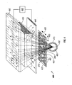
- FIG. 1 is a symbolic diagram of an apparatus 100 for inspecting an object 105 configured according to a first illustrative embodiment of the invention.
- a radiation source 110 positioned to illuminate an inspected region 115 of object 105 may take the form of a fixed position x-ray tube 120, capable of focusing the electron anode spot to a sufficiently small diameter to meet the image resolution requirement, positioned within stationary beam collimator 125.
- This arrangement of x-ray tube 120 and collimator 125 forms a fan beam 130 of radiation having narrow angular dispersion in one transverse axis (perpendicular to the plane of the figure) and a broad angular dispersion (typically 45 to 90 degrees) in the other transverse axis 135.
- Fan beam 130 defines a plane transverse to the direction of movement of object 105 during the image construction process, as discussed below.
- Fan beam 130 is spatially and temporally modulated by a modulator 140 positioned in the beam path.
- Modulator 140 may be implemented as a movable mask 145, constructed from a suitable material and to an appropriate thickness that is substantially opaque at the wavelength(s) emitted by radiation source 110, such that portions of fan beam 130 striking the intact areas of mask 145 are blocked from illuminating corresponding segments of object 105 (as used herein, the term "segment” denotes a discrete area forming a part of the inspected region of object 105).
- Mask 145 is adapted with a series of apertures or transmissive windows 150 that allow several discrete sectors 155 of the fan beam to emerge and illuminate corresponding segments of inspected region 115 of object 105 at any given position of mask 145.
- apertures 150 are arranged and sized to define (in connection with the adjacent opaque areas of mask 145) a one-dimensional encoding array 160.
- encoding array 160 has an open area of approximately 50%, so that about half of the total fan beam flux is available to illuminate object 105 at any position of mask 145.
- An optional transmission detector 165 which may be segmented or unsegmented, intersects the plane of fan beam on the opposite side of object 105.
- At least one unsegmented backscatter detector 170 is placed on the near side of object 105 to receive radiation backscattered from object 105.
- backscattered radiation is considered to include source radiation scattered by the inspected object 105 both incoherently (as Compton scatter) and coherently (as Rayleigh scatter), and so backscatter detector 170 may detect one or more of these types of backscattered radiation.
- Backscatter detector 170 and optional transmission detector 165 convey signals representative of the intensity of the received radiation to processor 180, which processes the signals to construct an image of the inspected region 115.
- Backscatter detector 170 is preferably configured with as large an active detection area as practical so that a large fraction of the backscattered radiation may be detected.
- Certain implementations of the invention may utilize an array comprising two or more unsegmented backscatter detectors; however, in contradistinction to prior art approaches utilizing segmented backscatter detectors, the spatial resolution of the image of the inspected object is not determined by the size and/or number of the backscatter detectors.
- Mask 145 may be configured as a cylinder (or other continuous surface, such as loop or chain) having a central axis around which the mask is shifted (indexed) in a sequence of discrete rotational positions.
- mask 145 may be rotated in a continuous (non-indexed) manner.
- mask 145 may be controllably rotated by any suitable transport mechanism (not depicted), such as a stepper or voice-coil motor in mechanical association with the mask.
- mask 145 may take a planar shape, in which case it is progressively shifted by a suitable transport mechanism parallel to axis 135 in a sequence of discrete translational positions.
- the pattern of apertures 150 in mask 145 follows a sequence selected to obtain satisfactory image resolution and signal-to-noise ratio.
- the prior art see, e.g., Gottesman et al., "New Family of Binary Arrays for Coded Aperture Imaging,” Applied Optics, 28(20): 4344-4352 (1989 ), the entirety of which is incorporated by reference) details techniques for generating one-dimensional and two-dimensional uniform redundant arrays (URA) and modified uniform redundant array (MURA) that have optimal properties for coded aperture imaging applications, including a high fraction of open area (approximately 50% of the total area) and a decoding function that is "unimodular", yielding a uniform noise response across the image field.
- UUA uniform redundant array
- MURA modified uniform redundant array
- FIG. 2 depicts an example of an encoding array 160 consisting of a set of apertures 150 arranged in a linear MURA pattern of length 37.
- Masks having URA and MURA patterns also have the property that cyclic shifts of the mask pattern preserve the uniform response.
- the aforementioned Gottesman et al. reference also explains how to generate the decoding function associated with each URA or MURA, and how to apply the decoding function to the encoded data to produce an image.
- Other methods that may be employed to generate suitable one-dimensional and/or two-dimensional encoding arrays include product array, m-sequence, pn-sequence, and Hadamard difference set, all of which are described in detail in the prior art.
- Mask 145 is positioned and sized such that encoding array 160 or a cyclic shift of the encoding array modulates fan beam 130 at any instant.
- the length of encoding array 160 must match or exceed the extent of the arc of fan beam 130 at modulator 140.
- the full rotation of a cylindrical mask (such as mask 145) or the full translational shift of a planar mask may include one or several repeats of the encoding array pattern, but not more than one array length of the mask may be allowed to encode the usable portion of fan beam 130 at any one position of mask 145.
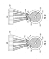
- encoding array 160 modulates fan beam 130 in a cyclical manner, such that the several segments of the inspected region of object 105 receive varying amounts of radiation according to the encoding sequence. It is noted that a segment in spatial correspondence to a blocked (intact) region of mask 145 may receive a small amount (relative to the amount received when it is in correspondence to an aperture 150) of spurious radiation transmitted through apertures 150 adjacent to the blocked region or reflected or scattered from other surfaces of apparatus 100. The effect of the movement of mask 145 is illustrated by FIGS. 3A and 3B. FIG.
- FIG. 3A depicts the illumination pattern projected on segments 305 of an inspected region of object 105 (which, in this case, constitutes a narrow band defined by the intersection of the full fan beam 130 with object 105) when mask 145 is at an initial rotational position.
- the illumination pattern is advanced in the direction of rotation.
- Each segment of the inspected region of object 105 receives the encoding sequence of illumination with a phase shift corresponding to the position of mask 145 relative to the segment.
- each segment receives varying amount of radiation in accordance with the encoding sequence
- radiation emanating from object 105 strikes backscatter detector 170 and optional transmission detector 165, which generate signals representative of the intensities of the received radiation.
- the detector responses are recorded for at least one full cycle of the mask movement, and then processor 180 applies the appropriate decoding function to each detector's temporal response to generate an image of the inspected region (i.e., a line scan).
- Object 105 is then advanced (e.g., by a conveyor) in the direction indicated by arrow 185 to a new position relative to the plane of fan beam 130 in order to acquire an image of an adjacent region (line scan) of object 105.
- the several steps of alternating illumination, detection, recording, decoding, and advancement of object 105 are repeatedly performed until the complete image of object 105 is constructed.
- This image may, for example, be displayed on a monitor for real-time viewing by an operator, or stored for later review and analysis.
- embodiments of the present invention do not depend on the use of spatially varying illumination sequences having unique characteristic frequencies in order to recover spatial information from the detector signal.
- the sequences in which different segments 305 receive illumination may (and typically will) share a number of the same frequencies.
- modulator 140 may be considered to provide nonharmonic modulation of beam 130.
- FIG. 4 depicts an inspection apparatus 400 constructed in accordance with a second embodiment, which employs a "flood" beam (i.e., an illuminating beam expanded in two orthogonal transverse dimensions) rather than the fan beam described in connection with the FIG. 1 embodiment, and thereby utilizes a substantially greater fraction of the source's available flux.
- radiation source 405 is provided having an x-ray tube 410 and a collimator 415 arranged around x-ray tube 410 to allow radiation to be emitted as a flood beam 420 with broad angular dispersion in two transverse dimensions.
- Flood beam 420 passes through a modulator 422, comprising a two-dimensional mask 425 which can be translated in two orthogonal axes 430 and 435 (using, for example, one or more stepper motors in mechanical association with mask 425) to obtain the full complement of beam patterns required to encode the image.
- mask 425 may be formed as a cylinder, and the illumination sequence is effected by both rotating and translating the mask.
- At least one unsegmented backscatter detector 440 is positioned to receive radiation scattered from object 450.
- An optional transmission detector 455, which may be segmented or unsegmented, is positioned to receive radiation transmitted through object 450.
- optional transmission detector 455 should be sufficiently large to intercept the full flood beam (noting, however, that a smaller detector may be employed if forward-scattered or forward-emitted radiation rather than transmitted radiation is to be detected).
- Backscatter detector 440 and optional transmission detector 455 convey signals representative of the intensity of the received radiation to processor 460, which processes the signals to construct a two-dimensional image of the inspected region.
- the full image of object 450 may be acquired while object 450 is held stationary; otherwise, the full image may be constructed by generating several partial images each acquired while object 450 is held at a different position relative to flood beam 420 so as to scan the (two-dimensional) inspected region over the full extent of object 450, and then stitching the partial images together to produce a full image.
- modulator 422 provides nonharmonic modulation of beam 420, since apparatus 400 does not rely on the use of spatially varying illumination sequences having unique characteristic frequencies in order to recover spatial information from the detector signal.
- Mask 425 is adapted with a pattern of apertures or transmissive windows 465 defining a two-dimensional encoding array 470.
- Encoding array 470 may be generated according to the square MURA scheme described by the aforementioned Gottesman et al. reference.
- An example of an encoding pattern produced by the square MURA scheme is shown in FIG. 5 .
- the movable mask must be large enough to cover the array area plus full overlaps in each of the two translation dimensions. Therefore, the mask has about four times the area of the array.
- FIG. 6 depicts a mask 425 designed in this manner based on the encoding pattern of FIG. 5 .
- FIG. 7 shows an encoding pattern of the scrolling type for a 6x6 pixel array that may be configured as a two dimensional mask in the form of a flat rectangle, a continuous band, or a flat disk.
- An encoding pattern of the scrolling type for an m by n pixel image array may be constructed from an encoding sequence of length l where l is greater than m*n and is relatively prime to the array width m.
- the encoding sequence of length l may be a linear URA or linear MURA as described in the aforementioned Gottesman et al. reference ( FIG.
- the encoding pattern is formed by applying the encoding sequence of length l repeatedly across the scroll width m, and wrapping around to the beginning of the next line as necessary, for a total of l lines. The full mask pattern then has the dimensions of m*l. If the mask does not wrap from the end to the start like a continuous band, then the first ( n - 1) rows must be repeated at the end of the pattern to accommodate overlap.
- FIG. 8 shows a design for a disk-shaped mask 805 using an encoding pattern of the scrolling type for a 6x6 pixel sector-shaped image array.
- Each aperture 810 is sized, shaped and arranged such that for certain discrete increments of the mask's rotation the hole coordinates align with a predetermined grid. In this particular design, all apertures 810 are identical in size and shape.
- a mask designed to translate or rotate in a single direction facilitates mask motion that is continuous rather than incremental.
- Continuous mask motion combined with continuous operation of the radiation source and detector will naturally lead to a degree of image blurring along the direction of motion.
- Operation of the radiation source in discrete pulses or bursts synchronized with the mask advancement can reduce or eliminate the blurring effect.
- the detector may be gated on and off in a manner synchronous with the mask advancement.
- the coded aperture imaging technique employed by embodiments of the present invention represents a significant improvement of signal-to-noise ratio (SNR) relative to alternative imaging techniques.
- Fenimore Coded Aperture Imaging: Predicted Performance of Uniformly Redundant Arrays", Applied Optics, 17(22): 3562-3570 (1978 ) presents a formula for calculating the improvement of SNR (the "multiplexing advantage") of a URA-based coded aperture system over a pinhole camera system of equivalent resolution.
- the same formula describes the multiplexing advantage of a MURA or URA-based coded beam system over a flying spot system of equivalent resolution and source intensity.
- the disclosed embodiments utilize a beam of x-rays to interrogate the inspected object
- alternative implementations may utilize radiation located elsewhere in the electromagnetic spectrum (e.g., gamma rays, UV radiation, visible light), particle beams (e.g., a neutron beam), or even an ultrasonic or acoustic beam.
- the beam may be spatially and temporally modulated by any suitable device or combination of devices in place of the moving mask arrangement disclosed above.
- the modulator may take the form of a one-dimensional or two-dimensional array of shuttered apertures, whereby each aperture has a shutter associated therewith that is programmed to open and close in accordance with a specified sequence.
- the mask may be replaced with a structure having a pattern constructed from elements of a radiation reflecting medium (for example, pyrolytic graphite) to obtain a coded beam.
- the encoding pattern for a reflecting medium is merely the complement of an encoding pattern for a mask.
- the modulator may take the form of a cylindrical drum-like structure rotatable about a central axis, the drum having a series of surfaces of reflecting and non-reflecting material extending generally parallel to the central axis.
- the modulator may take the form of an array of radiation emitters, the output of each emitter being independently modulated (in a manner similar to an LED projector) so that the resultant composite beam has a prescribed spatial distribution at any given time.
- the collimator structures for forming the radiation beam may be placed between the modulator (e.g., a movable mask) and the inspected object, rather than (as depicted in FIGS. 1 and 4 ) between the x-ray tube and the modulator.
- the modulator e.g., a movable mask
- a portable inspection apparatus may be constructed by integrating the source, modulator, detector and processor components into a single housing.
Landscapes
- Chemical & Material Sciences (AREA)
- Health & Medical Sciences (AREA)
- Life Sciences & Earth Sciences (AREA)
- General Physics & Mathematics (AREA)
- Physics & Mathematics (AREA)
- Pathology (AREA)
- Analytical Chemistry (AREA)
- Biochemistry (AREA)
- General Health & Medical Sciences (AREA)
- Immunology (AREA)
- Spectroscopy & Molecular Physics (AREA)
- Molecular Biology (AREA)
- High Energy & Nuclear Physics (AREA)
- Crystallography & Structural Chemistry (AREA)
- Analysing Materials By The Use Of Radiation (AREA)
- Measurement Of Radiation (AREA)
- Apparatus For Radiation Diagnosis (AREA)
- Investigating Or Analysing Materials By Optical Means (AREA)
Claims (24)
- Vorrichtung (100) zum Untersuchen eines Objekts (105, 450), umfassend:eine Strahlungsquelle (110, 405) zum Erzeugen eines Beleuchtungsstrahls, welcher entlang mindestens einer Querdimension aufgeweitet ist,einen Modulator (140, 422), welcher in dem Beleuchtungsstrahlengang zwischen der Strahlungsquelle (110, 405) und dem Objekt (105, 450) angeordnet ist, um den Beleuchtungsstrahl auf eine zeitlich variierende Art räumlich zu modulieren, so dass jedes Segment einer untersuchten Region (115) des Objekts (105, 450) variierende Mengen an Strahlung nach einer vorbestimmten zeitlichen Sequenz empfängt;mindestens einen Detektor (170; 440), welcher positioniert ist, um rückgestreute Strahlung zu empfangen, welche von dem Objekt (105) ausstrahlt, als Reaktion auf das Auftreffen des Beleuchtungsstrahls auf der untersuchten Region (115); undeinen Prozessor (180, 460), welcher an dem mindestens einen Detektor (170; 440) angeschlossen ist, um eine Sequenz von Signalen, welche von dem mindestens einen Detektor (170; 440) erzeugt werden, zu verarbeiten, um ein Bild der untersuchten Region (115) aufzubauen;dadurch gekennzeichnet, dass die genannte zeitlich variierende Art des Modulierens des Beleuchtungsstrahls nichtharmonisch ist.
- Vorrichtung (100) nach Anspruch 1, welche weiterhin einen zweiten Detektor (165, 455) umfasst, welcher positioniert ist, um Strahlung zu empfangen, welche durch das Objekt (105, 450) übertragen oder in der Vorwärtsrichtung durch dieses gestreut wird.
- Vorrichtung (100) nach Anspruch 1 oder 2, wobei der Modulator (140, 422) eine Maske (145, 425, 805) umfasst, welche eine Kodierungsanordnung (160, 470) von durchsichtigen (150, 465, 810) und undurchsichtigen Bereichen aufweist, und einen Transportmechanismus zum wiederholenden Wechseln oder kontinuierlichen Bewegen der Kodierungsanordnung (160, 470) bezüglich des Beleuchtungsstrahls.
- Vorrichtung (100) nach Anspruch 3, wobei die Kodierungsanordnung (160) eine eindimensionale Anordnung ist.
- Vorrichtung (100) nach Anspruch 4, wobei die Maske (145) als eine durchgehende Fläche gebildet ist, und der Transportmechanismus ausgebildet ist, um die Maske (145) bezüglich der Strahlungsquelle (110) zu drehen.
- Vorrichtung (100) nach Anspruch 3, wobei die Kodierungsanordnung (470) eine zweidimensionale Anordnung ist.
- Vorrichtung (100) nach Anspruch 6, wobei der Transportmechanismus ausgebildet ist, um eine der folgenden Handlungen durchzuführen: Übersetzen der Maske (145, 425, 805) in erste und zweite Achsen (430, 435), welche im Wesentlichen quer zur Ausbreitungsachse des Beleuchtungsstrahls sind, oder Übersetzen und Drehen der Maske (145, 425, 805).
- Vorrichtung (100) nach Anspruch 6, wobei die Kodierungsanordnung umfänglich bezüglich der Maske (805) angeordnet ist, und der Transportmechanismus ausgebildet ist, um die Maske (805) zu drehen.
- Vorrichtung (100) nach Anspruch 3, wobei die Kodierungsanordnung (160, 470) eine oder eine Reihe von gleichmäßig redundanten Anordnungen oder abgeänderten gleichmäßig redundanten Anordnungen umfasst.
- Vorrichtung (100) nach Anspruch 3, wobei die Summe der transparenten Bereiche (150, 465, 810) ungefähr 50 Prozent des gesamten Bereichs der Kodierungsanordnung (160, 470) beträgt.
- Vorrichtung (100) nach einem der Ansprüche 1 - 5, 9 und 10, wobei der Beleuchtungsstrahl ein Fächerstrahl (130) ist, welcher entlang einer ersten Dimension aufgeweitet ist.
- Vorrichtung (100) nach Anspruch 11, weiterhin umfassend eine Transportvorrichtung zum Bewegen des Objekts (105, 450) in einer im Allgemeinen zur ersten Dimension orthogonalen Richtung, so dass die untersuchte Region fortschreitend über das Objekt (105, 450) oder einen interessierenden Teil davon abgetastet wird.
- Vorrichtung (100) nach einem der Ansprüche 1 und 6 - 10, wobei der Beleuchtungsstrahl ein Flutlichtstrahl (420) ist, welcher entlang erster und zweiter Dimensionen (430, 435) aufgeweitet ist.
- Vorrichtung (100) nach einem der vorhergehenden Ansprüche, wobei der Beleuchtungsstrahl ein elektromagnetisches Strahlungsbündel ist.
- Vorrichtung (100) nach Anspruch 14, wobei der Beleuchtungsstrahl ein Röntgenstrahl ist.
- Vorrichtung (100) nach einem der Ansprüche 1 - 13, wobei der Beleuchtungsstrahl ein Teilchenstrahl ist.
- Vorrichtung (100) nach Anspruch 1, wobei der erste Detektor (170; 440) einen energiedispersiven Detektor umfasst, und der Prozessor (180, 460) ausgebildet ist, um ein Bild der Verteilung eines bestimmten Elements oder einer Gruppe von bestimmten Elementen im Objekt (105, 450) aufzubauen.
- Vorrichtung (100) nach Anspruch 1, wobei der mindestens eine Detektor (170, 440) ausgebildet ist, um vorzugsweise Strahlungsmerkmale einer ausgewählten Gruppe von bestimmten Elementen auszuwählen.
- Vorrichtung (100) nach Anspruch 1, wobei der Modulator (140, 422) eine bewegliche Oberfläche umfasst, auf welcher eine Kodierungsanordnung (160, 470) angeordnet ist, welche durch ein Muster von reflektierendem und nichtreflektierendem Material bestimmt ist.
- Verfahren zum Untersuchen eines Objekts (105, 450), umfassend folgende Schritte:Erzeugen eines Beleuchtungsstrahls, welcher entlang mindestens einer Querdimension aufgeweitet ist;Räumliches Modulieren auf zeitlich variierende Art des Beleuchtungsstrahls, so dass jedes Segment einer untersuchten Region (115) des Objekts (105, 450) variierende Mengen an Strahlung nach einer vorbestimmten zeitlichen Sequenz empfängt;Empfangen an einem ersten Detektor (170; 440) von rückgestreuter Strahlung, welche von dem Objekt (105, 450) ausstrahlt, als Reaktion auf ein Auftreffen des Beleuchtungsstrahls auf der untersuchten Region (115) und Erzeugen einer Sequenz von Signalen, welche repräsentativ für die Intensität der empfangenen Strahlung steht; undVerarbeiten der Sequenz von Signalen, um ein Bild der untersuchten Region (115) aufzubauen; dadurch gekennzeichnet, dass die zeitlich variierende Art des Modulierens des Beleuchtungsstrahls nichtharmonisch ist.
- Verfahren nach Anspruch 20, wobei der Schritt des räumlichen Modulierens des Strahls ein wiederholendes Wechseln oder kontinuierliches Bewegen bezüglich des Beleuchtungsstrahls einer Maske (145, 425, 805) umfasst, welche eine Kodierungsanordnung (160, 470) von durchsichtigen (150, 465, 810) und undurchsichtigen Bereichen aufweist.
- Verfahren nach einem der Ansprüche 20 und 21, weiterhin umfassend einen Schritt des wiederholenden Bewegens des Objekts (105, 450), so dass die untersuchte Region (115) fortschreitend über das Objekt (105, 450) oder einen interessierenden Teil davon abgetastet wird.
- Verfahren nach Anspruch 20, weiterhin umfassend das Empfangen an einem zweiten Detektor (165; 455) von Strahlung, welche durch das Objekt (105, 450) übertragen oder durch dieses gestreut wird.
- Verfahren nach Anspruch 20, wobei der Schritt des Verarbeitens der Sequenz von Signalen das Identifizieren von Strahlung, welche eine oder mehr Wellenlängen oder Energien hat, welche charakteristisch für ein bestimmtes Element oder eine Gruppe von bestimmten Elementen sind, und das Aufbauen eines Bilds der Verteilung des bestimmten Elements oder der Gruppe von bestimmten Elementen in dem Objekt enthält.
Applications Claiming Priority (2)
| Application Number | Priority Date | Filing Date | Title |
|---|---|---|---|
| US85387606P | 2006-10-24 | 2006-10-24 | |
| PCT/US2007/082428 WO2008127385A2 (en) | 2006-10-24 | 2007-10-24 | Apparatus for inspecting objects using coded beam |
Publications (2)
| Publication Number | Publication Date |
|---|---|
| EP2076793A2 EP2076793A2 (de) | 2009-07-08 |
| EP2076793B1 true EP2076793B1 (de) | 2016-01-06 |
Family
ID=39864530
Family Applications (1)
| Application Number | Title | Priority Date | Filing Date |
|---|---|---|---|
| EP07873569.3A Active EP2076793B1 (de) | 2006-10-24 | 2007-10-24 | Vorrichtung zum untersuchen von objekten unter verwendung eines kodierten strahls |
Country Status (7)
| Country | Link |
|---|---|
| US (1) | US7623614B2 (de) |
| EP (1) | EP2076793B1 (de) |
| JP (1) | JP2010507811A (de) |
| CN (1) | CN101568855A (de) |
| AU (1) | AU2007351440B2 (de) |
| CA (1) | CA2665872C (de) |
| WO (1) | WO2008127385A2 (de) |
Families Citing this family (55)
| Publication number | Priority date | Publication date | Assignee | Title |
|---|---|---|---|---|
| US20080253653A1 (en) * | 2007-04-12 | 2008-10-16 | Todd Gable | Systems and methods for improving visibility of scanned images |
| US7643611B2 (en) * | 2007-04-30 | 2010-01-05 | University Of Florida Research Foundation, Inc. | Method and apparatus for shadow aperture backscatter radiography (SABR) system and protocol |
| US8243353B1 (en) | 2008-04-07 | 2012-08-14 | Applied Science Innovations, Inc. | Holography-based device, system and method for coded aperture imaging |
| GB0823093D0 (en) * | 2008-12-19 | 2009-01-28 | Durham Scient Crystals Ltd | Apparatus and method for characterisation of materials |
| CN102365703A (zh) * | 2009-03-27 | 2012-02-29 | 皇家飞利浦电子股份有限公司 | 用于利用x射线管进行编码源成像的结构化的电子发射器 |
| US8304737B2 (en) * | 2009-10-02 | 2012-11-06 | Ut-Battelle, Llc | Apparatus and method to achieve high-resolution microscopy with non-diffracting or refracting radiation |
| US9157182B2 (en) * | 2010-05-14 | 2015-10-13 | Automated Vision, Llc | Systems, methods and computer program products for processing of coverings such as leather hides and fabrics for furniture and other products |
| US9421692B2 (en) | 2010-05-14 | 2016-08-23 | Automated Vision, Llc | Methods and computer program products for processing of coverings such as leather hides and fabrics for furniture and other products |
| US8457274B2 (en) | 2010-10-18 | 2013-06-04 | American Science And Engineering, Inc. | System and methods for intrapulse multi-energy and adaptive multi-energy X-ray cargo inspection |
| DE102010061182B4 (de) * | 2010-12-13 | 2013-02-07 | Presens Precision Sensing Gmbh | Sensoranordnung, Verfahren und Messsystem zur Erfassung der Verteilung wenigstens einer Veränderlichen eines Objekts |
| WO2013103408A1 (en) * | 2011-10-07 | 2013-07-11 | Duke University | Apparatus for coded aperture x-ray scatter imaging and method therefor |
| FR2981455B1 (fr) | 2011-10-14 | 2013-12-27 | Commissariat Energie Atomique | Dispositif d'imagerie x ou gamma portable et polyvalent pour l'examen non destructif de colis suspects, integrant les techniques d'imagerie en transmission et en retrodiffusion |
| WO2013078344A1 (en) * | 2011-11-22 | 2013-05-30 | Xinray Systems Inc | High speed, small footprint x-ray tomography inspection systems, devices, and methods |
| BR112014019517B1 (pt) * | 2012-02-14 | 2022-05-10 | American Science and Engineering, Inc | Detector de radiação de raio x |
| WO2013184213A2 (en) * | 2012-05-14 | 2013-12-12 | The General Hospital Corporation | A distributed, field emission-based x-ray source for phase contrast imaging |
| US8879688B2 (en) * | 2012-05-22 | 2014-11-04 | The Boeing Company | Reconfigurable detector system |
| JP6202484B2 (ja) * | 2012-08-10 | 2017-09-27 | 国立研究開発法人物質・材料研究機構 | 中性子撮像装置及びその使用方法 |
| US9833205B2 (en) * | 2012-08-27 | 2017-12-05 | Sony Corporation | X-ray output apparatus for reduction of superfluous radiation exposure |
| FR3000211B1 (fr) | 2012-12-20 | 2015-12-11 | Commissariat Energie Atomique | Dispositif d'eclairage par balayage , dispositif d'imagerie le comportant et procede de mise en oeurvre |
| WO2014121039A1 (en) * | 2013-01-31 | 2014-08-07 | Duke University | System for improved compressive tomography and method therefor |
| EP2976626A4 (de) * | 2013-03-22 | 2016-09-21 | Univ New York | Computerzugängliches medium zur modulierung einer röntgenstrahlintensität |
| WO2015023741A1 (en) | 2013-08-13 | 2015-02-19 | Duke University | Structured illumination for volumetric-molecular-imaging |
| US9934930B2 (en) * | 2014-04-18 | 2018-04-03 | Fei Company | High aspect ratio x-ray targets and uses of same |
| UA123038C2 (uk) | 2014-05-22 | 2021-02-10 | Аустреліан Нуклеар Саєнс Енд Текнолоджі Органісейшн | Візуалізація гамма-випромінювання |
| CN103983654B (zh) * | 2014-05-26 | 2016-09-14 | 中国科学院高能物理研究所 | 一种基于孔径编码技术的射线散射成像系统 |
| CN104267053A (zh) * | 2014-09-30 | 2015-01-07 | 包微微 | 一种新型液体违禁品检测仪 |
| CN106331442B (zh) | 2015-07-02 | 2021-01-15 | 松下知识产权经营株式会社 | 摄像装置 |
| CN105301669B (zh) * | 2015-12-04 | 2019-01-04 | 同方威视技术股份有限公司 | 安检设备和射线探测方法 |
| JP6738644B2 (ja) | 2016-04-15 | 2020-08-12 | 三星電子株式会社Samsung Electronics Co.,Ltd. | 撮像装置及び撮像方法 |
| US10754057B2 (en) * | 2016-07-14 | 2020-08-25 | Rapiscan Systems, Inc. | Systems and methods for improving penetration of radiographic scanners |
| US10753869B2 (en) * | 2016-07-29 | 2020-08-25 | William Marsh Rice University | Lensless imaging device for microscopy and fingerprint biometric |
| JP6395275B2 (ja) * | 2017-04-13 | 2018-09-26 | 国立研究開発法人物質・材料研究機構 | X線撮像装置及びその使用方法 |
| DE102017111215B4 (de) * | 2017-05-23 | 2024-02-08 | Infineon Technologies Ag | Vorrichtung und Verfahren zum Detektieren einer Eigenschaft aus elektromagnetischen Strahlungssensordaten |
| WO2019006310A1 (en) * | 2017-06-29 | 2019-01-03 | Cuadros Angela | PIXELIZED K-ENCODED OPENING SYSTEM FOR X-RAY IMAGING WITH COMPRESSION SPECTRUM |
| MX2020002223A (es) * | 2017-10-20 | 2020-12-09 | Australian Nuclear Science & Tech Org | Sistema y metodo de formacion compresiva de imagenes. |
| CN108227027B (zh) * | 2017-12-29 | 2020-12-01 | 同方威视技术股份有限公司 | 车载背散射检查系统 |
| CN108008458B (zh) * | 2017-12-29 | 2020-09-08 | 同方威视技术股份有限公司 | 车载背散射检查系统 |
| CN108490497B (zh) * | 2018-02-05 | 2024-03-22 | 清华大学 | 安检系统和方法 |
| CN108646260B (zh) * | 2018-07-02 | 2024-01-05 | 中国科学院西安光学精密机械研究所 | 一种凝视型无镜头激光三维成像装置及成像方法 |
| CN109273131B (zh) * | 2018-10-31 | 2024-07-02 | 同方威视技术股份有限公司 | 准直器组件和射线检测设备 |
| US10948614B2 (en) | 2018-11-01 | 2021-03-16 | H3D, Inc. | Imaging system with one or more mask units and corresponding method of recording radiation |
| US11399788B2 (en) * | 2019-01-15 | 2022-08-02 | Duke University | Systems and methods for tissue discrimination via multi-modality coded aperture x-ray imaging |
| US11501474B2 (en) | 2019-02-18 | 2022-11-15 | Argospect Technologies Inc. | Collimators for medical imaging systems and image reconstruction methods thereof |
| WO2021025898A1 (en) * | 2019-08-02 | 2021-02-11 | Videray Technologies, Inc. | Enclosed x-ray chopper wheel |
| EP4248196A4 (de) * | 2020-11-21 | 2024-10-30 | Bar-Ilan University | System und verfahren zur abbildung chemischer elemente in einer probe |
| US11701077B2 (en) * | 2021-02-25 | 2023-07-18 | Uchicago Argonne, Llc | Coded-mask-based X-ray phase-contrast and dark-field imaging |
| CN113466956B (zh) * | 2021-06-18 | 2022-04-08 | 南京航空航天大学 | 一种基于随机厚度液态掩模的加密辐射成像系统 |
| WO2023007496A1 (en) * | 2021-07-28 | 2023-02-02 | Bar Ilan University | Method and system for high photon energies imaging |
| CN113758952B (zh) * | 2021-08-20 | 2022-10-11 | 中国科学院上海光学精密机械研究所 | 基于动量编码的x射线衍射成像装置及方法 |
| CN115266730B (zh) * | 2022-07-27 | 2025-05-16 | 凌云光技术股份有限公司 | 一种基于快照压缩成像的缺陷检测方法及装置 |
| CN115753860B (zh) * | 2022-11-15 | 2025-04-11 | 南京航空航天大学 | 基于旋转调制准直器的元素分布成像装置及方法 |
| KR102810542B1 (ko) * | 2023-01-09 | 2025-05-26 | 제주대학교 산학협력단 | 부호화구경 기반 휴대용 이중입자 영상장비를 이용한 방사선량률 측정 방법 |
| CN116125517B (zh) * | 2023-02-13 | 2025-06-17 | 成都理工大学 | 基于旋转测量的单像素辐射成像方法及系统 |
| EP4704707A2 (de) | 2023-04-29 | 2026-03-11 | Videray Technologies, Inc. | Tragbares röntgensystem mit einer eigenständigen detektortafel |
| CN116660297A (zh) * | 2023-06-28 | 2023-08-29 | 北京亿特克科技有限公司 | 一种基于自校正的x射线编码成像方法及装置 |
Citations (1)
| Publication number | Priority date | Publication date | Assignee | Title |
|---|---|---|---|---|
| US4241404A (en) * | 1977-12-19 | 1980-12-23 | U.S. Philips Corporation | Device for computed tomography |
Family Cites Families (24)
| Publication number | Priority date | Publication date | Assignee | Title |
|---|---|---|---|---|
| US3749911A (en) * | 1970-06-30 | 1973-07-31 | Nasa | Collimator of multiple plates with axially aligned identical random arrays of apertures |
| US4209780A (en) | 1978-05-02 | 1980-06-24 | The United States Of America As Represented By The United States Department Of Energy | Coded aperture imaging with uniformly redundant arrays |
| US4360797A (en) | 1978-05-02 | 1982-11-23 | The United States Of America As Represented By The United States Department Of Energy | Coded aperture imaging with uniformly redundant arrays |
| US4392237A (en) | 1980-08-25 | 1983-07-05 | General Electric Company | Scanning x-ray inspection system |
| US4389633A (en) * | 1980-09-26 | 1983-06-21 | The United States Of America As Represented By The United States Department Of Energy | Coded aperture imaging with self-supporting uniformly redundant arrays |
| US4506374A (en) * | 1982-04-08 | 1985-03-19 | Technicare Corporation | Hybrid collimator |
| JPS61249452A (ja) * | 1985-04-30 | 1986-11-06 | 株式会社東芝 | X線診断装置 |
| US5098640A (en) * | 1990-01-10 | 1992-03-24 | Science Applications International Corporation | Apparatus and method for detecting contraband using fast neutron activation |
| US5606165A (en) * | 1993-11-19 | 1997-02-25 | Ail Systems Inc. | Square anti-symmetric uniformly redundant array coded aperture imaging system |
| US5666393A (en) | 1994-02-17 | 1997-09-09 | Annis; Martin | Method and apparatus for reducing afterglow noise in an X-ray inspection system |
| AU3295097A (en) | 1996-05-31 | 1998-01-05 | Massachusetts Institute Of Technology | Coded aperture imaging |
| WO1998020366A1 (en) * | 1996-11-08 | 1998-05-14 | American Science And Engineering, Inc. | Coded aperture x-ray imaging system |
| ATE272224T1 (de) * | 1997-11-17 | 2004-08-15 | Max Planck Gesellschaft | Konfokales spektroskopiesystem und -verfahren |
| US6453007B2 (en) | 1998-11-30 | 2002-09-17 | American Science And Engineering, Inc. | X-ray inspection using co-planar pencil and fan beams |
| EP1135700B1 (de) | 1998-11-30 | 2005-03-02 | American Science & Engineering, Inc. | Röntgenstrahluntersuchungssystem mit kegel- und bleistiftstrahlen aus einer gemeinsamen quelle |
| US6353227B1 (en) * | 1998-12-18 | 2002-03-05 | Izzie Boxen | Dynamic collimators |
| US6269142B1 (en) | 1999-08-11 | 2001-07-31 | Steven W. Smith | Interrupted-fan-beam imaging |
| EP1287388A2 (de) | 2000-06-07 | 2003-03-05 | American Science & Engineering, Inc. | Streu- und transmissionssystem von röntgenstrahlen ,mit kodierten strahlen |
| GB0019451D0 (en) * | 2000-08-09 | 2000-09-27 | Secr Defence | Imaging apparatus |
| WO2002056055A2 (en) | 2000-09-29 | 2002-07-18 | Massachusetts Inst Technology | Systems and methods for coded aperture imaging of radiation- emitting sources |
| JP4022385B2 (ja) * | 2001-10-29 | 2007-12-19 | 三井造船株式会社 | 放射線検出装置 |
| CA2427463A1 (en) | 2003-04-30 | 2004-10-30 | Her Majesty The Queen, In Right Of Canada, As Represented By The Minister Of National Defence | Detection of explosive devices using x-ray backscatter radiation |
| US6950495B2 (en) * | 2003-12-01 | 2005-09-27 | The Boeing Company | Backscatter imaging using Hadamard transform masking |
| CN1946342A (zh) * | 2004-04-21 | 2007-04-11 | 皇家飞利浦电子股份有限公司 | 锥束相干散射计算机断层摄影装置 |
-
2007
- 2007-10-24 US US11/923,532 patent/US7623614B2/en active Active
- 2007-10-24 CA CA2665872A patent/CA2665872C/en active Active
- 2007-10-24 WO PCT/US2007/082428 patent/WO2008127385A2/en not_active Ceased
- 2007-10-24 JP JP2009534843A patent/JP2010507811A/ja active Pending
- 2007-10-24 AU AU2007351440A patent/AU2007351440B2/en not_active Ceased
- 2007-10-24 EP EP07873569.3A patent/EP2076793B1/de active Active
- 2007-10-24 CN CNA2007800396990A patent/CN101568855A/zh active Pending
Patent Citations (1)
| Publication number | Priority date | Publication date | Assignee | Title |
|---|---|---|---|---|
| US4241404A (en) * | 1977-12-19 | 1980-12-23 | U.S. Philips Corporation | Device for computed tomography |
Also Published As
| Publication number | Publication date |
|---|---|
| EP2076793A2 (de) | 2009-07-08 |
| CN101568855A (zh) | 2009-10-28 |
| AU2007351440B2 (en) | 2012-12-06 |
| AU2007351440A1 (en) | 2008-10-23 |
| WO2008127385A2 (en) | 2008-10-23 |
| JP2010507811A (ja) | 2010-03-11 |
| US20080095298A1 (en) | 2008-04-24 |
| WO2008127385A3 (en) | 2009-07-16 |
| CA2665872C (en) | 2013-04-02 |
| CA2665872A1 (en) | 2008-10-23 |
| US7623614B2 (en) | 2009-11-24 |
Similar Documents
| Publication | Publication Date | Title |
|---|---|---|
| EP2076793B1 (de) | Vorrichtung zum untersuchen von objekten unter verwendung eines kodierten strahls | |
| US11754731B2 (en) | Gamma-ray imaging | |
| RU2444723C2 (ru) | Устройство и способ досмотра объектов | |
| US8304737B2 (en) | Apparatus and method to achieve high-resolution microscopy with non-diffracting or refracting radiation | |
| US20150346120A1 (en) | Scanning illuminating device, imaging device comprising same and method of implementation | |
| EP2329296A2 (de) | Vorrichtung zum bestimmen einer richtung zu einer strahlungsquelle | |
| US20130208859A1 (en) | Sample analysis | |
| US7136453B2 (en) | Apparatus for imaging objects on the remote side of a barrier using radiation | |
| AU2001276490A1 (en) | Apparatus for imaging objects on the remote side of a barrier using radiation | |
| JP2012110579A (ja) | 放射線管装置及び放射線画像撮影システム | |
| AU2001276493A1 (en) | Portable x-ray imaging apparatus | |
| Chirco et al. | Multipurpose detection system for advanced tomographic testings |
Legal Events
| Date | Code | Title | Description |
|---|---|---|---|
| PUAI | Public reference made under article 153(3) epc to a published international application that has entered the european phase |
Free format text: ORIGINAL CODE: 0009012 |
|
| 17P | Request for examination filed |
Effective date: 20090415 |
|
| AK | Designated contracting states |
Kind code of ref document: A2 Designated state(s): AT BE BG CH CY CZ DE DK EE ES FI FR GB GR HU IE IS IT LI LT LU LV MC MT NL PL PT RO SE SI SK TR |
|
| R17D | Deferred search report published (corrected) |
Effective date: 20090716 |
|
| RIC1 | Information provided on ipc code assigned before grant |
Ipc: G01T 1/29 20060101AFI20091119BHEP |
|
| DAX | Request for extension of the european patent (deleted) | ||
| RAP1 | Party data changed (applicant data changed or rights of an application transferred) |
Owner name: THERMO SCIENTIFIC PORTABLE ANALYTICAL INSTRUMENTS |
|
| 17Q | First examination report despatched |
Effective date: 20140703 |
|
| GRAP | Despatch of communication of intention to grant a patent |
Free format text: ORIGINAL CODE: EPIDOSNIGR1 |
|
| INTG | Intention to grant announced |
Effective date: 20150702 |
|
| GRAS | Grant fee paid |
Free format text: ORIGINAL CODE: EPIDOSNIGR3 |
|
| GRAA | (expected) grant |
Free format text: ORIGINAL CODE: 0009210 |
|
| AK | Designated contracting states |
Kind code of ref document: B1 Designated state(s): AT BE BG CH CY CZ DE DK EE ES FI FR GB GR HU IE IS IT LI LT LU LV MC MT NL PL PT RO SE SI SK TR |
|
| REG | Reference to a national code |
Ref country code: GB Ref legal event code: FG4D |
|
| REG | Reference to a national code |
Ref country code: CH Ref legal event code: EP |
|
| REG | Reference to a national code |
Ref country code: IE Ref legal event code: FG4D |
|
| REG | Reference to a national code |
Ref country code: AT Ref legal event code: REF Ref document number: 769307 Country of ref document: AT Kind code of ref document: T Effective date: 20160215 |
|
| REG | Reference to a national code |
Ref country code: DE Ref legal event code: R096 Ref document number: 602007044514 Country of ref document: DE |
|
| REG | Reference to a national code |
Ref country code: LT Ref legal event code: MG4D |
|
| REG | Reference to a national code |
Ref country code: NL Ref legal event code: MP Effective date: 20160106 |
|
| REG | Reference to a national code |
Ref country code: AT Ref legal event code: MK05 Ref document number: 769307 Country of ref document: AT Kind code of ref document: T Effective date: 20160106 |
|
| PG25 | Lapsed in a contracting state [announced via postgrant information from national office to epo] |
Ref country code: NL Free format text: LAPSE BECAUSE OF FAILURE TO SUBMIT A TRANSLATION OF THE DESCRIPTION OR TO PAY THE FEE WITHIN THE PRESCRIBED TIME-LIMIT Effective date: 20160106 |
|
| PG25 | Lapsed in a contracting state [announced via postgrant information from national office to epo] |
Ref country code: ES Free format text: LAPSE BECAUSE OF FAILURE TO SUBMIT A TRANSLATION OF THE DESCRIPTION OR TO PAY THE FEE WITHIN THE PRESCRIBED TIME-LIMIT Effective date: 20160106 Ref country code: FI Free format text: LAPSE BECAUSE OF FAILURE TO SUBMIT A TRANSLATION OF THE DESCRIPTION OR TO PAY THE FEE WITHIN THE PRESCRIBED TIME-LIMIT Effective date: 20160106 Ref country code: IT Free format text: LAPSE BECAUSE OF FAILURE TO SUBMIT A TRANSLATION OF THE DESCRIPTION OR TO PAY THE FEE WITHIN THE PRESCRIBED TIME-LIMIT Effective date: 20160106 Ref country code: GR Free format text: LAPSE BECAUSE OF FAILURE TO SUBMIT A TRANSLATION OF THE DESCRIPTION OR TO PAY THE FEE WITHIN THE PRESCRIBED TIME-LIMIT Effective date: 20160407 |
|
| PG25 | Lapsed in a contracting state [announced via postgrant information from national office to epo] |
Ref country code: SE Free format text: LAPSE BECAUSE OF FAILURE TO SUBMIT A TRANSLATION OF THE DESCRIPTION OR TO PAY THE FEE WITHIN THE PRESCRIBED TIME-LIMIT Effective date: 20160106 Ref country code: AT Free format text: LAPSE BECAUSE OF FAILURE TO SUBMIT A TRANSLATION OF THE DESCRIPTION OR TO PAY THE FEE WITHIN THE PRESCRIBED TIME-LIMIT Effective date: 20160106 Ref country code: IS Free format text: LAPSE BECAUSE OF FAILURE TO SUBMIT A TRANSLATION OF THE DESCRIPTION OR TO PAY THE FEE WITHIN THE PRESCRIBED TIME-LIMIT Effective date: 20160506 Ref country code: PL Free format text: LAPSE BECAUSE OF FAILURE TO SUBMIT A TRANSLATION OF THE DESCRIPTION OR TO PAY THE FEE WITHIN THE PRESCRIBED TIME-LIMIT Effective date: 20160106 Ref country code: PT Free format text: LAPSE BECAUSE OF FAILURE TO SUBMIT A TRANSLATION OF THE DESCRIPTION OR TO PAY THE FEE WITHIN THE PRESCRIBED TIME-LIMIT Effective date: 20160506 Ref country code: LV Free format text: LAPSE BECAUSE OF FAILURE TO SUBMIT A TRANSLATION OF THE DESCRIPTION OR TO PAY THE FEE WITHIN THE PRESCRIBED TIME-LIMIT Effective date: 20160106 Ref country code: LT Free format text: LAPSE BECAUSE OF FAILURE TO SUBMIT A TRANSLATION OF THE DESCRIPTION OR TO PAY THE FEE WITHIN THE PRESCRIBED TIME-LIMIT Effective date: 20160106 |
|
| REG | Reference to a national code |
Ref country code: FR Ref legal event code: PLFP Year of fee payment: 10 |
|
| REG | Reference to a national code |
Ref country code: DE Ref legal event code: R097 Ref document number: 602007044514 Country of ref document: DE |
|
| PG25 | Lapsed in a contracting state [announced via postgrant information from national office to epo] |
Ref country code: EE Free format text: LAPSE BECAUSE OF FAILURE TO SUBMIT A TRANSLATION OF THE DESCRIPTION OR TO PAY THE FEE WITHIN THE PRESCRIBED TIME-LIMIT Effective date: 20160106 Ref country code: DK Free format text: LAPSE BECAUSE OF FAILURE TO SUBMIT A TRANSLATION OF THE DESCRIPTION OR TO PAY THE FEE WITHIN THE PRESCRIBED TIME-LIMIT Effective date: 20160106 |
|
| PLBE | No opposition filed within time limit |
Free format text: ORIGINAL CODE: 0009261 |
|
| STAA | Information on the status of an ep patent application or granted ep patent |
Free format text: STATUS: NO OPPOSITION FILED WITHIN TIME LIMIT |
|
| PG25 | Lapsed in a contracting state [announced via postgrant information from national office to epo] |
Ref country code: SK Free format text: LAPSE BECAUSE OF FAILURE TO SUBMIT A TRANSLATION OF THE DESCRIPTION OR TO PAY THE FEE WITHIN THE PRESCRIBED TIME-LIMIT Effective date: 20160106 Ref country code: RO Free format text: LAPSE BECAUSE OF FAILURE TO SUBMIT A TRANSLATION OF THE DESCRIPTION OR TO PAY THE FEE WITHIN THE PRESCRIBED TIME-LIMIT Effective date: 20160106 Ref country code: CZ Free format text: LAPSE BECAUSE OF FAILURE TO SUBMIT A TRANSLATION OF THE DESCRIPTION OR TO PAY THE FEE WITHIN THE PRESCRIBED TIME-LIMIT Effective date: 20160106 |
|
| 26N | No opposition filed |
Effective date: 20161007 |
|
| PG25 | Lapsed in a contracting state [announced via postgrant information from national office to epo] |
Ref country code: BE Free format text: LAPSE BECAUSE OF FAILURE TO SUBMIT A TRANSLATION OF THE DESCRIPTION OR TO PAY THE FEE WITHIN THE PRESCRIBED TIME-LIMIT Effective date: 20160106 |
|
| PG25 | Lapsed in a contracting state [announced via postgrant information from national office to epo] |
Ref country code: BG Free format text: LAPSE BECAUSE OF FAILURE TO SUBMIT A TRANSLATION OF THE DESCRIPTION OR TO PAY THE FEE WITHIN THE PRESCRIBED TIME-LIMIT Effective date: 20160406 Ref country code: SI Free format text: LAPSE BECAUSE OF FAILURE TO SUBMIT A TRANSLATION OF THE DESCRIPTION OR TO PAY THE FEE WITHIN THE PRESCRIBED TIME-LIMIT Effective date: 20160106 |
|
| REG | Reference to a national code |
Ref country code: CH Ref legal event code: PL |
|
| REG | Reference to a national code |
Ref country code: IE Ref legal event code: MM4A |
|
| PG25 | Lapsed in a contracting state [announced via postgrant information from national office to epo] |
Ref country code: LI Free format text: LAPSE BECAUSE OF NON-PAYMENT OF DUE FEES Effective date: 20161031 Ref country code: CH Free format text: LAPSE BECAUSE OF NON-PAYMENT OF DUE FEES Effective date: 20161031 |
|
| PG25 | Lapsed in a contracting state [announced via postgrant information from national office to epo] |
Ref country code: LU Free format text: LAPSE BECAUSE OF NON-PAYMENT OF DUE FEES Effective date: 20161024 |
|
| REG | Reference to a national code |
Ref country code: FR Ref legal event code: PLFP Year of fee payment: 11 |
|
| PG25 | Lapsed in a contracting state [announced via postgrant information from national office to epo] |
Ref country code: IE Free format text: LAPSE BECAUSE OF NON-PAYMENT OF DUE FEES Effective date: 20161024 |
|
| PG25 | Lapsed in a contracting state [announced via postgrant information from national office to epo] |
Ref country code: HU Free format text: LAPSE BECAUSE OF FAILURE TO SUBMIT A TRANSLATION OF THE DESCRIPTION OR TO PAY THE FEE WITHIN THE PRESCRIBED TIME-LIMIT; INVALID AB INITIO Effective date: 20071024 Ref country code: CY Free format text: LAPSE BECAUSE OF FAILURE TO SUBMIT A TRANSLATION OF THE DESCRIPTION OR TO PAY THE FEE WITHIN THE PRESCRIBED TIME-LIMIT Effective date: 20160106 |
|
| PG25 | Lapsed in a contracting state [announced via postgrant information from national office to epo] |
Ref country code: TR Free format text: LAPSE BECAUSE OF FAILURE TO SUBMIT A TRANSLATION OF THE DESCRIPTION OR TO PAY THE FEE WITHIN THE PRESCRIBED TIME-LIMIT Effective date: 20160106 Ref country code: MC Free format text: LAPSE BECAUSE OF FAILURE TO SUBMIT A TRANSLATION OF THE DESCRIPTION OR TO PAY THE FEE WITHIN THE PRESCRIBED TIME-LIMIT Effective date: 20160106 Ref country code: MT Free format text: LAPSE BECAUSE OF NON-PAYMENT OF DUE FEES Effective date: 20161031 |
|
| REG | Reference to a national code |
Ref country code: FR Ref legal event code: PLFP Year of fee payment: 12 |
|
| PGFP | Annual fee paid to national office [announced via postgrant information from national office to epo] |
Ref country code: DE Payment date: 20240930 Year of fee payment: 18 |
|
| PGFP | Annual fee paid to national office [announced via postgrant information from national office to epo] |
Ref country code: GB Payment date: 20241010 Year of fee payment: 18 |
|
| PGFP | Annual fee paid to national office [announced via postgrant information from national office to epo] |
Ref country code: FR Payment date: 20241024 Year of fee payment: 18 |