EP2076895B1 - Procédé et système de guidage de la circulation pour réguler des flux de circulation dans lesquels figurent des véhicules de transport de produits dangereux ou spéciaux - Google Patents
Procédé et système de guidage de la circulation pour réguler des flux de circulation dans lesquels figurent des véhicules de transport de produits dangereux ou spéciaux Download PDFInfo
- Publication number
- EP2076895B1 EP2076895B1 EP07803276A EP07803276A EP2076895B1 EP 2076895 B1 EP2076895 B1 EP 2076895B1 EP 07803276 A EP07803276 A EP 07803276A EP 07803276 A EP07803276 A EP 07803276A EP 2076895 B1 EP2076895 B1 EP 2076895B1
- Authority
- EP
- European Patent Office
- Prior art keywords
- safety
- traffic
- critical
- hazardous material
- critical traffic
- Prior art date
- Legal status (The legal status is an assumption and is not a legal conclusion. Google has not performed a legal analysis and makes no representation as to the accuracy of the status listed.)
- Not-in-force
Links
Images

Classifications
-
- G—PHYSICS
- G08—SIGNALLING
- G08G—TRAFFIC CONTROL SYSTEMS
- G08G1/00—Traffic control systems for road vehicles
- G08G1/20—Monitoring the location of vehicles belonging to a group, e.g. fleet of vehicles, countable or determined number of vehicles
- G08G1/207—Monitoring the location of vehicles belonging to a group, e.g. fleet of vehicles, countable or determined number of vehicles with respect to certain areas, e.g. forbidden or allowed areas with possible alerting when inside or outside boundaries
Definitions
- the invention relates to a method for controlling traffic flows with dangerous goods or special transports through safety-critical traffic areas, such as tunnels, bridges or locks, according to the preamble of claim 1.
- the invention further relates to a traffic control system for controlling traffic flows with dangerous goods or special transports through safety-critical traffic areas, such as tunnels, bridges or locks, according to the preamble of claim 4.
- Traffic control systems which measure road conditions or traffic density, for example, and set traffic control signals, such as speed restrictions or general driving bans. Traffic control systems, which also take into account the traffic density, are based on non-contact detection devices for vehicles, such as optical cameras.
- WO 2006/088916 describes a method for monitoring traffic flows.
- systems of this kind are not suitable for controlling traffic flows with dangerous goods or special transports through safety-critical traffic areas, such as tunnels, bridges or locks, since information about the presence and type of, for example, hazardous goods would be necessary.
- the automated acquisition of this information can not be achieved with optical cameras alone.
- safety-critical traffic areas such as tunnels, bridges or locks
- Claim 1 relates to a method for controlling traffic flows with dangerous goods or special transports through safety-critical traffic areas, such as tunnels, bridges or locks.
- safety-relevant data are read out by means of a signal transmitter arranged on the dangerous goods or special transports when passing readers arranged in the safety-critical traffic area and transmitted to a central processing unit, the central processing unit being based on the safety-related data of all dangerous goods located in the safety-critical traffic area.
- or special transports determines a safety risk in the safety-critical traffic area, and sets traffic control signals that reduce the accident risk of dangerous goods or special transport in the safety-critical traffic area in order to avoid an undue risk of safety.
- the special transports may also be buses or heavy vehicles of all kinds.
- interference with the traffic flow thus takes place only when dangerous goods or special transports are actually located in the safety-critical traffic area.
- own signal generator are provided with which the dangerous goods or special transports are provided, such as RFID transponder.
- the safety risk can first be evaluated, which results, for example, in combination with another dangerous goods or special transport. If an impermissible safety risk is to be expected, according to the invention traffic control signals are set which reduce the accident risk of dangerous goods or special transport in the safety-critical traffic area.
- claim 2 provides that the central processing unit sets traffic control signals which prevent additional dangerous goods or special transport from entering the safety-critical traffic area, if there is already a dangerous goods or special transport in the safety-critical traffic area.
- the traffic control signal may consist of a stop signal for a dangerous goods or special transport located in the entry area of a safety-critical traffic area.
- Claim 4 relates to a traffic control system for controlling traffic flows with dangerous goods or special transports through safety-critical traffic areas, such as tunnels, bridges or locks.
- the dangerous goods or special transports are equipped with a signal generator for safety-relevant data
- the safety-critical traffic area readers are arranged for the signal generator, and a central processing unit is provided, on the one hand with the readers for transmission of when passing a Signal generator read, safety-related data is connected, and on the other hand with a traffic control device, in a safety-relevant data on the safety-critical all
- the safety risk determined by the traffic sector determines traffic control signals which reduce the accident risk of a dangerous goods or special transport in the safety-critical traffic area.
- the readers are arranged in the entry and exit area of the safety-critical traffic area, and the traffic control device comprises a controllable stop signal in the entry and exit area of the safety-critical traffic area.
- the signal transmitter is an RFID transponder.
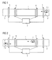
- the 1 to 4 show a possible embodiment of the method or traffic control system according to the invention, in which a safety-critical traffic area 1, such as a tunnel, should be accessible only for a dangerous goods or special transport 7.
- a safety-critical traffic area 1 such as a tunnel
- the 1 to 4 show only the dangerous goods or special transport 7, but the traffic flow is in addition to the dangerous goods or special transport 7 also from a variety of other vehicles, but do not represent an increased risk potential in safety-critical traffic area 1, and in the 1 to 4 are not shown.
- the safety-critical area 1 may be an exposed road section, a road tunnel, a railway tunnel, a lock in shipping, a bridge, etc.
- the hazardous goods or special transport 7.1 moves in the direction of the arrow on the safety-critical area 1, and is equipped with a signal generator 4, such as an RFID ("Radio Frequency Identification”) - transponder.
- the signal generator 4 contains safety-relevant data about the relevant vehicle, such as type of cargo, total amount of cargo, dimensions of the vehicle or vehicle weight.
- Dangerous goods or special transport 7.1 may also be any type of heavy vehicle, or other vehicles with increased protection requirements, such as buses.
- the safety-relevant data on the signal generator 4 are read by readers 5, which in the illustrated embodiment of FIG. 1 are arranged in the entry and exit area 2 of the safety-critical area 1.
- RFID transponders Different types of RFID transponders are known, which in principle can be used for methods according to the invention or traffic control systems. However, so-called “passive" RFID transponders are particularly advantageous do not need their own power supply, and therefore can be built small, light and cheap, and also have a long life.
- the readers 5 scan in a conventional manner the data contained on the RFID transponder.
- RFID transponders which have their own energy supply, for example to increase the range of the data exchange.
- RFID transponders of this type are also known as "semi-active" or “active” transponders.
- the reading devices 5 can also be designed as receiving devices for the data transmitted by the RFID transponder.
- the reader 5 transmits the data using a cable connection, or a wireless connection based on UMTS or GPRS to the central processing unit 3.
- the central processing unit 3 can be located in spatial proximity to the safety-critical traffic area 1, such as in the monitoring center of a tunnel, or also spatially far away, for example in a central traffic control center, which monitors several road sections. Based on the safety-related data of all dangerous goods or special transports 7.n, the central processing unit 3 determines a safety risk in the safety-critical traffic area 1 and sets traffic control signals that avoid the accident risk of dangerous goods or special transports 7.n in the safety-critical area in order to avoid an inadmissible safety risk Reduce traffic area 1.
- the traffic control device 6 such as a controllable stop signal, is therefore controlled by the central processing unit 3 so that it allows an entry of dangerous goods or special transport 7.1.
- the sum of the charged, combustible substances of two dangerous goods transports 7.1 and 7.2 could overtax the safety systems of a tunnel, or one can not enter buses into the tunnel during the passage of a dangerous goods transport 7.1 for safety reasons, etc.
- about permissible load for a bridge would be exceeded if additional dangerous goods or special transports 7.n are permitted in the safety-critical area 1, in this case a bridge.
- the passage of dangerous goods or special transport 7.2 should be temporarily prohibited, so that the central processing unit 3 sends to the corresponding traffic control device 6, for example, a stop signal ( FIG. 3 ).
- a traffic control signal also temporarily a general speed limit or otherwise a measure known to the skilled person for traffic telematics for reducing the accident risk of dangerous goods or special transport 7.n in the safety-critical traffic area 1.
- the first dangerous goods or special transport 7.1 When leaving the safety-critical traffic area 1, the first dangerous goods or special transport 7.1 passes a reading device 5, which reads out the safety-related data of the dangerous goods or special transport 7.1 in question and transmits it to the central processing unit 3. The central processing unit 3 is thus informed that the dangerous goods or special transport 7.1 has left the safety-critical traffic area 1. Since there is no further dangerous goods or special transport 7.n in the safety-critical traffic area 1, the passage for the dangerous goods or special transport 7.2 is released ( FIG. 4 ).
- signal generators 4 such as RFID transponders
- signal generators 4 in the context of the method according to the invention also has the advantage of being aware of the loading of dangerous goods or special transports 7.n at any time.
- rescue measures can be optimized, for example in the event of an accident.
- data about the dimensions of the respective dangerous goods or special transport 7.n can be compared with the local conditions of the safety-critical area 1, for example an underpass, in order to be able to identify potential hazards in this way.
- a method or a traffic control system for controlling traffic flows with dangerous goods or special transports 7.n is thus implemented by safety-critical traffic areas 1, which selectively minimizes security risks associated with dangerous goods or special transports 7.n without thereby affecting the general traffic flow for all unnecessarily hinder other vehicles.
Landscapes
- Physics & Mathematics (AREA)
- General Physics & Mathematics (AREA)
- Traffic Control Systems (AREA)
- Control Of Conveyors (AREA)
- Control Of Position, Course, Altitude, Or Attitude Of Moving Bodies (AREA)
- Train Traffic Observation, Control, And Security (AREA)
Claims (6)
- Procédé de commande de flux de circulation, ayant des transports ( 7.n ) de produits dangereux ou particuliers, dans des zones ( 1 ) de circulation critiques du point de vue de la sécurité, comme par exemple des tunnels, des ponts ou des sas, caractérisé en ce qu'on lit, à l'aide d'un générateur de signaux monté sur les transports ( 7.n ) de produits dangereux ou particuliers, des données pertinentes du point de vue de la sécurité lors du passage devant des appareils ( 5 ) de lecture disposés dans la zone ( 1 ) de circulation critique du point de vue de la sécurité et on les transmet à une unité ( 3 ) informatique centrale, l'unité (3) informatique centrale déterminant, à l'aide des données pertinentes du point de vue de la sécurité de tous les transports (7.n) de produits dangereux ou particuliers se trouvant dans la zone ( 1 ) de circulation critique du point de vue de la sécurité, un danger pour la sécurité dans la zone ( 1 ) de circulation critique du point de vue de la sécurité et, pour éviter un danger inadmissible pour la sécurité, met des signaux de conduite de la circulation, qui réduisent le danger d'accident d'un transport ( 7.n ) de produits dangereux ou particuliers dans la zone ( 1 ) de circulation critique du point de vue de la sécurité.
- Procédé suivant la revendication 1,
caractérisé en ce que l'unité ( 3 ) informatique centrale met des signaux de conduite de la circulation, qui empêchent un transport (7.2) de produits dangereux ou particuliers supplémentaire d'entrer dans la zone (1) de circulation critique du point de vue de la sécurité, si un transport ( 7.1 ) de produits dangereux ou particuliers se trouve déjà dans la zone ( 1 ) de circulation critique du point de vue de la sécurité. - Procédé suivant la revendication 1 ou 2,
caractérisé en ce que le signal de conduite de la circulation est constitué d'un signal d'arrêt pour un transport ( 7.2 ) de produits dangereux ou particuliers se trouvant dans la zone ( 2 ) d'entrée d'une zone (1) de circulation critique du point de vue de la sécurité. - Système de conduite de la circulation pour commander des flux de circulation ayant des transports ( 7.n ) de produits dangereux ou particuliers dans des zones ( 1 ) de circulation critiques du point de vue de la sécurité, comme par exemple des tunnels, des ponts ou des sas, caractérisé en ce que les transports ( 7.n ) de produits dangereux ou particuliers sont équipés d'un générateur de signaux, pour des données pertinentes du point de vue de la sécurité, et dans la zone ( 1 ) de circulation critique du point de vue de la sécurité sont disposés des appareils ( 5 ) de lecture pour les générateurs ( 4 ) de signaux et il est prévu une unité ( 3 ) informatique, qui est reliée, d'une part, aux appareils ( 5 ) de lecture pour une transmission des données pertinentes du point de vue de la sécurité lues lors du passage d'un générateur ( 4 ) de signaux et, d'autre part, à un dispositif ( 6 ) de conduite de la circulation, qui, pour un danger de sécurité déterminé au moyen des données pertinentes pour la sécurité de tous les transports ( 7.n ) de produits dangereux ou particuliers se trouvant dans la zone ( 1 ) de circulation critique du point de vue de la sécurité, met, pour empêcher un danger inadmissible pour la sécurité, des signaux de conduite de circulation, qui réduisent le danger d'accident d'un transport ( 7.n ) de produits dangereux ou particuliers dans la zone ( 1 ) de circulation critique du point de vue de la sécurité.
- Système de conduite suivant la revendication 4,
caractérisé en ce que les appareils (5) de lecture sont disposés dans une zone ( 2 ) d'entrée et de sortie de la zone de circulation critique du point de vue de la sécurité et le dispositif ( 6 ) de conduite de la circulation comprend un signal d'arrêt pouvant être commandé dans la zone ( 2 ) d'entrée et de sortie de la zone ( 1 ) de circulation critique du point de vue de la sécurité. - Système de conduite suivant la revendication 4 ou 5,
caractérisé en ce que le générateur ( 4 ) de signaux est un transpondeur RFID.
Applications Claiming Priority (2)
| Application Number | Priority Date | Filing Date | Title |
|---|---|---|---|
| DE102006048627A DE102006048627B3 (de) | 2006-10-13 | 2006-10-13 | Verfahren zur Steuerung von Verkehrsströmen mit Gefahrengut- oder Sondertransporten |
| PCT/EP2007/059317 WO2008043613A1 (fr) | 2006-10-13 | 2007-09-06 | Procédé et système de guidage de la circulation pour réguler des flux de circulation dans lesquels figurent des véhicules de transport de produits dangereux ou spéciaux |
Publications (2)
| Publication Number | Publication Date |
|---|---|
| EP2076895A1 EP2076895A1 (fr) | 2009-07-08 |
| EP2076895B1 true EP2076895B1 (fr) | 2011-10-26 |
Family
ID=38626961
Family Applications (1)
| Application Number | Title | Priority Date | Filing Date |
|---|---|---|---|
| EP07803276A Not-in-force EP2076895B1 (fr) | 2006-10-13 | 2007-09-06 | Procédé et système de guidage de la circulation pour réguler des flux de circulation dans lesquels figurent des véhicules de transport de produits dangereux ou spéciaux |
Country Status (5)
| Country | Link |
|---|---|
| US (1) | US8188888B2 (fr) |
| EP (1) | EP2076895B1 (fr) |
| AT (1) | ATE531025T1 (fr) |
| DE (1) | DE102006048627B3 (fr) |
| WO (1) | WO2008043613A1 (fr) |
Families Citing this family (5)
| Publication number | Priority date | Publication date | Assignee | Title |
|---|---|---|---|---|
| ITMI20121926A1 (it) * | 2012-11-13 | 2014-05-14 | Project Automation S P A | Apparato e metodo di controllo del transito di merci perisolose in galleria |
| DE102013108034B3 (de) * | 2013-07-26 | 2015-01-08 | Deutsches Zentrum für Luft- und Raumfahrt e.V. | Verfahren zur automatischen Kontrolle des Einfahrens eines Straßenfahrzeuges in einen kontrollierten Straßenabschnitt, fahrzeugseitiges System dafür sowie Computerprogramm |
| DE102019214445B4 (de) * | 2019-09-23 | 2026-01-08 | Robert Bosch Gmbh | Verfahren zum Assistieren eines Kraftfahrzeugs |
| DE102019214453B4 (de) * | 2019-09-23 | 2026-01-15 | Robert Bosch Gmbh | Verfahren zum Ausführen einer Funktion eines Kraftfahrzeugs |
| EP4256546A2 (fr) * | 2020-12-04 | 2023-10-11 | MOVYON S.p.A. | Système de contrôle de l'accès de véhicules à une section de route soumise à une limitation de charge |
Family Cites Families (10)
| Publication number | Priority date | Publication date | Assignee | Title |
|---|---|---|---|---|
| US5008661A (en) * | 1985-09-27 | 1991-04-16 | Raj Phani K | Electronic remote chemical identification system |
| US5347274A (en) * | 1990-05-17 | 1994-09-13 | At/Comm Incorporated | Hazardous waste transport management system |
| DE19900721A1 (de) * | 1999-01-12 | 2000-07-13 | Johannes Krezdorn | Verkehrswarnsystem / Leitsystem |
| SE521694C2 (sv) | 1999-09-21 | 2003-11-25 | Kongelf Holding Ab | System för styrning av fordonsrörelser |
| JP2002265004A (ja) * | 2001-03-08 | 2002-09-18 | Nisscom Corp | 産業廃棄物の最終処分場搬入管理システム |
| US8502699B2 (en) * | 2001-09-28 | 2013-08-06 | Mct Technology, Llc | Integrated detection and monitoring system |
| AT500235B1 (de) | 2002-06-21 | 2007-05-15 | Joanneum Res Forschungsgesells | System und verfahren zur automatischen überwachung eines verkehrsweges |
| US7336178B2 (en) * | 2004-10-07 | 2008-02-26 | Le Michael Q | Method and apparatus for remote control vehicle identification |
| WO2006088916A2 (fr) | 2005-02-14 | 2006-08-24 | Regents Of The University Of Minnesota | Systeme de detection de position de vehicules utilisant des etiquettes routieres passives |
| US6995673B1 (en) * | 2005-04-04 | 2006-02-07 | Peter J. Osredkar | Transporting hazardous material using an optical reader or RFID reader |
-
2006
- 2006-10-13 DE DE102006048627A patent/DE102006048627B3/de not_active Expired - Fee Related
-
2007
- 2007-09-06 AT AT07803276T patent/ATE531025T1/de active
- 2007-09-06 WO PCT/EP2007/059317 patent/WO2008043613A1/fr not_active Ceased
- 2007-09-06 US US12/311,712 patent/US8188888B2/en not_active Expired - Fee Related
- 2007-09-06 EP EP07803276A patent/EP2076895B1/fr not_active Not-in-force
Also Published As
| Publication number | Publication date |
|---|---|
| EP2076895A1 (fr) | 2009-07-08 |
| WO2008043613A1 (fr) | 2008-04-17 |
| US20090322564A1 (en) | 2009-12-31 |
| DE102006048627B3 (de) | 2008-06-19 |
| US8188888B2 (en) | 2012-05-29 |
| ATE531025T1 (de) | 2011-11-15 |
Similar Documents
| Publication | Publication Date | Title |
|---|---|---|
| EP3373093B1 (fr) | Système de transport sans conducteur | |
| EP2250065B1 (fr) | Procédé de sécurisation de véhicules sur rails par des techniques de signalisation et système de sécurisation de ces véhicules | |
| EP1779354A2 (fr) | Systeme de guidage et de securite destine aux systemes de circulation complexes | |
| EP2076895B1 (fr) | Procédé et système de guidage de la circulation pour réguler des flux de circulation dans lesquels figurent des véhicules de transport de produits dangereux ou spéciaux | |
| EP3652099A1 (fr) | Procédé de configuration de paramètres de configuration concernant la sécurité dans un système de transport de personnes | |
| EP2870047B1 (fr) | Fonctionnement d'un véhicule ferroviaire | |
| EP3224777A1 (fr) | Procédé de surveillance d'un emplacement de stationnement | |
| DE102005030829A1 (de) | Verfahren zum Betrieb eines Lichtgitters und Lichtgitter | |
| EP3335961B1 (fr) | Procédé de validation du réglage d'une voie de train voisine pour un véhicule sur rails | |
| EP3373458B1 (fr) | Système de communication et ensemble de machines | |
| WO2019007870A1 (fr) | Téléphérique et procédé pour faire fonctionner un téléphérique | |
| DE202018101285U1 (de) | Überwachungseinrichtung zur Überwachung eines Durchgangs | |
| EP4124540A1 (fr) | Procédé et dispositif permettant de faire fonctionner un arrêt automatique pour un véhicule guidé sur rails | |
| EP3312073A1 (fr) | Procédé de contrôle d'un système ferroviaire et système ferroviaire | |
| DE102007041718B4 (de) | Anordnung und Verfahren zur Absicherung von Arbeitsstellen im Gleisbereich | |
| WO2016139031A1 (fr) | Procédé et dispositif de mise en œuvre d'une interdiction de croisement pour certains types de trains sur une portion de voie d'une installation ferroviaire | |
| DE4244393C1 (de) | Verkehrsmeßwerk- und Überwachungssystem | |
| DE102006044645A1 (de) | Verfahren und System zur Bestimmung der Position und Ausrichtung eines unbemannten Fahrzeugs sowie entsprechendes Fahrzeug | |
| EP3249476A1 (fr) | Capteur | |
| DE102020001677A1 (de) | Verfahren zur Absicherung einer Kommunikation zwischen einer fahrzeugexternen Service- und Überwachungseinheit und einem autonom fahrenden Fahrzeug, vorzugsweise einem Güter transportierenden Nutzfahrzeug | |
| DE19954408A1 (de) | Verfahren und Vorrichtung zum Kontrollieren des Betretens oder Verlassens eines Bereichs durch Personen oder bewegliche Sachen | |
| DE102023201555A1 (de) | Tracking von Kindern mittels CiCo- oder BiBo-System | |
| EP3807796B1 (fr) | Procédé de fonctionnement d'un système informatique | |
| DE19925523C2 (de) | Verfahren und Vorrichtung zum Kontrollieren des Betretens oder Verlassens eines Bereichs durch Personen oder bewegliche Sachen | |
| DE29818025U1 (de) | Vorrichtung zum Personen- und Kollisionsschutz an Krananlagen |
Legal Events
| Date | Code | Title | Description |
|---|---|---|---|
| PUAI | Public reference made under article 153(3) epc to a published international application that has entered the european phase |
Free format text: ORIGINAL CODE: 0009012 |
|
| 17P | Request for examination filed |
Effective date: 20090326 |
|
| AK | Designated contracting states |
Kind code of ref document: A1 Designated state(s): AT BE BG CH CY CZ DE DK EE ES FI FR GB GR HU IE IS IT LI LT LU LV MC MT NL PL PT RO SE SI SK TR |
|
| GRAP | Despatch of communication of intention to grant a patent |
Free format text: ORIGINAL CODE: EPIDOSNIGR1 |
|
| DAX | Request for extension of the european patent (deleted) | ||
| GRAS | Grant fee paid |
Free format text: ORIGINAL CODE: EPIDOSNIGR3 |
|
| GRAA | (expected) grant |
Free format text: ORIGINAL CODE: 0009210 |
|
| AK | Designated contracting states |
Kind code of ref document: B1 Designated state(s): AT BE BG CH CY CZ DE DK EE ES FI FR GB GR HU IE IS IT LI LT LU LV MC MT NL PL PT RO SE SI SK TR |
|
| REG | Reference to a national code |
Ref country code: GB Ref legal event code: FG4D Free format text: NOT ENGLISH |
|
| REG | Reference to a national code |
Ref country code: CH Ref legal event code: EP |
|
| REG | Reference to a national code |
Ref country code: IE Ref legal event code: FG4D |
|
| REG | Reference to a national code |
Ref country code: CH Ref legal event code: NV Representative=s name: SIEMENS SCHWEIZ AG |
|
| REG | Reference to a national code |
Ref country code: DE Ref legal event code: R096 Ref document number: 502007008546 Country of ref document: DE Effective date: 20111222 |
|
| REG | Reference to a national code |
Ref country code: NL Ref legal event code: T3 |
|
| LTIE | Lt: invalidation of european patent or patent extension |
Effective date: 20111026 |
|
| PG25 | Lapsed in a contracting state [announced via postgrant information from national office to epo] |
Ref country code: IS Free format text: LAPSE BECAUSE OF FAILURE TO SUBMIT A TRANSLATION OF THE DESCRIPTION OR TO PAY THE FEE WITHIN THE PRESCRIBED TIME-LIMIT Effective date: 20120226 Ref country code: LT Free format text: LAPSE BECAUSE OF FAILURE TO SUBMIT A TRANSLATION OF THE DESCRIPTION OR TO PAY THE FEE WITHIN THE PRESCRIBED TIME-LIMIT Effective date: 20111026 |
|
| PG25 | Lapsed in a contracting state [announced via postgrant information from national office to epo] |
Ref country code: LV Free format text: LAPSE BECAUSE OF FAILURE TO SUBMIT A TRANSLATION OF THE DESCRIPTION OR TO PAY THE FEE WITHIN THE PRESCRIBED TIME-LIMIT Effective date: 20111026 Ref country code: SI Free format text: LAPSE BECAUSE OF FAILURE TO SUBMIT A TRANSLATION OF THE DESCRIPTION OR TO PAY THE FEE WITHIN THE PRESCRIBED TIME-LIMIT Effective date: 20111026 Ref country code: GR Free format text: LAPSE BECAUSE OF FAILURE TO SUBMIT A TRANSLATION OF THE DESCRIPTION OR TO PAY THE FEE WITHIN THE PRESCRIBED TIME-LIMIT Effective date: 20120127 Ref country code: SE Free format text: LAPSE BECAUSE OF FAILURE TO SUBMIT A TRANSLATION OF THE DESCRIPTION OR TO PAY THE FEE WITHIN THE PRESCRIBED TIME-LIMIT Effective date: 20111026 Ref country code: PL Free format text: LAPSE BECAUSE OF FAILURE TO SUBMIT A TRANSLATION OF THE DESCRIPTION OR TO PAY THE FEE WITHIN THE PRESCRIBED TIME-LIMIT Effective date: 20111026 Ref country code: PT Free format text: LAPSE BECAUSE OF FAILURE TO SUBMIT A TRANSLATION OF THE DESCRIPTION OR TO PAY THE FEE WITHIN THE PRESCRIBED TIME-LIMIT Effective date: 20120227 |
|
| REG | Reference to a national code |
Ref country code: IE Ref legal event code: FD4D |
|
| PG25 | Lapsed in a contracting state [announced via postgrant information from national office to epo] |
Ref country code: CY Free format text: LAPSE BECAUSE OF FAILURE TO SUBMIT A TRANSLATION OF THE DESCRIPTION OR TO PAY THE FEE WITHIN THE PRESCRIBED TIME-LIMIT Effective date: 20111026 |
|
| PG25 | Lapsed in a contracting state [announced via postgrant information from national office to epo] |
Ref country code: IE Free format text: LAPSE BECAUSE OF FAILURE TO SUBMIT A TRANSLATION OF THE DESCRIPTION OR TO PAY THE FEE WITHIN THE PRESCRIBED TIME-LIMIT Effective date: 20111026 Ref country code: CZ Free format text: LAPSE BECAUSE OF FAILURE TO SUBMIT A TRANSLATION OF THE DESCRIPTION OR TO PAY THE FEE WITHIN THE PRESCRIBED TIME-LIMIT Effective date: 20111026 Ref country code: EE Free format text: LAPSE BECAUSE OF FAILURE TO SUBMIT A TRANSLATION OF THE DESCRIPTION OR TO PAY THE FEE WITHIN THE PRESCRIBED TIME-LIMIT Effective date: 20111026 Ref country code: BG Free format text: LAPSE BECAUSE OF FAILURE TO SUBMIT A TRANSLATION OF THE DESCRIPTION OR TO PAY THE FEE WITHIN THE PRESCRIBED TIME-LIMIT Effective date: 20120126 Ref country code: DK Free format text: LAPSE BECAUSE OF FAILURE TO SUBMIT A TRANSLATION OF THE DESCRIPTION OR TO PAY THE FEE WITHIN THE PRESCRIBED TIME-LIMIT Effective date: 20111026 Ref country code: SK Free format text: LAPSE BECAUSE OF FAILURE TO SUBMIT A TRANSLATION OF THE DESCRIPTION OR TO PAY THE FEE WITHIN THE PRESCRIBED TIME-LIMIT Effective date: 20111026 |
|
| PG25 | Lapsed in a contracting state [announced via postgrant information from national office to epo] |
Ref country code: RO Free format text: LAPSE BECAUSE OF FAILURE TO SUBMIT A TRANSLATION OF THE DESCRIPTION OR TO PAY THE FEE WITHIN THE PRESCRIBED TIME-LIMIT Effective date: 20111026 |
|
| PLBE | No opposition filed within time limit |
Free format text: ORIGINAL CODE: 0009261 |
|
| STAA | Information on the status of an ep patent application or granted ep patent |
Free format text: STATUS: NO OPPOSITION FILED WITHIN TIME LIMIT |
|
| 26N | No opposition filed |
Effective date: 20120727 |
|
| PGFP | Annual fee paid to national office [announced via postgrant information from national office to epo] |
Ref country code: FI Payment date: 20120912 Year of fee payment: 6 Ref country code: GB Payment date: 20120917 Year of fee payment: 6 |
|
| REG | Reference to a national code |
Ref country code: DE Ref legal event code: R097 Ref document number: 502007008546 Country of ref document: DE Effective date: 20120727 |
|
| PGFP | Annual fee paid to national office [announced via postgrant information from national office to epo] |
Ref country code: TR Payment date: 20120829 Year of fee payment: 6 |
|
| PGFP | Annual fee paid to national office [announced via postgrant information from national office to epo] |
Ref country code: IT Payment date: 20120926 Year of fee payment: 6 |
|
| BERE | Be: lapsed |
Owner name: SIEMENS A.G. Effective date: 20120930 |
|
| PG25 | Lapsed in a contracting state [announced via postgrant information from national office to epo] |
Ref country code: ES Free format text: LAPSE BECAUSE OF FAILURE TO SUBMIT A TRANSLATION OF THE DESCRIPTION OR TO PAY THE FEE WITHIN THE PRESCRIBED TIME-LIMIT Effective date: 20120206 Ref country code: MC Free format text: LAPSE BECAUSE OF NON-PAYMENT OF DUE FEES Effective date: 20120930 |
|
| REG | Reference to a national code |
Ref country code: FR Ref legal event code: ST Effective date: 20130531 |
|
| PG25 | Lapsed in a contracting state [announced via postgrant information from national office to epo] |
Ref country code: BE Free format text: LAPSE BECAUSE OF NON-PAYMENT OF DUE FEES Effective date: 20120930 |
|
| PG25 | Lapsed in a contracting state [announced via postgrant information from national office to epo] |
Ref country code: FR Free format text: LAPSE BECAUSE OF NON-PAYMENT OF DUE FEES Effective date: 20121001 |
|
| PGFP | Annual fee paid to national office [announced via postgrant information from national office to epo] |
Ref country code: NL Payment date: 20130902 Year of fee payment: 7 Ref country code: AT Payment date: 20130809 Year of fee payment: 7 |
|
| PG25 | Lapsed in a contracting state [announced via postgrant information from national office to epo] |
Ref country code: MT Free format text: LAPSE BECAUSE OF FAILURE TO SUBMIT A TRANSLATION OF THE DESCRIPTION OR TO PAY THE FEE WITHIN THE PRESCRIBED TIME-LIMIT Effective date: 20111026 |
|
| PGFP | Annual fee paid to national office [announced via postgrant information from national office to epo] |
Ref country code: DE Payment date: 20131120 Year of fee payment: 7 Ref country code: CH Payment date: 20131210 Year of fee payment: 7 |
|
| PG25 | Lapsed in a contracting state [announced via postgrant information from national office to epo] |
Ref country code: FI Free format text: LAPSE BECAUSE OF NON-PAYMENT OF DUE FEES Effective date: 20130906 |
|
| GBPC | Gb: european patent ceased through non-payment of renewal fee |
Effective date: 20130906 |
|
| PG25 | Lapsed in a contracting state [announced via postgrant information from national office to epo] |
Ref country code: LU Free format text: LAPSE BECAUSE OF NON-PAYMENT OF DUE FEES Effective date: 20120906 |
|
| PG25 | Lapsed in a contracting state [announced via postgrant information from national office to epo] |
Ref country code: HU Free format text: LAPSE BECAUSE OF FAILURE TO SUBMIT A TRANSLATION OF THE DESCRIPTION OR TO PAY THE FEE WITHIN THE PRESCRIBED TIME-LIMIT Effective date: 20070906 Ref country code: GB Free format text: LAPSE BECAUSE OF NON-PAYMENT OF DUE FEES Effective date: 20130906 |
|
| PG25 | Lapsed in a contracting state [announced via postgrant information from national office to epo] |
Ref country code: IT Free format text: LAPSE BECAUSE OF NON-PAYMENT OF DUE FEES Effective date: 20130906 |
|
| REG | Reference to a national code |
Ref country code: DE Ref legal event code: R119 Ref document number: 502007008546 Country of ref document: DE |
|
| REG | Reference to a national code |
Ref country code: CH Ref legal event code: PL |
|
| REG | Reference to a national code |
Ref country code: AT Ref legal event code: MM01 Ref document number: 531025 Country of ref document: AT Kind code of ref document: T Effective date: 20140906 |
|
| REG | Reference to a national code |
Ref country code: DE Ref legal event code: R119 Ref document number: 502007008546 Country of ref document: DE Effective date: 20150401 |
|
| PG25 | Lapsed in a contracting state [announced via postgrant information from national office to epo] |
Ref country code: NL Free format text: LAPSE BECAUSE OF NON-PAYMENT OF DUE FEES Effective date: 20150401 |
|
| PG25 | Lapsed in a contracting state [announced via postgrant information from national office to epo] |
Ref country code: CH Free format text: LAPSE BECAUSE OF NON-PAYMENT OF DUE FEES Effective date: 20140930 Ref country code: DE Free format text: LAPSE BECAUSE OF NON-PAYMENT OF DUE FEES Effective date: 20150401 Ref country code: LI Free format text: LAPSE BECAUSE OF NON-PAYMENT OF DUE FEES Effective date: 20140930 |
|
| PG25 | Lapsed in a contracting state [announced via postgrant information from national office to epo] |
Ref country code: AT Free format text: LAPSE BECAUSE OF NON-PAYMENT OF DUE FEES Effective date: 20140906 |
|
| PG25 | Lapsed in a contracting state [announced via postgrant information from national office to epo] |
Ref country code: TR Free format text: LAPSE BECAUSE OF NON-PAYMENT OF DUE FEES Effective date: 20130906 |