EP2077457B1 - Dosimètre de radiations et programme de calcul de doses de radiations - Google Patents
Dosimètre de radiations et programme de calcul de doses de radiations Download PDFInfo
- Publication number
- EP2077457B1 EP2077457B1 EP07807890.4A EP07807890A EP2077457B1 EP 2077457 B1 EP2077457 B1 EP 2077457B1 EP 07807890 A EP07807890 A EP 07807890A EP 2077457 B1 EP2077457 B1 EP 2077457B1
- Authority
- EP
- European Patent Office
- Prior art keywords
- scintillator
- light
- dosage
- event
- radiation
- Prior art date
- Legal status (The legal status is an assumption and is not a legal conclusion. Google has not performed a legal analysis and makes no representation as to the accuracy of the status listed.)
- Not-in-force
Links
Images


Classifications
-
- G—PHYSICS
- G01—MEASURING; TESTING
- G01T—MEASUREMENT OF NUCLEAR OR X-RADIATION
- G01T1/00—Measuring X-radiation, gamma radiation, corpuscular radiation, or cosmic radiation
- G01T1/16—Measuring radiation intensity
- G01T1/20—Measuring radiation intensity with scintillation detectors
-
- A—HUMAN NECESSITIES
- A61—MEDICAL OR VETERINARY SCIENCE; HYGIENE
- A61N—ELECTROTHERAPY; MAGNETOTHERAPY; RADIATION THERAPY; ULTRASOUND THERAPY
- A61N5/00—Radiation therapy
- A61N5/10—X-ray therapy; Gamma-ray therapy; Particle-irradiation therapy
- A61N5/1048—Monitoring, verifying, controlling systems and methods
-
- G—PHYSICS
- G01—MEASURING; TESTING
- G01T—MEASUREMENT OF NUCLEAR OR X-RADIATION
- G01T1/00—Measuring X-radiation, gamma radiation, corpuscular radiation, or cosmic radiation
- G01T1/02—Dosimeters
- G01T1/023—Scintillation dose-rate meters
Definitions
- the present invention relates to detection of ionizing radiation dosage using a scintillator.
- an ionization chamber In the field of radiotherapy, an ionization chamber is generally used for measuring ionizing radiation.
- An ionization chamber is a measuring device which collects charges, generated at the time of ionization of air contained in a minute volume by radiation, by means of a high voltage of several hundreds of volts, and assesses a dosage from an amount of charges which are collected.
- JP 2004-526155 A discloses a detector formed by a combination of a scintillator and an optical fiber, in which the scintillator emits light by an ionization action of radiation. The detector then measures the amount of light emission to thereby assess the dosage, based on a proportional relationship between the amount of light emission and the ionization.
- a photoelectron multiplier tube is used for measurement of the amount of light emission, which is then converted to electric current.
- US 4059765 A discloses a small volume plastic scintillator to measure a wide range of dose rate.
- WO 2005/008287 A discloses technology related to counting of thermal neutron flux using a scintillator.
- JP 2004-526155 A described above when the amount of electric current which is converted from the amount of light emission is extremely small, it is necessary to take measures such as (i) increasing the amount of light emission; (ii) increasing the amplification factor after conversion of electric current; (iii) employing a high-precision ammeter; and so on.
- a radiation dosimeter includes a scintillator which emits light by incident ionizing radiation, a photoelectric converter which converts light, which is output from the scintillator, to an electric current, a counter which counts the number of events, concerning an output from the photoelectric converter, having an intensity which is a predetermined threshold value or greater, and a dosage computing unit which converts a count value obtained by the counter to a dosage to obtain the dosage, based on a relationship in which a frequency of occurrence of each event exponentially decreases as the intensity of light of the event increases according to formula (8) below.
- the present invention relates to a program for detecting the above-described dosage by a computer, and to a medium in which the program is recorded.
- the number of events of light emission from a scintillator which is substantially free from light emission caused by a photoelectric effect within the scintillator due to ionizing radiation, occurring with the light emission intensity exceeding a predetermined threshold value, is counted and converted to dosage according to formula (8) below. It is therefore possible to detect an ionizing radiation dosage in a wide range by utilizing a relatively small scintillator and a relatively simple circuit.
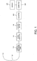
- FIG. 1 is a diagram illustrating a structure of a radiation dosimeter. This radiation dosimeter measures a dosage during radiotherapy performed using X-rays and ⁇ -rays.
- the scintillator 10 can be formed to have a small size of approximately 1 mm 2 x 0.1 mm, for example.
- the size of the scintillator 10 in the present embodiment is approximately a hundredth, which results in an increase in the spatial resolution of 100 times. Further, when a plurality of scintillators 10 are provided, it is possible to detect an ionizing radiation dose at a plurality of positions.
- an organic scintillator and particularly a plastic scintillator, is adopted as the scintillator 10, so that the ionizing radiation is converted to light with substantially no light emission occurring due to a photoelectric effect within the substance by means of the ionizing radiation.
- a scintillator containing a light element as a major component, similarly, substantially no light emission is caused by a photoelectric effect within the substance due to the ionizing radiation, as in the case of the plastic scintillator.
- a scintillator containing a light element as a major component whose emission delay time is 10 nanoseconds or less, is known, and the use of such a scintillator enables reliable separation of events and accurate counting of events.
- This substance forms a multiple quantum well structure including an organic layer formed of alkylamine as a barrier layer and an inorganic layer formed of lead halide as a well layer. Excitons confined in the well layer of this substance emit light by irradiation with radiation.
- a scintillator material Li 2 O-B 2 O 3 :Ce 3+ , is also known for a scintillator for neutrons.
- these scintillators are also capable of converting ionizing radiation to light with substantially no light emission caused by a photoelectric effect within the substances due to the ionizing radiation.
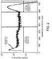
- FIG. 2 illustrates an energy spectrum of Cs-137 ⁇ -rays (661.6 keV) with a BGO scintillation detector.
- the scintillator 10 having a size of 10 mm ⁇ x 10 mm or less, preferably 1 mm ⁇ x 2 mm or less, more preferably 1 mm ⁇ x 1 mm or less, it is possible to increase the probability that Compton scattering electrons generated in the scintillator 10 itself are dissipated from the scintillator 10.
- the region (I) will present a distribution which depends on the shape and size of the scintillator 10, rather than a linear distribution.
- the region (I) assumes a distribution which depends on an interaction cross section between the electron and the scintillator 10, which is generally an exponential distribution. Accordingly, with a combination of this region (I) with the region (III) which also varies exponentially, computation of a dosage by counting ionizing radiation can be achieved.
- the size of the scintillator 10 it is possible to increase the probability that the Compton scattering electrons generated in the scintillator 10 itself are dissipated from the scintillator 10 to thereby change the region (I) to an exponential distribution, with substantially no light emission generated due to the photoelectric effect within the substance.
- the scintillator 10 is connected to an optical fiber 12 which transmits light that is converted from the ionizing radiation by the scintillator 10. It is also preferable that the optical fiber 12 is connected in a detachable manner by providing a connector in the middle thereof. This structure facilitates setting of the scintillator 10 at a desired position.
- the optical fiber 12 is connected to a photoelectron multiplier tube 14.
- the photoelectron multiplier tube 14 which is a photoelectric converter, converts light (a light signal) supplied from the optical fiber 12 into an electric signal in accordance with the light intensity.
- a signal amplifier 16 is connected to the photoelectron multiplier tube 14 for amplifying the electric signal supplied from the photoelectron multiplier tube 14.
- An output of the signal amplifier 16 is supplied to a discriminator 18, to which a threshold value is also input.
- the discriminator 18 discriminates, as an event, an electrical signal having a signal level which is a threshold value or greater, from other electrical signals input to the discriminator 18.
- the discriminator 18 aims at finally discriminating an electrical signal used for detecting an accurate dosage from electrical noise, and may therefore determine in comparison with detection performed by a high performance ionization chamber when specific ionizing radiation is incident.
- the discriminator 18 can be formed of a comparator and the like.
- the spectrum of adsorption energy in the scintillator 10 is represented by a pure exponential function, and if this assumption is established, no errors may be generated no matter what value is used for the threshold value.
- some errors will be generated by setting a certain threshold value. Specifically, as the threshold value becomes higher, the range of estimation is increased, resulting in a possibility of a greater error.
- counting should be performed more than the necessary number of times, leading to a possibility that the measuring device is saturated with too many pulses. It is therefore preferable that the threshold value is set to an appropriate value in consideration of the above.
- An output of the discriminator 18 is supplied to a counter 20, which counts the number of events discriminated by the discriminator 18.
- the counting result obtained by the counter 20 is supplied to a computer 22 where the count value of events is converted to a dosage, which is then displayed on the display 24.
- the computer 22 executes a program which is directly stored in a recording medium such as a hard disk within the computer 22, to perform the processing which will be described below.
- the program may be directly written in the computer 22, may be loaded from a CD, or may be supplied to the computer 22 through a communication line.
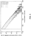
- the pulse height spectrum (a count value for each pulse height channel) of a light emission event of a plastic scintillator with respect to Ir-192 ⁇ -ray is a substantially exponential function.
- FIG. 3 illustrates results in a case where the distance to a ray source is shifted by 1 cm, from 3 cm to 7 cm. In each result, as the signal level (pulse height) of the light emission event becomes higher, the count value of the light emission event is exponentially decreased accordingly.
- a plastic scintillator BC490 manufactured by Saint-Gobain CDJ K.K. is used as the scintillator 10.
- "a" and "b” are constants defined based on the relationship shown in FIG. 3 .
- D W ⁇ en ⁇ W ⁇ en ⁇ Sc C total b ⁇ a ⁇ t b 2 exp ⁇ b E 0 ⁇ 1
- ( ⁇ en / ⁇ ) [m 2 ⁇ kg -1 ] represents a mass energy transfer coefficient, and such a coefficient with subscript "Sc" indicates that of the scintillator 10 and the coefficient with subscript "W” indicates that of water. More specifically, in the first term of the right side of the formula (9), the dosage in the scintillator 10 is converted to a water absorbed dose.
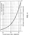
- FIG. 4 illustrates results of measuring a relationship (absorbed dose rate distribution) between a distance from a ray source and an absorbed dose rate ([cGy/min]) in water phantom in which an Ir-192 source for brachytherapy is employed, by using the device according to the present embodiment.
- the Monte Carlo N-Particle Transport Code (MCNP-4C) was used for comparison with the measurement results.
- the measurement results which match the MCNP-4C code very precisely could be obtained with respect to changes in dosages over two digits or more. Also, such a measurement over a wide range as shown is one of the features of the present embodiment.
- FIG. 5 illustrates a comparison between the dosage measurement of the present embodiment and the conventional dosage measurement.
- the dosage is obtained from the number of events equal to a threshold value or greater.
- highly precise detection can be achieved in a relatively simple manner concerning the scintillator 10 and a processing circuit thereof.
- a plastic scintillator which emits green light (about 490 nm) is used as the scintillator 10.
- the wavelength spectrum of the Cherenkov light expands to near the red light region (600 nm) depending on its intensity, and has a sufficient intensity even in the blue light region (about 420 nm).
- This nature is utilized to split light using a beam splitter which separates light, with the wavelength of 455 nm being used as a border, so that the Cherenkov light is determined when light of 455 nm or less and light of 455 nm or more is measured simultaneously and a signal is determined when only light of 455 nm or more is measured.
- FIG. 6 illustrates an example structure for this case.
- Light emitted by the scintillator 10 is transmitted, via the optical fiber 12, to the beam splitter 30 where the light is divided into light of 455 nm or less and light of 455 nm or more.
- the light of 455 nm or less is directed to a photoelectron multiplier tube 14-1, a signal amplifier 16-1, and a discriminator 18-1, where an event is detected, and a signal concerning the event which is detected is supplied to a comparison operator 32.
- the light of 455 nm or more is directed to a photoelectron multiplier tube 14-2, a signal amplifier 16-2, and a discriminator 18-2, where an event is detected, and a signal concerning the event which is detected is supplied to the comparison operator 32.
- the comparison operator 32 is formed by an anti-coincidence counter circuit. More specifically, the comparison operator 32 outputs no count signals when signals are supplied from both discriminators 18-1 and 18-2 at the same timing and outputs a count signal only when a necessary signal is supplied. It is assumed, for example, that, of a blue light emission signal B and a green light emission signal G, the light emission signal G is necessary. When only the G signal is supplied to the comparison operator 32 without the B signal being supplied simultaneously, the comparison operator 32 outputs a count signal. When only the B signal is supplied to the comparison operator 32, without the G signal being supplied simultaneously, or when the B signal and the G signal are input simultaneously, the comparison operator 32 does not output a count signal.
- a gate is formed by the B signal to allow the G signal to pass only when B signal is not present.
- the comparison operator 32 based on the signals supplied from the both discriminators 18-1 and 18-2, removes a signal of the Cherenkov light and outputs a count signal. Accordingly, the counter 20 can count the count signals supplied from the comparison operator 32, while eliminating the effects of the Cherenkov light.
- the light of 455 nm or less and the light of 455 nm or more separated by the beam splitter 30 does not necessarily have the same level, it is preferable to adopt different threshold values for the discriminators 18-1 and 18-2, so that appropriate determination can be performed.
- an amount of light emission at the scintillator 10 is converted to an electric current value (voltage value) by the photoelectron multiplier tube 14, and then the discriminator 18 is employed to discriminate only events with a threshold light emission amount or more, and the counter 20 further counts the number of events.
- the photoelectron multiplier tube 14, the discriminator 18, and the counter 20 are inexpensive, and therefore the present embodiment does not require an expensive micro ammeter as required in JP 2004-526155 A .
- the scintillator 10 need not have a large size and a smaller scintillator is preferable. More specifically, with the use of a small scintillator 10, the spatial resolution concerning a measurement value can be increased. For example, while a scintillator of 1 mm ⁇ x 10 mm is used in JP 2004-526155 A , a hemisphere scintillator having a diameter of about 1 mm, which is a scintillator about a thirtieth of the conventional scintillator, is used in the present embodiment. Consequently, the spatial resolution by measurement results is 20 times that of the conventional scintillator. It is therefore possible to detect and measure ⁇ -rays within a living body and also to accurately measure the dosage during radiotherapy, which could only be measured based on vague estimation in the conventional technology.
- the structure of a device can be simplified as described above, it is easy to provide a multi-channel structure in which a large number of scintillators 10 are provided to detect the radiation doses at a large number of positions.
Landscapes
- Health & Medical Sciences (AREA)
- Life Sciences & Earth Sciences (AREA)
- Biomedical Technology (AREA)
- General Physics & Mathematics (AREA)
- High Energy & Nuclear Physics (AREA)
- Molecular Biology (AREA)
- Spectroscopy & Molecular Physics (AREA)
- Engineering & Computer Science (AREA)
- Physics & Mathematics (AREA)
- Pathology (AREA)
- Nuclear Medicine, Radiotherapy & Molecular Imaging (AREA)
- Radiology & Medical Imaging (AREA)
- Animal Behavior & Ethology (AREA)
- General Health & Medical Sciences (AREA)
- Public Health (AREA)
- Veterinary Medicine (AREA)
- Measurement Of Radiation (AREA)
Claims (7)
- Dosimètre de rayonnement comprenant :un scintillateur (10) qui émet de la lumière par un rayonnement ionisant incident,un convertisseur photo électrique (14) qui converti la lumière émise en sortie du scintillateur en un courant électrique,un compteur (20) qui compte le nombre d'événements en sortie du convertisseur photo électrique ayant une intensité égale ou supérieure à une valeur de seuil prédéfinie,une unité de dosage (22) réalisée pour convertir la valeur de comptage délivrée par le compteur en une dose pour obtenir la dose, à partir d'une relation dans laquelle la fréquence d'apparition de chaque évènement diminue de manière exponentielle lorsque l'intensité de la lumière de l'événement augmente,caractérisé en ce quel'unité de dosage (22) est réalisée pour permettre de calculer une dose DSc dans le scintillateur à partir de la formule suivante :

- Dosimètre de rayonnement conforme à la revendication 1,
constitué par un scintillateur organique plastique. - Dosimètre de rayonnement conforme à la revendication 1,
renfermant en tant que composant principal un élément luminescent ayant un temps de décroissance d'émission de 10 nano secondes ou moins. - Dosimètre de rayonnement conforme à la revendication 1,
ayant un volume égal à 1 mm3 ou moins. - Dosimètre de rayonnement conforme à la revendication 1,
dans lequel la lumière de Cherenkov et la lumière émise par le scintillateur sont différenciées en déterminant si l'émission de lumière à plusieurs longueurs d'ondes différentes apparait simultanément ou si seule apparait une émission de lumière à une seule longueur d'ondes spécifique, et le comptage est effectué de sorte que l'émission de lumière autre que l'émission de lumière par le scintillateur soit supprimée. - Programme de dosage d'un rayonnement permettant de compter une dose au moyen d'un scintillateur, ce programme permettant à un ordinateur d'exécuter un procédé comprenant des étapes consistant à :se procurer une valeur de comptage obtenue en comptant un nombre d'événements ayant une intensité égale ou supérieure à une valeur de seuil prédéfinie d'un signal électrique qui est converti en un courant électrique provenant de la lumière délivrée en sortie par le scintillateur qui émet de la lumière par un rayonnement ionisant incident,convertir la valeur de comptage fournie en une dose à partir d'une relation dans laquelle la fréquence d'apparition de chaque événement diminue de façon exponentielle lorsque l'intensité de la lumière de l'événement augmente, de façon à obtenir la dose,caractérisé en ce quela relation qui est pré-enregistrée est basée sur la formule suivante :

- Support d'enregistrement d'un programme de calcul d'une dose de rayonnement permettant de calculer une dose au moyen d'un scintillateur, ce programme permettant à un ordinateur de mettre en oeuvre un procédé comprenant des étapes constant à :se procurer une valeur de comptage obtenue en comptant un nombre d'événements ayant une intensité égale ou supérieure à une valeur de seuil prédéfinie, d'un signal électrique qui est converti en un courant électrique provenant de la lumière délivrée en sortie par le scintillateur qui émet de la lumière par un rayonnement ionisant incident, etconvertir la valeur de comptage fournie en une dose à partir d'une relation dans laquelle la fréquence d'apparition de chaque événement diminue de manière exponentielle lorsque l'intensité de la lumière de l'événement augmente, de façon à obtenir la dose,caractérisé en ce quela relation qui est pré-enregistrée est basée sur la formule suivante :

Applications Claiming Priority (2)
| Application Number | Priority Date | Filing Date | Title |
|---|---|---|---|
| JP2006261241 | 2006-09-26 | ||
| PCT/JP2007/068675 WO2008038662A1 (fr) | 2006-09-26 | 2007-09-26 | Dosimètre de radiations et programme de calcul de doses de radiations |
Publications (3)
| Publication Number | Publication Date |
|---|---|
| EP2077457A1 EP2077457A1 (fr) | 2009-07-08 |
| EP2077457A4 EP2077457A4 (fr) | 2016-08-17 |
| EP2077457B1 true EP2077457B1 (fr) | 2018-11-14 |
Family
ID=39230098
Family Applications (1)
| Application Number | Title | Priority Date | Filing Date |
|---|---|---|---|
| EP07807890.4A Not-in-force EP2077457B1 (fr) | 2006-09-26 | 2007-09-26 | Dosimètre de radiations et programme de calcul de doses de radiations |
Country Status (4)
| Country | Link |
|---|---|
| US (1) | US8044357B2 (fr) |
| EP (1) | EP2077457B1 (fr) |
| JP (1) | JP4766407B2 (fr) |
| WO (1) | WO2008038662A1 (fr) |
Families Citing this family (18)
| Publication number | Priority date | Publication date | Assignee | Title |
|---|---|---|---|---|
| US9155909B2 (en) | 2009-03-24 | 2015-10-13 | National University Corporation Hokkaido University | Radiation therapy apparatus |
| US8604440B2 (en) * | 2010-03-09 | 2013-12-10 | The University Of Chicago | Use of flat panel microchannel photomultipliers in sampling calorimeters with timing |
| US9000401B2 (en) | 2010-07-07 | 2015-04-07 | Institut National D'optique | Fiber optic radiochromic dosimeter probe and method to make the same |
| US20120292517A1 (en) * | 2011-05-19 | 2012-11-22 | Washington University | Real-time imaging dosimeter systems and method |
| WO2012159201A1 (fr) * | 2011-05-24 | 2012-11-29 | UNIVERSITé LAVAL | Procédés et appareils pour détecteur à scintillation multipoint à position optiquement codée faisant appel à un seul guide de lumière de collecte |
| US8658978B2 (en) | 2011-12-29 | 2014-02-25 | Raytheon Company | Methods and apparatus for a radiation monitor |
| US9958402B2 (en) * | 2012-02-23 | 2018-05-01 | Steven M. Ebstein | Dosimetric scintillating screen detector for charged particle radiotherapy quality assurance (QA) |
| JP5791546B2 (ja) * | 2012-02-29 | 2015-10-07 | 株式会社日立製作所 | 放射線計測装置の較正方法及び粒子線治療装置 |
| WO2013184204A2 (fr) | 2012-03-22 | 2013-12-12 | Duke University | Scintillateurs à base de nanocristaux ayant une réponse linéaire et leurs procédés d'utilisation |
| CN102981180B (zh) * | 2012-12-12 | 2015-08-26 | 中国科学院国家天文台 | 水切伦科夫光高能粒子探测器 |
| CN103018763B (zh) * | 2012-12-12 | 2015-08-26 | 中国科学院国家天文台 | gamma射线与宇宙线的探测装置与方法 |
| JP2014241543A (ja) * | 2013-06-12 | 2014-12-25 | 株式会社東芝 | 光検出装置およびct装置 |
| CN105849536B (zh) * | 2013-11-08 | 2021-07-30 | 普拉德研究及开发股份有限公司 | 利用谱去卷积进行谱分析 |
| JP6452425B2 (ja) * | 2014-12-11 | 2019-01-16 | 株式会社日立製作所 | 放射線モニタ |
| JP6730702B2 (ja) * | 2015-02-12 | 2020-07-29 | 国立大学法人北海道大学 | シンチレータ及びこれを用いた放射線線量計 |
| WO2017081324A1 (fr) * | 2015-11-12 | 2017-05-18 | Centre National De La Recherche Scientifique | Dispositif de détermination d'une dose déposée et procédé associé |
| JP6817162B2 (ja) * | 2017-07-07 | 2021-01-20 | 株式会社日立製作所 | 放射線モニタ装置および放射線治療装置、ならびに放射線のモニタ方法 |
| CN109975855B (zh) * | 2019-04-02 | 2023-09-19 | 东华理工大学 | 一种基于蓝牙技术的宽量程智能X-γ剂量率仪装置 |
Family Cites Families (8)
| Publication number | Priority date | Publication date | Assignee | Title |
|---|---|---|---|---|
| JPS51124981A (en) * | 1975-04-24 | 1976-10-30 | Japan Atom Energy Res Inst | A gamma ray scintillation detector |
| JP2001056381A (ja) | 1999-08-20 | 2001-02-27 | Mitsubishi Electric Corp | 局所線量計及びそれを用いた医療装置 |
| US6320935B1 (en) * | 2000-02-28 | 2001-11-20 | X-Technologies, Ltd. | Dosimeter for a miniature energy transducer for emitting X-ray radiation |
| FR2822239B1 (fr) | 2001-03-15 | 2003-09-26 | Centre Nat Rech Scient | Procede de mesure de dose d'irradiation |
| JP2003194953A (ja) * | 2001-12-25 | 2003-07-09 | Toden Kogyo Co Ltd | 放射線測定プログラム及び放射線測定器 |
| CN1481756A (zh) * | 2002-08-14 | 2004-03-17 | ��ʽ���綫֥ | 集中照射型放疗设备 |
| JP2004191327A (ja) | 2002-12-13 | 2004-07-08 | Natl Inst Of Radiological Sciences | ガンマ線検出器 |
| WO2005008287A1 (fr) | 2003-07-18 | 2005-01-27 | Toudai Tlo, Ltd. | Dispositif de surveillance de flux de neutrons thermiques |
-
2007
- 2007-09-26 EP EP07807890.4A patent/EP2077457B1/fr not_active Not-in-force
- 2007-09-26 US US12/443,101 patent/US8044357B2/en active Active
- 2007-09-26 WO PCT/JP2007/068675 patent/WO2008038662A1/fr not_active Ceased
- 2007-09-26 JP JP2008536391A patent/JP4766407B2/ja active Active
Non-Patent Citations (1)
| Title |
|---|
| None * |
Also Published As
| Publication number | Publication date |
|---|---|
| US8044357B2 (en) | 2011-10-25 |
| WO2008038662A1 (fr) | 2008-04-03 |
| JPWO2008038662A1 (ja) | 2010-01-28 |
| EP2077457A4 (fr) | 2016-08-17 |
| US20100038547A1 (en) | 2010-02-18 |
| JP4766407B2 (ja) | 2011-09-07 |
| EP2077457A1 (fr) | 2009-07-08 |
Similar Documents
| Publication | Publication Date | Title |
|---|---|---|
| EP2077457B1 (fr) | Dosimètre de radiations et programme de calcul de doses de radiations | |
| US6876711B2 (en) | Neutron detector utilizing sol-gel absorber and activation disk | |
| JP5027124B2 (ja) | パルス波形分析による単一トランスデューサ内同時発生放射線の検出のための方法及び装置 | |
| RU2501040C2 (ru) | Устройство и способ для детектирования нейтронов с помощью поглощающих нейтроны калориметрических гамма-детекторов | |
| US9244178B2 (en) | Method for determining the irradiation dose deposited in a scintillator by ionising radiation and associated device | |
| RU2502088C2 (ru) | Устройство и способ для детектирования нейтронов посредством калориметрии на основе гамма-захвата | |
| US11163076B2 (en) | Method for the detection of neutrons with scintillation detectors used for gamma ray spectroscopy | |
| US10386499B2 (en) | Device for determining a deposited dose and associated method | |
| RU2189057C2 (ru) | Сцинтилляционный детектор нейтронного и гамма-излучения | |
| RU2143711C1 (ru) | Детектор для регистрации ионизирующих излучений | |
| CN108535758B (zh) | 一种脉冲形状甄别算法 | |
| JP4893950B2 (ja) | 放射能絶対測定方法、放射線検出器集合体の検出効率決定方法、及び、放射線測定装置の校正方法 | |
| Farsoni et al. | A system for simultaneous beta and gamma spectroscopy | |
| JP4061367B2 (ja) | ZnS(Ag)シンチレーション検出器 | |
| Tsutsumi et al. | LaCl3 (Ce) scintillation detector applications for environmental gamma-ray measurements of low to high dose rates | |
| Farsoni et al. | MCNP analysis of a multilayer phoswich detector for β-particle dosimetry and spectroscopy | |
| Del Guerra et al. | Radiation measurement | |
| JP2012242369A (ja) | 放射線検出器 | |
| Urbański et al. | Review of X-ray detection systems | |
| Tancioni et al. | Gamma dose rate monitoring using a Silicon Photomultiplier-based plastic scintillation detector | |
| JP7750528B2 (ja) | 信号処理システム、陽電子放射断層撮影装置及び陽電子放射断層撮影方法 | |
| JP7427562B2 (ja) | 放射線測定装置および放射線測定方法 | |
| RU119131U1 (ru) | Сцинтилляционный детектор электронов и бета-излучения | |
| DeVol et al. | Alpha/beta (gamma ray) discrimination and spillover quantification with a BaF2 scintillator | |
| Sh et al. | FEATURES OF QUANTUM GAMMA SPECTROMETERS AND ERRORS IN THE OPERATION OF DETECTORS |
Legal Events
| Date | Code | Title | Description |
|---|---|---|---|
| PUAI | Public reference made under article 153(3) epc to a published international application that has entered the european phase |
Free format text: ORIGINAL CODE: 0009012 |
|
| 17P | Request for examination filed |
Effective date: 20090416 |
|
| AK | Designated contracting states |
Kind code of ref document: A1 Designated state(s): AT BE BG CH CY CZ DE DK EE ES FI FR GB GR HU IE IS IT LI LT LU LV MC MT NL PL PT RO SE SI SK TR |
|
| DAX | Request for extension of the european patent (deleted) | ||
| RA4 | Supplementary search report drawn up and despatched (corrected) |
Effective date: 20160715 |
|
| RIC1 | Information provided on ipc code assigned before grant |
Ipc: A61N 5/10 20060101ALI20160712BHEP Ipc: G01T 1/203 20060101ALI20160712BHEP Ipc: G01T 1/02 20060101ALI20160712BHEP Ipc: G01T 1/20 20060101AFI20160712BHEP |
|
| GRAP | Despatch of communication of intention to grant a patent |
Free format text: ORIGINAL CODE: EPIDOSNIGR1 |
|
| STAA | Information on the status of an ep patent application or granted ep patent |
Free format text: STATUS: GRANT OF PATENT IS INTENDED |
|
| INTG | Intention to grant announced |
Effective date: 20180605 |
|
| GRAS | Grant fee paid |
Free format text: ORIGINAL CODE: EPIDOSNIGR3 |
|
| GRAA | (expected) grant |
Free format text: ORIGINAL CODE: 0009210 |
|
| STAA | Information on the status of an ep patent application or granted ep patent |
Free format text: STATUS: THE PATENT HAS BEEN GRANTED |
|
| RAP1 | Party data changed (applicant data changed or rights of an application transferred) |
Owner name: NATIONAL UNIVERSITY CORPORATION HOKKAIDO UNIVERSIT |
|
| RIN1 | Information on inventor provided before grant (corrected) |
Inventor name: ISHIKAWA, MASAYORI |
|
| AK | Designated contracting states |
Kind code of ref document: B1 Designated state(s): AT BE BG CH CY CZ DE DK EE ES FI FR GB GR HU IE IS IT LI LT LU LV MC MT NL PL PT RO SE SI SK TR |
|
| REG | Reference to a national code |
Ref country code: GB Ref legal event code: FG4D |
|
| REG | Reference to a national code |
Ref country code: CH Ref legal event code: EP Ref country code: AT Ref legal event code: REF Ref document number: 1065488 Country of ref document: AT Kind code of ref document: T Effective date: 20181115 |
|
| REG | Reference to a national code |
Ref country code: DE Ref legal event code: R096 Ref document number: 602007056833 Country of ref document: DE |
|
| REG | Reference to a national code |
Ref country code: IE Ref legal event code: FG4D |
|
| REG | Reference to a national code |
Ref country code: NL Ref legal event code: MP Effective date: 20181114 |
|
| REG | Reference to a national code |
Ref country code: LT Ref legal event code: MG4D |
|
| REG | Reference to a national code |
Ref country code: AT Ref legal event code: MK05 Ref document number: 1065488 Country of ref document: AT Kind code of ref document: T Effective date: 20181114 |
|
| PG25 | Lapsed in a contracting state [announced via postgrant information from national office to epo] |
Ref country code: BG Free format text: LAPSE BECAUSE OF FAILURE TO SUBMIT A TRANSLATION OF THE DESCRIPTION OR TO PAY THE FEE WITHIN THE PRESCRIBED TIME-LIMIT Effective date: 20190214 Ref country code: AT Free format text: LAPSE BECAUSE OF FAILURE TO SUBMIT A TRANSLATION OF THE DESCRIPTION OR TO PAY THE FEE WITHIN THE PRESCRIBED TIME-LIMIT Effective date: 20181114 Ref country code: LV Free format text: LAPSE BECAUSE OF FAILURE TO SUBMIT A TRANSLATION OF THE DESCRIPTION OR TO PAY THE FEE WITHIN THE PRESCRIBED TIME-LIMIT Effective date: 20181114 Ref country code: FI Free format text: LAPSE BECAUSE OF FAILURE TO SUBMIT A TRANSLATION OF THE DESCRIPTION OR TO PAY THE FEE WITHIN THE PRESCRIBED TIME-LIMIT Effective date: 20181114 Ref country code: IS Free format text: LAPSE BECAUSE OF FAILURE TO SUBMIT A TRANSLATION OF THE DESCRIPTION OR TO PAY THE FEE WITHIN THE PRESCRIBED TIME-LIMIT Effective date: 20190314 Ref country code: LT Free format text: LAPSE BECAUSE OF FAILURE TO SUBMIT A TRANSLATION OF THE DESCRIPTION OR TO PAY THE FEE WITHIN THE PRESCRIBED TIME-LIMIT Effective date: 20181114 Ref country code: ES Free format text: LAPSE BECAUSE OF FAILURE TO SUBMIT A TRANSLATION OF THE DESCRIPTION OR TO PAY THE FEE WITHIN THE PRESCRIBED TIME-LIMIT Effective date: 20181114 |
|
| PG25 | Lapsed in a contracting state [announced via postgrant information from national office to epo] |
Ref country code: GR Free format text: LAPSE BECAUSE OF FAILURE TO SUBMIT A TRANSLATION OF THE DESCRIPTION OR TO PAY THE FEE WITHIN THE PRESCRIBED TIME-LIMIT Effective date: 20190215 Ref country code: PT Free format text: LAPSE BECAUSE OF FAILURE TO SUBMIT A TRANSLATION OF THE DESCRIPTION OR TO PAY THE FEE WITHIN THE PRESCRIBED TIME-LIMIT Effective date: 20190314 Ref country code: NL Free format text: LAPSE BECAUSE OF FAILURE TO SUBMIT A TRANSLATION OF THE DESCRIPTION OR TO PAY THE FEE WITHIN THE PRESCRIBED TIME-LIMIT Effective date: 20181114 Ref country code: SE Free format text: LAPSE BECAUSE OF FAILURE TO SUBMIT A TRANSLATION OF THE DESCRIPTION OR TO PAY THE FEE WITHIN THE PRESCRIBED TIME-LIMIT Effective date: 20181114 |
|
| PG25 | Lapsed in a contracting state [announced via postgrant information from national office to epo] |
Ref country code: PL Free format text: LAPSE BECAUSE OF FAILURE TO SUBMIT A TRANSLATION OF THE DESCRIPTION OR TO PAY THE FEE WITHIN THE PRESCRIBED TIME-LIMIT Effective date: 20181114 Ref country code: CZ Free format text: LAPSE BECAUSE OF FAILURE TO SUBMIT A TRANSLATION OF THE DESCRIPTION OR TO PAY THE FEE WITHIN THE PRESCRIBED TIME-LIMIT Effective date: 20181114 Ref country code: IT Free format text: LAPSE BECAUSE OF FAILURE TO SUBMIT A TRANSLATION OF THE DESCRIPTION OR TO PAY THE FEE WITHIN THE PRESCRIBED TIME-LIMIT Effective date: 20181114 Ref country code: DK Free format text: LAPSE BECAUSE OF FAILURE TO SUBMIT A TRANSLATION OF THE DESCRIPTION OR TO PAY THE FEE WITHIN THE PRESCRIBED TIME-LIMIT Effective date: 20181114 |
|
| REG | Reference to a national code |
Ref country code: DE Ref legal event code: R097 Ref document number: 602007056833 Country of ref document: DE |
|
| PG25 | Lapsed in a contracting state [announced via postgrant information from national office to epo] |
Ref country code: EE Free format text: LAPSE BECAUSE OF FAILURE TO SUBMIT A TRANSLATION OF THE DESCRIPTION OR TO PAY THE FEE WITHIN THE PRESCRIBED TIME-LIMIT Effective date: 20181114 Ref country code: SK Free format text: LAPSE BECAUSE OF FAILURE TO SUBMIT A TRANSLATION OF THE DESCRIPTION OR TO PAY THE FEE WITHIN THE PRESCRIBED TIME-LIMIT Effective date: 20181114 Ref country code: RO Free format text: LAPSE BECAUSE OF FAILURE TO SUBMIT A TRANSLATION OF THE DESCRIPTION OR TO PAY THE FEE WITHIN THE PRESCRIBED TIME-LIMIT Effective date: 20181114 |
|
| PLBE | No opposition filed within time limit |
Free format text: ORIGINAL CODE: 0009261 |
|
| STAA | Information on the status of an ep patent application or granted ep patent |
Free format text: STATUS: NO OPPOSITION FILED WITHIN TIME LIMIT |
|
| 26N | No opposition filed |
Effective date: 20190815 |
|
| PG25 | Lapsed in a contracting state [announced via postgrant information from national office to epo] |
Ref country code: SI Free format text: LAPSE BECAUSE OF FAILURE TO SUBMIT A TRANSLATION OF THE DESCRIPTION OR TO PAY THE FEE WITHIN THE PRESCRIBED TIME-LIMIT Effective date: 20181114 |
|
| PG25 | Lapsed in a contracting state [announced via postgrant information from national office to epo] |
Ref country code: TR Free format text: LAPSE BECAUSE OF FAILURE TO SUBMIT A TRANSLATION OF THE DESCRIPTION OR TO PAY THE FEE WITHIN THE PRESCRIBED TIME-LIMIT Effective date: 20181114 |
|
| PG25 | Lapsed in a contracting state [announced via postgrant information from national office to epo] |
Ref country code: MC Free format text: LAPSE BECAUSE OF FAILURE TO SUBMIT A TRANSLATION OF THE DESCRIPTION OR TO PAY THE FEE WITHIN THE PRESCRIBED TIME-LIMIT Effective date: 20181114 |
|
| REG | Reference to a national code |
Ref country code: CH Ref legal event code: PL |
|
| PG25 | Lapsed in a contracting state [announced via postgrant information from national office to epo] |
Ref country code: CH Free format text: LAPSE BECAUSE OF NON-PAYMENT OF DUE FEES Effective date: 20190930 Ref country code: LU Free format text: LAPSE BECAUSE OF NON-PAYMENT OF DUE FEES Effective date: 20190926 Ref country code: IE Free format text: LAPSE BECAUSE OF NON-PAYMENT OF DUE FEES Effective date: 20190926 Ref country code: LI Free format text: LAPSE BECAUSE OF NON-PAYMENT OF DUE FEES Effective date: 20190930 |
|
| REG | Reference to a national code |
Ref country code: BE Ref legal event code: MM Effective date: 20190930 |
|
| PG25 | Lapsed in a contracting state [announced via postgrant information from national office to epo] |
Ref country code: BE Free format text: LAPSE BECAUSE OF NON-PAYMENT OF DUE FEES Effective date: 20190930 |
|
| PG25 | Lapsed in a contracting state [announced via postgrant information from national office to epo] |
Ref country code: CY Free format text: LAPSE BECAUSE OF FAILURE TO SUBMIT A TRANSLATION OF THE DESCRIPTION OR TO PAY THE FEE WITHIN THE PRESCRIBED TIME-LIMIT Effective date: 20181114 |
|
| PG25 | Lapsed in a contracting state [announced via postgrant information from national office to epo] |
Ref country code: HU Free format text: LAPSE BECAUSE OF FAILURE TO SUBMIT A TRANSLATION OF THE DESCRIPTION OR TO PAY THE FEE WITHIN THE PRESCRIBED TIME-LIMIT; INVALID AB INITIO Effective date: 20070926 Ref country code: MT Free format text: LAPSE BECAUSE OF FAILURE TO SUBMIT A TRANSLATION OF THE DESCRIPTION OR TO PAY THE FEE WITHIN THE PRESCRIBED TIME-LIMIT Effective date: 20181114 |
|
| P01 | Opt-out of the competence of the unified patent court (upc) registered |
Effective date: 20230524 |
|
| PGFP | Annual fee paid to national office [announced via postgrant information from national office to epo] |
Ref country code: GB Payment date: 20230920 Year of fee payment: 17 |
|
| PGFP | Annual fee paid to national office [announced via postgrant information from national office to epo] |
Ref country code: FR Payment date: 20230928 Year of fee payment: 17 Ref country code: DE Payment date: 20230920 Year of fee payment: 17 |
|
| REG | Reference to a national code |
Ref country code: DE Ref legal event code: R119 Ref document number: 602007056833 Country of ref document: DE |
|
| GBPC | Gb: european patent ceased through non-payment of renewal fee |
Effective date: 20240926 |
|
| PG25 | Lapsed in a contracting state [announced via postgrant information from national office to epo] |
Ref country code: DE Free format text: LAPSE BECAUSE OF NON-PAYMENT OF DUE FEES Effective date: 20250401 |
|
| PG25 | Lapsed in a contracting state [announced via postgrant information from national office to epo] |
Ref country code: GB Free format text: LAPSE BECAUSE OF NON-PAYMENT OF DUE FEES Effective date: 20240926 |
|
| PG25 | Lapsed in a contracting state [announced via postgrant information from national office to epo] |
Ref country code: FR Free format text: LAPSE BECAUSE OF NON-PAYMENT OF DUE FEES Effective date: 20240930 |