EP2077597B1 - Empilement de piles à combustible ayant une distribution de température homgène le long de l'axe d'empilement - Google Patents
Empilement de piles à combustible ayant une distribution de température homgène le long de l'axe d'empilement Download PDFInfo
- Publication number
- EP2077597B1 EP2077597B1 EP07828467.6A EP07828467A EP2077597B1 EP 2077597 B1 EP2077597 B1 EP 2077597B1 EP 07828467 A EP07828467 A EP 07828467A EP 2077597 B1 EP2077597 B1 EP 2077597B1
- Authority
- EP
- European Patent Office
- Prior art keywords
- fuel cell
- fuel cells
- fuel
- cell stack
- oxygen
- Prior art date
- Legal status (The legal status is an assumption and is not a legal conclusion. Google has not performed a legal analysis and makes no representation as to the accuracy of the status listed.)
- Ceased
Links
Images


Classifications
-
- H—ELECTRICITY
- H01—ELECTRIC ELEMENTS
- H01M—PROCESSES OR MEANS, e.g. BATTERIES, FOR THE DIRECT CONVERSION OF CHEMICAL ENERGY INTO ELECTRICAL ENERGY
- H01M8/00—Fuel cells; Manufacture thereof
- H01M8/04—Auxiliary arrangements, e.g. for control of pressure or for circulation of fluids
- H01M8/04007—Auxiliary arrangements, e.g. for control of pressure or for circulation of fluids related to heat exchange
-
- H—ELECTRICITY
- H01—ELECTRIC ELEMENTS
- H01M—PROCESSES OR MEANS, e.g. BATTERIES, FOR THE DIRECT CONVERSION OF CHEMICAL ENERGY INTO ELECTRICAL ENERGY
- H01M8/00—Fuel cells; Manufacture thereof
- H01M8/02—Details
- H01M8/0202—Collectors; Separators, e.g. bipolar separators; Interconnectors
- H01M8/0258—Collectors; Separators, e.g. bipolar separators; Interconnectors characterised by the configuration of channels, e.g. by the flow field of the reactant or coolant
-
- H—ELECTRICITY
- H01—ELECTRIC ELEMENTS
- H01M—PROCESSES OR MEANS, e.g. BATTERIES, FOR THE DIRECT CONVERSION OF CHEMICAL ENERGY INTO ELECTRICAL ENERGY
- H01M8/00—Fuel cells; Manufacture thereof
- H01M8/02—Details
- H01M8/0271—Sealing or supporting means around electrodes, matrices or membranes
-
- H—ELECTRICITY
- H01—ELECTRIC ELEMENTS
- H01M—PROCESSES OR MEANS, e.g. BATTERIES, FOR THE DIRECT CONVERSION OF CHEMICAL ENERGY INTO ELECTRICAL ENERGY
- H01M8/00—Fuel cells; Manufacture thereof
- H01M8/02—Details
- H01M8/0297—Arrangements for joining electrodes, reservoir layers, heat exchange units or bipolar separators to each other
-
- H—ELECTRICITY
- H01—ELECTRIC ELEMENTS
- H01M—PROCESSES OR MEANS, e.g. BATTERIES, FOR THE DIRECT CONVERSION OF CHEMICAL ENERGY INTO ELECTRICAL ENERGY
- H01M8/00—Fuel cells; Manufacture thereof
- H01M8/04—Auxiliary arrangements, e.g. for control of pressure or for circulation of fluids
- H01M8/04007—Auxiliary arrangements, e.g. for control of pressure or for circulation of fluids related to heat exchange
- H01M8/04067—Heat exchange or temperature measuring elements, thermal insulation, e.g. heat pipes, heat pumps, fins
-
- H—ELECTRICITY
- H01—ELECTRIC ELEMENTS
- H01M—PROCESSES OR MEANS, e.g. BATTERIES, FOR THE DIRECT CONVERSION OF CHEMICAL ENERGY INTO ELECTRICAL ENERGY
- H01M8/00—Fuel cells; Manufacture thereof
- H01M8/24—Grouping of fuel cells, e.g. stacking of fuel cells
- H01M8/241—Grouping of fuel cells, e.g. stacking of fuel cells with solid or matrix-supported electrolytes
-
- H—ELECTRICITY
- H01—ELECTRIC ELEMENTS
- H01M—PROCESSES OR MEANS, e.g. BATTERIES, FOR THE DIRECT CONVERSION OF CHEMICAL ENERGY INTO ELECTRICAL ENERGY
- H01M8/00—Fuel cells; Manufacture thereof
- H01M8/24—Grouping of fuel cells, e.g. stacking of fuel cells
- H01M8/241—Grouping of fuel cells, e.g. stacking of fuel cells with solid or matrix-supported electrolytes
- H01M8/2425—High-temperature cells with solid electrolytes
-
- H—ELECTRICITY
- H01—ELECTRIC ELEMENTS
- H01M—PROCESSES OR MEANS, e.g. BATTERIES, FOR THE DIRECT CONVERSION OF CHEMICAL ENERGY INTO ELECTRICAL ENERGY
- H01M8/00—Fuel cells; Manufacture thereof
- H01M8/24—Grouping of fuel cells, e.g. stacking of fuel cells
- H01M8/2457—Grouping of fuel cells, e.g. stacking of fuel cells with both reactants being gaseous or vaporised
-
- H—ELECTRICITY
- H01—ELECTRIC ELEMENTS
- H01M—PROCESSES OR MEANS, e.g. BATTERIES, FOR THE DIRECT CONVERSION OF CHEMICAL ENERGY INTO ELECTRICAL ENERGY
- H01M8/00—Fuel cells; Manufacture thereof
- H01M8/24—Grouping of fuel cells, e.g. stacking of fuel cells
- H01M8/2465—Details of groupings of fuel cells
-
- H—ELECTRICITY
- H01—ELECTRIC ELEMENTS
- H01M—PROCESSES OR MEANS, e.g. BATTERIES, FOR THE DIRECT CONVERSION OF CHEMICAL ENERGY INTO ELECTRICAL ENERGY
- H01M8/00—Fuel cells; Manufacture thereof
- H01M8/24—Grouping of fuel cells, e.g. stacking of fuel cells
- H01M8/2465—Details of groupings of fuel cells
- H01M8/2483—Details of groupings of fuel cells characterised by internal manifolds
-
- H—ELECTRICITY
- H01—ELECTRIC ELEMENTS
- H01M—PROCESSES OR MEANS, e.g. BATTERIES, FOR THE DIRECT CONVERSION OF CHEMICAL ENERGY INTO ELECTRICAL ENERGY
- H01M8/00—Fuel cells; Manufacture thereof
- H01M8/24—Grouping of fuel cells, e.g. stacking of fuel cells
- H01M8/249—Grouping of fuel cells, e.g. stacking of fuel cells comprising two or more groupings of fuel cells, e.g. modular assemblies
-
- H—ELECTRICITY
- H01—ELECTRIC ELEMENTS
- H01M—PROCESSES OR MEANS, e.g. BATTERIES, FOR THE DIRECT CONVERSION OF CHEMICAL ENERGY INTO ELECTRICAL ENERGY
- H01M8/00—Fuel cells; Manufacture thereof
- H01M8/10—Fuel cells with solid electrolytes
- H01M8/12—Fuel cells with solid electrolytes operating at high temperature, e.g. with stabilised ZrO2 electrolyte
- H01M2008/1293—Fuel cells with solid oxide electrolytes
-
- Y—GENERAL TAGGING OF NEW TECHNOLOGICAL DEVELOPMENTS; GENERAL TAGGING OF CROSS-SECTIONAL TECHNOLOGIES SPANNING OVER SEVERAL SECTIONS OF THE IPC; TECHNICAL SUBJECTS COVERED BY FORMER USPC CROSS-REFERENCE ART COLLECTIONS [XRACs] AND DIGESTS
- Y02—TECHNOLOGIES OR APPLICATIONS FOR MITIGATION OR ADAPTATION AGAINST CLIMATE CHANGE
- Y02E—REDUCTION OF GREENHOUSE GAS [GHG] EMISSIONS, RELATED TO ENERGY GENERATION, TRANSMISSION OR DISTRIBUTION
- Y02E60/00—Enabling technologies; Technologies with a potential or indirect contribution to GHG emissions mitigation
- Y02E60/30—Hydrogen technology
- Y02E60/50—Fuel cells
Definitions
- the present invention relates to a fuel cell stack constructed by arranging a plurality of fuel cells, as well as to a fuel cell apparatus constructed by housing the fuel cell stack into place.
- a hydrogen gas is used as a fuel gas for use in electric power generation. Electric power is generated through a predetermined electrode reaction induced by bringing the hydrogen gas into contact with a fuel-side electrode layer of the fuel cell and bringing the oxygen-containing gas into contact with an air-side electrode layer of fuel cell.
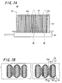
- Figs. 7A and 7B each show a schematic diagram of one example of such a fuel cell stack.
- Fig. 7A is a side view schematically showing a conventional fuel cell stack 51
- Fig. 7B is a partly enlarged plan view of the conventional fuel cell stack 51.
- the left-hand part shows an enlarged plan view of Section VII of Fig. 7A
- the right-hand part shows an enlarged plan view of Section VIII of Fig. 7A
- a plurality of fuel cells are arranged side by side in such a manner as to provide uniformity in the interval between the adjacent fuel cells.
- the fuel cells constituting the fuel cell stack produce heat in accompaniment with generation of electric power.
- the heat produced with the electric power generation in the fuel cells is dissipated through a gap between the adjacent fuel cells and so forth.
- the fuel cells liberate heat energy due to Joule heat and reaction heat of their own in the course of electric power generation.
- the heat energy cannot be dissipated readily and thus the temperature tends to become higher.
- the midportion of the fuel cell stack in the direction of arrangement of the fuel cells is high in temperature, whereas the end part of the fuel cell stack in the direction of arrangement of the fuel cells is low in temperature. Therefore, the fuel cell stack poses nonuniformity of temperature distribution (hill-form temperature distribution) in the direction of arrangement of the fuel cells, which may cause a decrease in power generation efficiency.
- JP 06251790 A discloses a fuel cell where plural unit cells and separator plates are laminated alternately. A thickness of the separator plate in the central part of the stack is made thicker than in the other part.
- EP 1686642 A1 discloses a fuel cell stack in which electricity generators and separators are stacked.
- the stack comprises heat releasing means. Those in the center of the stack are thicker than other ones.
- the invention provides a fuel cell stack comprising:
- the interval between adjacent fuel cells arranged in the midportion of the fuel cell stack in the direction of arrangement of the fuel cells (hereafter occasionally abbreviated as “midportion") is set to be wider than the interval between adjacent fuel cells arranged at either end of the fuel cell stack in the direction of arrangement of the fuel cells (hereafter occasionally abbreviated as "end”).
- the fuel cells in the middle of the stack are thinner than those at the ends of the stade. By doing so, the temperature distribution in the direction of placement of the fuel cell stack can be made uniform (or made as nearly uniform as possible).
- the fuel cells liberate heat energy due to Joule heat and reaction heat of their own in the course of electric power generation.
- the heat energy cannot be dissipated readily and thus the temperature becomes higher.
- the temperature distribution becomes uneven; that is, the midportion of the fuel cell stack is in a high-temperature state, whereas either end of the fuel cell stack is in a low-temperature state. This may cause a decrease in power generating efficiency.
- the interval between a plurality of the fuel cells arranged in the midportion of the fuel cell stack in the direction of arrangement of the fuel cells is set to be wider than the interval between a plurality of the fuel cells arranged at either end of the fuel cell stack in the direction of arrangement of the fuel cells. This helps facilitate heat-energy dissipation in a plurality of the fuel cells arranged in the midportion, wherefore the temperature of a plurality of the fuel cells arranged in the midportion can be lowered.
- the interval between the adjacent fuel cells is set to be narrower than the interval between the adjacent ones of a plurality of the fuel cells arranged in the midportion.
- the plurality of the fuel cells arranged at either end are so arranged that the interval between the adjacent fuel cells becomes narrower gradually with approach toward a corresponding extremity in the direction of arrangement of the fuel cells.
- the plurality of the fuel cells arranged at either end are so arranged that the interval between the adjacent fuel cells becomes narrower gradually from the midportion to the corresponding extremity in the direction of arrangement of the fuel cells.
- the interval between the adjacent fuel cells varies, for example, increases (or decreases) rapidly, it is possible to suppress application of an excessive stress to a plurality of the fuel cells arranged at either end, and thereby enhance the reliability of the fuel cell stack.
- the plurality of the fuel cells arranged in the midportion in the direction of arrangement of the fuel cells are made smaller in thickness than the plurality of the fuel cells arranged at either end in the direction of arrangement of the fuel cells.
- the interval between the center of one fuel cell and the center of the other fuel cell (for example, the interval between the fuel gas paths, respectively, of the adjacent fuel cells) is set at a fixed value, and the fuel cells arranged in the midportion in the direction of arrangement of the fuel cells are made smaller in thickness than the fuel cells arranged at either end in the arrangement direction.
- the interval between a plurality of the fuel cells arranged in the midportion is wider than the interval between a plurality of the fuel cells arranged at either end, wherefore the temperature distribution in the direction of placement of the fuel cell stack can be made uniform (or made as nearly uniform as possible).
- the fuel cell is a hollow flat plate-shaped fuel cell and is disposed uprightly in a manifold for supplying a fuel gas to the fuel cell.
- the fuel cell is formed in the shape of a hollow flat plate and is disposed uprightly in the manifold for supplying a fuel gas to the fuel cell.
- the fuel cell stack in which are arranged the fuel cells side by side at varying intervals, as well as to supply a fuel gas to the fuel cells.
- the fuel cell in the shape of a hollow flat plate, it is possible to manufacture with ease the fuel cell stack that is low in electrical resistance and is thus capable of exhibiting high power generation capability, in which are arranged the fuel cells side by side at varying intervals.
- the invention provides a fuel cell apparatus comprising:
- the fuel cell stack inside the housing are accommodated the fuel cell stack and the oxygen-containing gas supply means for feeding an oxygen-containing gas to the fuel cell.
- an oxygen-containing gas is supplied from the side face of the fuel cell stack along the direction of arrangement of the fuel cells, and the thereby supplied oxygen-containing gas flows between the fuel cells.
- the oxygen-containing gas traveling between the fuel cells it is possible to decrease the temperature of the fuel cells.
- a wider interval is secured between a plurality of the fuel cells arranged in the midportion in the direction of arrangement of the fuel cells. This makes it possible to increase the amount of flow of the oxygen-containing gas flowing between a plurality of the fuel cells arranged in the midportion, and thereby enhance the effect of cooling down a plurality of the fuel cells arranged in the midportion.
- the interval between the adjacent ones is set to be narrower than the interval between a plurality of the fuel cells arranged in the midportion. Therefore, the amount of flow of the oxygen-containing gas flowing between a plurality of the fuel cells arranged at either end is smaller than the amount of flow of the oxygen-containing gas flowing between a plurality of the fuel cells arranged in the midportion. As a result, the cooling effect exerted on a plurality of the fuel cells arranged at either end is lower than the cooling effect exerted on a plurality of the fuel cells arranged in the midportion.
- the temperature distribution of the fuel cell stack can be made uniform (or made as nearly uniform as possible) even further and a decrease in power generation efficiency in the fuel cell stack can be suppressed. Accordingly, it is possible to obtain a fuel cell apparatus that succeeds in providing enhanced power generation efficiency.
- the fuel cells are electrically connected in series to each other via a power collecting member, and that the power collecting member is so shaped as to permit of circulation of the oxygen-containing gas.
- the power collecting member is so shaped as to permit of circulation of the oxygen-containing gas. This makes it possible to allow the oxygen-containing gas supplied from the side face of the fuel cell stack along the direction of arrangement of the fuel cells to flow between the adjacent fuel cells readily. In this way, the temperature distribution of the fuel cell stack can be uniformized (or made as nearly uniform as possible), wherefore it is possible to produce a fuel cell apparatus that succeeds in providing enhanced power generation efficiency.
- the oxygen-containing gas supply means is disposed so that the oxygen-containing gas is allowed to flow within the oxygen-containing gas supply means in a direction from top to bottom along the fuel cell.
- the oxygen-containing gas supply means is disposed so that the oxygen-containing gas is allowed to flow within the oxygen-containing gas supply means in the direction from top to bottom along the fuel cell. In this way, the temperature distribution in the direction of from top to bottom of the fuel cell can be uniformized (or made as nearly uniform as possible).
- the fuel cells constituting the fuel cell stack show a tendency that the upper part thereof is in a high-temperature state, whereas the lower part thereof is in a low-temperature state.
- the oxygen-containing gas is allowed to flow within the oxygen-containing gas supply means in the direction from top to bottom along the fuel cell, the oxygen-containing gas is heated up while flowing through the fuel cell in the direction from top to bottom thereof.
- the oxygen-containing gas in a heated state flows toward the lower part of the fuel cell, wherefore the temperature of the lower part of the fuel cell can be raised.
- the temperature distribution in the direction of from top to bottom of the fuel cell can be uniformized. This makes it possible to enhance the power generation efficiency in the fuel cell, and thereby produce a fuel cell apparatus that succeeds in providing enhanced power generation efficiency.
- a reformer for generating a fuel gas which is supplied to the fuel cell is provided above the fuel cell stack.
- the reformer for generating a fuel gas which is supplied to the fuel cell is provided above the fuel cell stack.
- the reformer is heated up by the heat from the fuel cell stack.
- the temperature distribution in the direction of arrangement of the fuel cells can be uniformized (or made as nearly uniform as possible). Therefore, the temperature of the reformer can be raised more efficiently and a reforming reaction can thus be developed efficiently in the reformer. This makes it possible to produce a fuel cell apparatus whose power generation efficiency is enhanced even further.
- the interval between a plurality of the fuel cells arranged in the midportion in the direction of arrangement of the fuel cells is set to be wider than the interval between a plurality of the fuel cells arranged at either end in the direction of arrangement of the fuel cells. In this way, the temperature distribution of the fuel cell stack in the direction of arrangement of the fuel cells can be uniformized, wherefore a decrease in power generation efficiency can be suppressed.
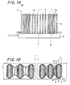
- Figs. 1A and 1B show a fuel cell stack apparatus 10 having a fuel cell stack 1.
- Fig. 1A is a side view schematically showing the fuel cell stack apparatus 10
- Fig. 1B is a partly enlarged plan view of the fuel cell stack apparatus 10 depicted in Fig. 1A .
- the left-hand part shows an enlarged plan view of Section I of Fig. 1A
- the right-hand part shows an enlarged plan view of Section II of Fig. 1A .
- like members are identified by the same reference numbers, and this holds true for what follows.
- an arrow shown by a dotted line in Fig. 1B indicates a direction in which an oxygen-containing gas flows.
- the fuel cell stack apparatus 10 of the invention includes the fuel cell stack 1 and a manifold 12.
- the fuel cell stack 1 is constructed by electrically connecting a plurality of fuel cells 2 in series with each other.
- Each of the fuel cells 2 is formed by laminating a fuel-side electrode layer 5, a solid-state electrolytic layer 6, and an air-side electrode layer 4 one after another on a support substrate 8.
- the fuel cell stack 1 is fixedly attached to the manifold 12, with the fuel cells 2 arranged in an array.
- a power collecting member 3a is set between the adjacent fuel cells 2
- an end-side power collecting member 3b is set between the adjacent fuel cells 2 located on either side of the fuel cell stack in the direction of arrangement of the fuel cells 2.
- the fuel cell stack apparatus 10 is provided with an alloy-made holding member 13 which is uprightly fixed to the manifold 12 for supplying a fuel gas to the fuel cells 2 so as to retain the fuel cell stack 1 via the end-side power collecting member 3b from either side of the fuel cell stack in the direction of arrangement of the fuel cells 2.
- one ends (lower ends) of, respectively, the fuel cell 2 and the holding member 13 are buried in and bonded to the manifold 12 by means of, for example, a glass sealing material (not shown in the figure) having high heat resistance.
- the fuel cell 2 is formed in the shape of a hollow flat plate.
- the fuel cell 2 is constructed of a columnar conductive support substrate 8 having a pair of opposite flat surfaces, on one of the flat surfaces of which are successively laminated the fuel-side electrode layer 5, the solid-state electrolytic layer 6, and the air-side electrode layer 4, and on the other flat surface of which is disposed an interconnector 7.
- a fuel gas flow channel 9 is disposed in the conductive support substrate 8 interiorly thereof for permitting of circulation of a reaction gas (fuel gas).
- a reaction gas fuel gas
- such a configuration is defined as "hollow flat-plate shape”.
- a P-type semiconductor 11 may be disposed on the outer surface (top surface) of the interconnector 7.
- the P-type semiconductor 11 By connecting the power collecting member 3a to the interconnector 7 via the P-type semiconductor 11, it is possible to establish ohmic contact between them. In this case, the degree of potential drop is lessened, wherefore a deterioration in electricity collecting capability can be avoided effectively. Note that each of the components constituting the fuel cell 2 will hereafter be described in detail.
- the conductive support substrate 8 may be so designed as to serve also as the fuel-side electrode layer 5.
- the fuel cell 2 can be constructed by laminating, on the surface of such a conductive support substrate, the solid-state electrolytic layer 6 and the air-side electrode layer 4 successively.
- the fuel cell stack 1 is characterized in that the interval between a plurality of the fuel cells 2 arranged in the midportion of the fuel cell stack in the direction of arrangement of the fuel cells 2 is set to be wider than the interval between a plurality of the fuel cells 2 arranged at either end of the fuel cell stack in the direction of arrangement of the fuel cells 2.
- a plurality of the fuel cells 2 arranged in the midportion of the fuel cell stack in the direction of arrangement of the fuel cells 2 refer to the fuel cells arranged centrally in the direction of arrangement of a plurality of the fuel cells 2 and the fuel cells arranged in the vicinity thereof.
- the number of the fuel cells concerned may be determined as appropriate.
- the number of the fuel cells concerned may also be determined as appropriate in consideration of the length of the fuel cell stack in the direction of arrangement of the fuel cells 2, the size of the fuel cell 2, and so forth.
- the fuel cells 2 arranged within a region constituting about a third of the length of the fuel cell stack located centrally with respect to the midportion in the direction of arrangement of the fuel cells 2 can be defined as "a plurality of the fuel cells 2 arranged in the midportion”
- the fuel cells 2 arranged within a region constituting about a third of the length of the fuel cell stack lying between either end and the midportion in the direction of arrangement of the fuel cells 2 can be defined as "a plurality of the fuel cells 2 arranged at either end”.
- a group of a plurality of the fuel cells 2 arranged in the midportion and a group of a plurality of the fuel cells 2 arranged at either end can be arranged the fuel cell 2 which is independent of the two groups.
- the fuel cell stack constructed by arranging a plurality of the fuel cells produces heat in accompaniment with generation of electric power in the fuel cells.
- the fuel cell stack constructed by arranging a plurality of the fuel cells incurs uneven temperature distribution in the direction of arrangement of the fuel cells (the midportion is in a high-temperature state, whereas either end is in a low-temperature state). This may cause a deterioration in the power generation capability of the fuel cell stack.
- the interval between a plurality of the fuel cells 2 arranged in the midportion of the fuel cell stack in the direction of arrangement of the fuel cells 2 is set to be wider than the interval between a plurality of the fuel cells 2 arranged at either end of the fuel cell stack in the direction of arrangement of the fuel cells 2. This helps facilitate heat-energy dissipation in the fuel cells 2 arranged in the midportion, wherefore the temperature of the midportion of the fuel cell stack 1 can be lowered.
- the interval between the adjacent fuel cells 2 is set to be narrower than the interval between a plurality of the fuel cells 2 arranged in the midportion. Therefore, as compared with the case for the midportion, the heat energy cannot be dissipated readily, with the result that a drop in the temperature of the end-side part of the fuel cell stack 1 is suppressed or the temperature of the end-side part is caused to rise.
- the fuel cell stack 1 assumes a gently-curved temperature distribution shape. Moreover, by making adjustment to the interval between the adjacent fuel cells 2 properly, it is possible to make the temperature distribution of the fuel cell stack 1 as nearly uniform as possible.
- the fuel cell stack 1 of the invention can be implemented as the fuel cell stack 1 that offers improved power generation capability.
- the interval between a plurality of the fuel cells 2 arranged at either end be narrower than the interval between a plurality of the fuel cells 2 arranged in the midportion. That is, in a plurality of the fuel cells 2 arranged in the midportion or at either end, the adjacent fuel cells 2 may be arranged at a uniform interval. Further, a plurality of the fuel cells 2 arranged at either end may be so arranged that the interval between the adjacent fuel cells 2 becomes wider gradually with approach toward the corresponding extremity.
- the support substrate 8 is required to be gas-permeable for allowing a fuel gas to permeate to the fuel-side electrode layer 5, and is also required to be electrically conductive for collecting electricity through the interconnector 7. It is thus necessary to adopt a material that satisfies such requirements for the support substrate 8. For example, electrically conductive ceramic or cermet may be used.
- the power collecting member 3a and the end-side power collecting member 3b may be constructed of a component made of an elastic metal or alloy, or a component formed by performing a predetermined surface treatment on a felt made of metallic fiber or alloy fiber.
- the power collecting member 3a of the invention should preferably be constructed of a component made of an elastic alloy. This makes it possible to establish electrical connection of the fuel cells 2. Note that, for example, it is possible to place the power collecting member 3a whose size is changed in accordance with the interval between the fuel cells 2. The shape of the power collecting member 3a will be described later on.
- the air-side electrode layer 4 may be formed of electrically conductive ceramic made of a so-called ABO 3 type perovskite oxide.
- the air-side electrode layer 4 needs to be designed to exhibit gas permeability and should preferably have an open porosity of greater than or equal to 20%, and more particularly an open porosity falling within a range from 30 to 50%.
- the fuel-side electrode layer 5 may be formed of porous conductive ceramic, for example, ZrO 2 solid solution containing a rare earth element (called stabilized zirconia), and Ni and/or NiO.
- porous conductive ceramic for example, ZrO 2 solid solution containing a rare earth element (called stabilized zirconia), and Ni and/or NiO.
- the solid-state electrolytic layer 6 is required to function as an electrolyte for interfacing electrons between the electrodes, as well as to have a gas barrier property for prevention of the leakage of a fuel gas and an oxygen-containing gas.
- the solid-state electrolytic layer 6 is thus formed of ZrO 2 solid solution containing a rare earth element in an amount of 3 to 15 mol%. Note that any other material may be used to form the solid-state electrolytic layer 6 so long as it has the aforestated characteristics.
- the interconnector 7 which may be formed of electrically conductive ceramic, is required to exhibit resistance to reduction and resistance to oxidation as well because it is brought into contact with a fuel gas (hydrogen gas) and an oxygen-containing gas (air or the like). Therefore, a lanthanum chromite-based perovskite-type oxide (LaCrO 3 -based oxide) is desirable for use.
- the interconnector 7 In order to prevent the leakage of a fuel gas which passes through the fuel gas flow channel 9 formed in the support substrate 8 and the leakage of an oxygen-containing gas which flows outside of the support substrate 8 as well, the interconnector 7 needs to have a dense. It is thus preferable that the interconnector 7 has a relative density of 93% or above, and more particularly 95% or above.
- the support substrate 8 may be designed as a hollow flat plate-shaped support substrate.
- the support substrate 8 is formed in the shape of a slim plate-like piece that extends in an upstanding direction and has opposite flat surfaces and opposite semicircular side faces.
- a plurality (six pieces, in Fig. 1B ) of fuel gas flow channels 9 so as to pass through the interior of the support substrate 8 in the upstanding direction.
- Each of the fuel cells 2 is bonded to the upper wall (top) of the manifold 12 for supplying a fuel gas by means of, for example, a glass sealing material 12 having high heat resistance.
- the fuel gas flow channel 9 of the fuel cell 2 is communicated with a fuel gas chamber (not shown in the figure).
- the support substrate 8 is produced by co-firing with at least one of the fuel-side electrode layer 5 and the solid-state electrolytic layer 6, it is desirable to form the support substrate 8 with use of an iron-family metal component and a specific rare earth oxide.
- the conductive support substrate 8 should preferably have an open porosity of greater than or equal to 30%, and more particularly an open porosity falling within a range from 35 to 50%. It is also preferable that the electrical conductivity of the conductive support substrate 8 is greater than or equal to 300S/cm, and more particularly greater than or equal to 440S/cm.
- a layer made of a transition metal perovskite-type oxide may be taken up.
- P-type semiconductor layer 6 ranges in thickness from 30 to 100 ⁇ m.
- the fuel cell 2 constituting the fuel cell stack 1 is illustrated as a hollow flat plate-shaped fuel cell, and the fuel cell stack 1 is illustrated as being composed of the fuel cells 2 of the same thickness (having the same thickness in the arrangement direction).
- the fuel cell stack 1 is illustrated as being composed of the fuel cells 2 of the same thickness (having the same thickness in the arrangement direction).
- the fuel cells 2 may vary in thickness (have different thicknesses in the arrangement direction).
- the interval between the adjacent fuel cells arranged in the midportion may be determined as appropriate in consideration of the shape of the fuel cell, the number of the fuel cells, and so forth.
- the interval between the adjacent fuel cells arranged in the midportion may be set at 3 mm, and the interval between the adjacent fuel cells arranged at either end may be set at 2 mm.
- the interval between the fuel cells may be defined as "the interval between the surfaces of the adjacent fuel cells”.
- Figs. 2A and 2B show an example of a fuel cell stack apparatus 14 in which a plurality of the fuel cells 2 arranged at either end are so arranged that the interval between the adjacent fuel cells 2 becomes narrower gradually with approach toward the corresponding extremity in the direction of arrangement of the fuel cells 2.
- Fig. 2A is a side view schematically showing the fuel cell stack apparatus 14
- Fig. 2B is a partly enlarged plan view of the fuel cell stack apparatus 14 depicted in Fig. 2A .
- the left-hand part shows an enlarged plan view of Section III of Fig. 2A
- the right-hand part shows an enlarged plan view of Section IV of Fig. 2A .
- a fuel cell stack 15 thereby constructed, a plurality of the fuel cells 2 arranged at either end are so arranged that the interval between the adjacent fuel cells 2 becomes narrower gradually from the midportion to the corresponding extremity in the direction of arrangement of the fuel cells 2.
- the temperature distribution of the fuel cell stack 15 can be made as nearly uniform as possible.
- a plurality of the fuel cells 2 arranged at either end are so arranged that the interval between the adjacent fuel cells 2 becomes narrower gradually with approach toward the corresponding extremity in the arrangement direction.
- the interval between the adjacent fuel cells 2 varies, for example, increases (or decreases) suddenly, it is possible to suppress application of an excessive stress to the fuel cells 2 and the power collecting member 3a, and thereby enhance the reliability of the fuel cell stack 14.
- the fuel cells 2 may be so arranged that the interval between the adjacent fuel cells 2 becomes narrower gradually from the midportion to either end in the direction of arrangement of the fuel cells 2.
- Fig. 2 there is shown such a fuel cell stack apparatus 14 in which the temperature distribution of the fuel cell stack 15 can be made as nearly uniform as possible even further.
- Figs. 3A and 3B show an example of a fuel cell stack apparatus 16 in which a plurality of the fuel cells 2 arranged in the midportion are made smaller in thickness (thickness in the arrangement direction) than a plurality of the fuel cells 2 arranged at either end.
- Fig. 3A is a side view schematically showing the fuel cell stack apparatus 16
- Fig. 3B is a partly enlarged plan view of the fuel cell stack apparatus 16 depicted in Fig. 3A .
- the left-hand part shows an enlarged plan view of Section V of Fig. 3A
- the right-hand part shows an enlarged plan view of Section VI of Fig. 3A .
- the interval between the adjacent fuel cells (for example, the interval between the center of one fuel cell and the center of the other fuel cell in a plan view thereof) is set at a predetermined value, and a plurality of the fuel cells 2 arranged in the midportion are made smaller in thickness than a plurality of the fuel cells 2 arranged at either end. In this way, the interval between the adjacent ones of a plurality of the fuel cells 2 arranged in the midportion is wider than the interval between the adjacent ones of a plurality of the fuel cells 2 arranged at either end.
- the interval between the adjacent fuel cells 2 (the interval between the center of one fuel cell 2 and the center of the fuel cell 2 placed adjacent thereto) is set at 5 mm. Then, the thickness of each of a plurality of the fuel cells 2 arranged in the midportion is set at 2 mm and the thickness of each of a plurality of the fuel cells 2 arranged at either end is set at 3 mm. In this way, the interval between a plurality of the fuel cells 2 arranged in the midportion is wider than the interval between a plurality of the fuel cells 2 arranged at either end.
- the interval between the adjacent fuel cells 2 and the thickness of the fuel cell 2 may be determined as appropriate in consideration of the size of the fuel cell, the size of the fuel cell stack, and so forth. For example, in a plurality of the fuel cells arranged at either end, the thickness of the fuel cell 2 may be charged on an as needed basis so long as it is smaller than the thickness of each of a plurality of the fuel cells 2 arranged in the midportion.
- the fuel cell apparatus of the invention can be provided.
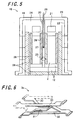
- Fig. 4 is an external perspective view showing one example of a fuel cell apparatus according to the invention.
- a fuel cell apparatus 18 is constructed by placing, inside a housing 19 having the shape of a rectangular prism, the aforestated fuel cell stack and oxygen-containing gas supply means 20 for feeding an oxygen-containing gas to the fuel cell 2.
- the fuel cell stack for use the fuel cell stack 1 shown in Figs. 1A and 1B is exemplified.
- a reformer 21 for generating a hydrogen gas by reforming a fuel such as a natural gas and kerosene.
- a fuel such as a natural gas and kerosene.
- Fig. 4 there is shown a state where part of the housing 19 (front face and rear face) has been removed and the fuel cell stack apparatus 10 placed inside the housing 19 has been pulled out backward.
- the fuel cell stack apparatus 10 can be slidingly accommodated inside the housing 19.
- Fig. 5 is a sectional view of the fuel cell apparatus 18 taken along the section line X-X shown in Fig. 4 .
- the housing 19 constituting the fuel 18 takes on a dual structure having an inner wall 22 and an outer wall 23.
- the outer wall 23 constitutes the outer frame of the housing 19, whereas the inner wall 22 constitutes a power generating chamber 24 for housing the fuel cell stack 1 (the fuel cell stack apparatus 10).
- a region between the inner wall 22 and the outer wall 23 serves as a flow channel for a reaction gas which is introduced into the fuel cell 2.
- a reaction gas which is introduced into the fuel cell 2.
- an oxygen-containing gas and so forth to be introduced into the fuel cell 2 flow through the flow channel.
- an oxygen-containing gas introducing member 20 acting as the oxygen-containing gas supply means which extends from the top surface of the inner wall 22 to the side-face part of the fuel cell stack 1, is adapted to the width of the fuel cell stack 1 in the arrangement direction, and communicates with the flow channel constituted by the inner wall 22 and the outer wall 23, for introducing an oxygen-containing gas into the fuel cell 2.
- an outlet port 25 for introducing an oxygen-containing gas into the fuel cell 2.
- the oxygen-containing gas introducing member 20 is so designed that a pair of plate-like members arranged side by side at a predetermined spacing constitutes an oxygen-containing gas introducing flow channel and that its lower end is bonded to a bottom member. Moreover, while, in Fig. 5 , the oxygen-containing gas introducing member 20 is so placed as to be located between the two fuel cell stacks 1 (fuel cell stack apparatuses 10) juxtaposed to each other within the housing 19, depending upon the number of the fuel cell stacks 1 to be housed, for example, the oxygen-containing gas introducing member 20 may be so disposed as to sandwich the fuel cell stacks 1 from their side faces.
- a temperature sensor 26 having a temperature measuring portion 27 is inserted into the oxygen-containing gas introducing member 20 from the top-surface side of the housing 2. This makes it possible to measure the temperature of the fuel cell stack 1 (the fuel cell 2).
- a suitable heat insulating material 28 is placed inside the housing 19 . Note that a plurality of the temperature sensors 26 may be arranged for use. In this case, they should preferably be arranged in the midportion and the end-side part of the fuel cell stack, respectively.
- a fuel gas is supplied from the manifold 12 to the fuel cell 2 and an oxygen-containing gas is supplied to the fuel cell 2 as well. With use of these gases, electric power is generated.
- the supply of an oxygen-containing gas is effected by the oxygen-containing gas introducing member 20 to the fuel cell stack 1 through its side face along the direction of arrangement of the fuel cells 2, and the oxygen-containing gas flows between the fuel cells 2.
- an oxygen-containing gas is supplied in such a manner that it is introduced from a certain location in the direction of the side face of the fuel cells 2 (the fuel cell stack 1) and goes around the fuel cell stack 1 as a whole.
- a wider interval is secured between a plurality of the fuel cells 2 arranged in the midportion in the direction of arrangement of the fuel cells 2. This makes it possible to increase the amount of flow of the oxygen-containing gas flowing between a plurality of the fuel cells 2 arranged in the midportion, and thereby enhance the effect of cooling down a plurality of the fuel cells 2 arranged in the midportion (the effect of heat exchange).
- the interval of the adjacent fuel cells 2 is set to be narrower. Therefore, the amount of flow of the oxygen-containing gas flowing between a plurality of the fuel cells 2 arranged at either end is smaller than the amount of flow of the oxygen-containing gas flowing between a plurality of the fuel cells 2 arranged in the midportion. As a result, the cooling effect exerted on the fuel cells 2 arranged at either end is lower than that exerted on the fuel cells 2 arranged in the midportion.
- the temperature of a plurality of the fuel cells 2 arranged in the midportion in the direction of arrangement of the fuel cells 2 becomes even lower. This makes it possible to render the temperature distribution of the fuel cell stack 1 as nearly uniform as possible, and thereby suppress a decrease in power generation efficiency in the fuel cell stack 1.
- the oxygen-containing gas introducing member 20 shown in Fig. 5 is placed in such a manner that an oxygen-containing gas is allowed to flow within the oxygen-containing gas introducing member 20 in the direction from top to bottom along the fuel cell 2.
- the reformer 21 for supplying a fuel gas (reformed gas) to the fuel cell 2 (the manifold 12) is placed above the fuel cell stack 1.
- the fuel cells 2 constituting the fuel cell stack 1 show a tendency that the upper part thereof is in a high-temperature state, whereas the lower part thereof is in a low-temperature state.
- the oxygen-containing gas is allowed to flow within the oxygen-containing gas supply means 20 in the direction from top to bottom along the fuel cell 2, the oxygen-containing gas is heated up while flowing through the fuel cell 2 in the direction from top to bottom thereof.
- the oxygen-containing gas in a heated state is supplied, through the outlet port 25 formed on the lower-end side of the oxygen-containing gas introducing member 20, to the lower part of the fuel cell 20.
- the temperature of the lower part of the fuel cell 20 can be raised.
- the temperature distribution in the direction of from top to bottom (upstanding direction) of the fuel cell 20 can be uniformized, wherefore the power generation efficiency in the fuel cell 20 can be enhanced.
- the heat from the fuel cell stack 1 is transmitted to the reformer 21, whereupon the bottom surface of the reformer 21 is heated up.
- the reformer 21 is able to enhance a reforming reaction by exploiting the heat from the fuel cell stack 1 effectively.
- the temperature distribution in the direction of arrangement of the fuel cells 2 can be made as nearly uniform as possible, it follows that the reformer 21 can be heated, with its temperature kept more even. Accordingly, a reforming reaction in the reformer 21 can be conducted efficiently, wherefore the fuel cell apparatus 18 succeeds in providing enhanced power generation efficiency.
- Fig. 6 shows one example of the power collecting member 3a disposed between the adjacent fuel cells 2 in the fuel cell stack 1.
- the power collecting member 3a has, as basic elements, a first electrical conductor piece 30 which abuts against the flat surface of one of the adjacent fuel cells 2, a second electrical conductor piece 31 which extends inclinedly from the end of one of the adjacent fuel cells 2 to the end of the other of the adjacent fuel cells 2, a third electrical conductor piece 32 which abuts against the flat surface of the other of the adjacent fuel cells 2, and a fourth electrical conductor piece 33 which extends inclinedly from the end of the other of the adjacent fuel cells 2 to the end of one of the adjacent fuel cells 2.
- the first to fourth electrical conductor pieces are each connected to respective following electrical conductor pieces at their ends in this order, and further, the electrical conductor pieces are repeatedly connected in this order. These connections constitute a unitary power collecting member 3a extending in an axial direction thereof.
- the end-side power collecting member 3b may be similar in configuration to the power collecting member 3a.
- the temperature distribution of the fuel cell stack 1 can be made as nearly uniform as possible, it is possible to suppress a decrease in power generation efficiency in the fuel cell stack 1. That is, there is obtained a fuel cell apparatus that succeeds in providing enhanced power generation efficiency.
- the description of the fuel cell stack of the invention deals with the case of using a hollow flat plate-shaped fuel cell as the fuel cell
- a plate-shaped or cylindrical-shaped fuel cell may be used instead.
- the interval between the fuel cells may be varied by making changes to the sizes of, respectively, the oxygen-side electrode layer, the fuel-side electrode layer, the separator, and so forth that constitute the fuel cell.
Landscapes
- Life Sciences & Earth Sciences (AREA)
- Engineering & Computer Science (AREA)
- Manufacturing & Machinery (AREA)
- Sustainable Development (AREA)
- Sustainable Energy (AREA)
- Chemical & Material Sciences (AREA)
- Chemical Kinetics & Catalysis (AREA)
- Electrochemistry (AREA)
- General Chemical & Material Sciences (AREA)
- Fuel Cell (AREA)
Claims (7)
- Assemblage de piles à combustible comprenant :un ensemble d'une pluralité de piles à combustible (2) électriquement connectées en série les unes aux autres, les piles à combustible (2) étant chacune formées par stratification d'une couche (5) d'électrode de côté combustible, d'une couche (6) électrolytique à l'état solide, et d'une couche (4) d'électrode de côté air l'une après l'autre sur un substrat support (8), un intervalle entre piles à combustible (2) adjacentes agencées dans une partie médiane de l'assemblage (1, 15, 17) de piles à combustible dans un sens d'agencement des piles à combustible (2) étant plus large qu'un intervalle entre piles à combustible (2) adjacentes agencées à l'une ou l'autre extrémité de l'assemblage (1, 15, 17) de piles à combustible dans le sens d'agencement des piles à combustible,caractérisé en ce quela pluralité des piles à combustible (2) agencées dans la partie médiane dans le sens d'agencement des piles à combustible (2) sont réalisées plus petites en épaisseur que la pluralité des piles à combustible (2) agencées à l'une ou l'autre extrémité dans le sens d'agencement des piles à combustible (2).
- Assemblage de piles à combustible selon la revendication 1, dans lequel la pluralité des piles à combustible (2) agencées à l'une ou l'autre extrémité sont agencées de telle manière que l'intervalle entre les piles à combustible (2) adjacentes devient graduellement plus étroit en approchant vers une extrémité correspondante dans le sens d'agencement des piles à combustible (2).
- Assemblage de piles à combustible selon la revendication 1 ou 2, dans lequel la pile à combustible (2) est une pile à combustible creuse en forme de plaque plate et est disposée verticalement dans un collecteur pour délivrer un gaz combustible à la pile à combustible (2).
- Appareil à piles à combustible comprenant :l'assemblage (1, 15, 17) de piles à combustible selon l'une quelconque des revendications 1 à 3 ;un moyen (20) d'alimentation en gaz contenant de l'oxygène pour alimenter un gaz contenant de l'oxygène dans la pile à combustible (2) ; etun logement (19) pour recevoir dans celui-ci l'assemblage (1, 15, 17) de piles à combustible et le moyen (20) d'alimentation en gaz contenant de l'oxygène,un gaz contenant de l'oxygène étant alimenté depuis une face latérale de l'assemblage (1, 15, 17) de piles à combustible dans le sens d'agencement des piles à combustible (2), et le gaz contenant de l'oxygène s'écoulant entre les piles à combustible (2).
- Appareil à piles à combustible selon la revendication 4, dans lequel les piles à combustible (2) sont électriquement connectées en série les unes aux autres par l'intermédiaire d'un élément (3a) de collecte d'énergie, et l'élément de collecte d'énergie est formé de façon à permettre la circulation du gaz contenant de l'oxygène.
- Appareil à piles à combustible selon la revendication 4 ou 5, dans lequel le moyen (20) d'alimentation en gaz contenant de l'oxygène est disposé de telle façon que le gaz contenant de l'oxygène est laissé s'écouler à l'intérieur du moyen (20) d'alimentation en gaz contenant de l'oxygène dans un sens du haut vers le bas le long de la pile à combustible (2).
- Appareil à piles à combustible selon l'une quelconque des revendications 4 à 6, dans lequel un reformeur (21) pour générer un gaz combustible qui est alimenté jusqu'à la pile à combustible (2) est prévu au sommet de l'assemblage (1, 15, 17) de piles à combustible monté.
Applications Claiming Priority (2)
| Application Number | Priority Date | Filing Date | Title |
|---|---|---|---|
| JP2006262418 | 2006-09-27 | ||
| PCT/JP2007/068721 WO2008041593A1 (fr) | 2006-09-27 | 2007-09-26 | Empilement de cellules de pile à combustible et pile à combustible |
Publications (3)
| Publication Number | Publication Date |
|---|---|
| EP2077597A1 EP2077597A1 (fr) | 2009-07-08 |
| EP2077597A4 EP2077597A4 (fr) | 2010-11-10 |
| EP2077597B1 true EP2077597B1 (fr) | 2014-11-19 |
Family
ID=39268455
Family Applications (1)
| Application Number | Title | Priority Date | Filing Date |
|---|---|---|---|
| EP07828467.6A Ceased EP2077597B1 (fr) | 2006-09-27 | 2007-09-26 | Empilement de piles à combustible ayant une distribution de température homgène le long de l'axe d'empilement |
Country Status (5)
| Country | Link |
|---|---|
| US (1) | US20090239121A1 (fr) |
| EP (1) | EP2077597B1 (fr) |
| CN (1) | CN101517805A (fr) |
| CA (1) | CA2664367A1 (fr) |
| WO (1) | WO2008041593A1 (fr) |
Families Citing this family (17)
| Publication number | Priority date | Publication date | Assignee | Title |
|---|---|---|---|---|
| WO2009016857A1 (fr) * | 2007-07-27 | 2009-02-05 | Kyocera Corporation | Module de pile à combustible et dispositif de pile à combustible ayant le module |
| JP5164630B2 (ja) * | 2008-03-25 | 2013-03-21 | 京セラ株式会社 | セルスタックおよび燃料電池モジュール |
| JP2010080266A (ja) * | 2008-09-26 | 2010-04-08 | Kyocera Corp | 燃料電池セルスタック装置およびそれを具備する燃料電池モジュールならびに燃料電池装置 |
| JP5119234B2 (ja) | 2009-12-21 | 2013-01-16 | トヨタ自動車株式会社 | 燃料電池モジュール |
| CA2853969C (fr) * | 2011-11-02 | 2016-10-04 | Ngk Spark Plug Co., Ltd. | Pile a combustible avec echangeur de chaleur integre |
| WO2014123150A1 (fr) * | 2013-02-07 | 2014-08-14 | 日本特殊陶業株式会社 | Pile à combustible et procédé de fabrication associé |
| EP2988354B1 (fr) | 2013-04-16 | 2016-10-05 | Panasonic Intellectual Property Management Co., Ltd. | Système de piles à combustible |
| EP3035431B1 (fr) * | 2014-12-19 | 2019-04-24 | Hexis AG | Module de piles a combustible et procede de fonctionnement d'un module de piles a combustible |
| WO2017038893A1 (fr) * | 2015-08-31 | 2017-03-09 | 京セラ株式会社 | Module de piles à combustible et dispositif de piles à combustible |
| CN109314260B (zh) * | 2016-06-20 | 2022-03-11 | 京瓷株式会社 | 燃料电池模块、燃料电池装置以及燃料电池模块的制造方法 |
| JP6368762B2 (ja) * | 2016-11-29 | 2018-08-01 | 日本碍子株式会社 | 燃料電池スタック |
| JP6368761B2 (ja) * | 2016-11-29 | 2018-08-01 | 日本碍子株式会社 | 燃料電池スタック |
| US10388979B2 (en) * | 2017-05-04 | 2019-08-20 | GM Global Technology Operations LLC | Method of manufacturing a fuel cell stack |
| JP6402271B1 (ja) * | 2017-07-06 | 2018-10-10 | 日本碍子株式会社 | 電気化学セルスタック |
| JP6483887B2 (ja) * | 2018-04-06 | 2019-03-13 | 日本碍子株式会社 | 燃料電池スタック |
| JP7799573B2 (ja) * | 2022-07-21 | 2026-01-15 | 京セラ株式会社 | 電気化学セル装置、モジュールおよびモジュール収容装置 |
| CN115224299A (zh) * | 2022-07-28 | 2022-10-21 | 中汽创智科技有限公司 | 一种燃料电池电堆及燃料电池 |
Family Cites Families (13)
| Publication number | Priority date | Publication date | Assignee | Title |
|---|---|---|---|---|
| JPH06251790A (ja) | 1993-02-22 | 1994-09-09 | Toshiba Corp | 燃料電池 |
| JPH10247507A (ja) * | 1997-02-28 | 1998-09-14 | Kyushu Electric Power Co Inc | 円筒形セルタイプ固体電解質型燃料電池 |
| US6284401B1 (en) * | 1999-04-19 | 2001-09-04 | George A. Marchetti | Thin graphite bipolar plate with associated gaskets and carbon cloth flow-field for use in an ionomer membrane fuel cell |
| JP2001332288A (ja) * | 2000-05-24 | 2001-11-30 | Honda Motor Co Ltd | 燃料電池スタック |
| JP2002170585A (ja) * | 2000-12-04 | 2002-06-14 | Nissan Motor Co Ltd | 燃料電池装置 |
| US6852439B2 (en) * | 2001-05-15 | 2005-02-08 | Hydrogenics Corporation | Apparatus for and method of forming seals in fuel cells and fuel cell stacks |
| US20060105213A1 (en) * | 2003-03-05 | 2006-05-18 | Kazuhiko Otsuka | Separator, fuel cell device, and temperature control method for fuel cell device |
| JP2005190980A (ja) * | 2003-12-05 | 2005-07-14 | Kyocera Corp | 燃料電池 |
| JP4623994B2 (ja) * | 2003-12-05 | 2011-02-02 | 京セラ株式会社 | 燃料電池 |
| JP4984374B2 (ja) * | 2004-02-19 | 2012-07-25 | 三菱マテリアル株式会社 | 燃料電池 |
| KR100637504B1 (ko) * | 2004-08-30 | 2006-10-20 | 삼성에스디아이 주식회사 | 연료 전지 시스템 및 그 스택 |
| KR20060087100A (ko) | 2005-01-28 | 2006-08-02 | 삼성에스디아이 주식회사 | 연료 전지용 스택과 이를 갖는 연료 전지 시스템 |
| US8257878B2 (en) * | 2005-10-20 | 2012-09-04 | Samsung Sdi Co., Ltd. | Semi-passive type fuel cell system |
-
2007
- 2007-09-26 WO PCT/JP2007/068721 patent/WO2008041593A1/fr not_active Ceased
- 2007-09-26 US US12/441,696 patent/US20090239121A1/en not_active Abandoned
- 2007-09-26 CA CA002664367A patent/CA2664367A1/fr not_active Abandoned
- 2007-09-26 EP EP07828467.6A patent/EP2077597B1/fr not_active Ceased
- 2007-09-26 CN CNA2007800348268A patent/CN101517805A/zh active Pending
Also Published As
| Publication number | Publication date |
|---|---|
| WO2008041593A1 (fr) | 2008-04-10 |
| EP2077597A4 (fr) | 2010-11-10 |
| EP2077597A1 (fr) | 2009-07-08 |
| CN101517805A (zh) | 2009-08-26 |
| US20090239121A1 (en) | 2009-09-24 |
| CA2664367A1 (fr) | 2008-04-10 |
Similar Documents
| Publication | Publication Date | Title |
|---|---|---|
| EP2077597B1 (fr) | Empilement de piles à combustible ayant une distribution de température homgène le long de l'axe d'empilement | |
| JP5111036B2 (ja) | 燃料電池セルスタックおよび燃料電池 | |
| EP2851984B1 (fr) | Élément conducteur, empilement de cellules, module électrochimique, et dispositif électrochimique | |
| JP5578332B2 (ja) | 燃料電池セル集合体及び燃料電池 | |
| EP2600456B1 (fr) | Faisceau de piles à combustible et module de piles à combustible équipé d'un tel faisceau | |
| EP3346532B1 (fr) | Module de piles à combustible et dispositif de pile à combustible | |
| JP5207729B2 (ja) | 燃料電池セルスタック装置、燃料電池モジュールならびに燃料電池装置 | |
| JP5334456B2 (ja) | セルスタック装置および燃料電池モジュールならびに燃料電池装置 | |
| JP2009224299A (ja) | セルスタック装置および燃料電池モジュール | |
| US9761895B2 (en) | Cell stack device, fuel cell module, fuel cell device, and method of fabricating cell stack device | |
| US12224470B2 (en) | Cell stack device, module, and module housing device | |
| US20190288322A1 (en) | Electrochemical cell stack | |
| JP2013012399A (ja) | 燃料電池セル装置 | |
| JP5717559B2 (ja) | 被覆膜付部材および集電部材ならびに燃料電池セル装置 | |
| EP3358664A1 (fr) | Reformeur de piles à combustible, module de piles à combustible, et dispositif de piles à combustible | |
| JP5164630B2 (ja) | セルスタックおよび燃料電池モジュール | |
| JP5188227B2 (ja) | セルスタックおよび燃料電池モジュール | |
| JP6407069B2 (ja) | 燃料電池スタック | |
| CN118985056A (zh) | 导电构件、电化学单电池装置、模块以及模块容纳装置 | |
| CN112470314B (zh) | 燃料电池单元及电池单元堆装置 | |
| JP2010080266A (ja) | 燃料電池セルスタック装置およびそれを具備する燃料電池モジュールならびに燃料電池装置 | |
| US11158878B2 (en) | Electrochemical reaction cell stack | |
| JP2012014864A (ja) | セルスタック装置、燃料電池モジュールおよび燃料電池装置 | |
| JP2010108687A (ja) | 集電部材、それを具備するセルスタック装置、燃料電池モジュールおよび燃料電池装置 | |
| JP6976873B2 (ja) | 燃料電池セルスタック装置 |
Legal Events
| Date | Code | Title | Description |
|---|---|---|---|
| PUAI | Public reference made under article 153(3) epc to a published international application that has entered the european phase |
Free format text: ORIGINAL CODE: 0009012 |
|
| 17P | Request for examination filed |
Effective date: 20090327 |
|
| AK | Designated contracting states |
Kind code of ref document: A1 Designated state(s): DE |
|
| AX | Request for extension of the european patent |
Extension state: AL BA HR MK RS |
|
| A4 | Supplementary search report drawn up and despatched |
Effective date: 20101007 |
|
| 17Q | First examination report despatched |
Effective date: 20101028 |
|
| DAX | Request for extension of the european patent (deleted) | ||
| REG | Reference to a national code |
Ref country code: DE Ref legal event code: R079 Ref document number: 602007039375 Country of ref document: DE Free format text: PREVIOUS MAIN CLASS: H01M0008240000 Ipc: H01M0008040000 |
|
| GRAP | Despatch of communication of intention to grant a patent |
Free format text: ORIGINAL CODE: EPIDOSNIGR1 |
|
| RIC1 | Information provided on ipc code assigned before grant |
Ipc: H01M 8/24 20060101ALI20140131BHEP Ipc: H01M 8/02 20060101ALI20140131BHEP Ipc: H01M 8/04 20060101AFI20140131BHEP Ipc: H01M 8/12 20060101ALI20140131BHEP |
|
| INTG | Intention to grant announced |
Effective date: 20140307 |
|
| GRAS | Grant fee paid |
Free format text: ORIGINAL CODE: EPIDOSNIGR3 |
|
| RAP1 | Party data changed (applicant data changed or rights of an application transferred) |
Owner name: KYOCERA CORPORATION |
|
| GRAA | (expected) grant |
Free format text: ORIGINAL CODE: 0009210 |
|
| AK | Designated contracting states |
Kind code of ref document: B1 Designated state(s): DE |
|
| REG | Reference to a national code |
Ref country code: DE Ref legal event code: R082 Ref document number: 602007039375 Country of ref document: DE Representative=s name: VIERING, JENTSCHURA & PARTNER PATENT- UND RECH, DE Ref country code: DE Ref legal event code: R082 Ref document number: 602007039375 Country of ref document: DE Representative=s name: VIERING, JENTSCHURA & PARTNER MBB PATENT- UND , DE Ref country code: DE Ref legal event code: R082 Ref document number: 602007039375 Country of ref document: DE Representative=s name: BEETZ & PARTNER PATENT- UND RECHTSANWAELTE, DE |
|
| REG | Reference to a national code |
Ref country code: DE Ref legal event code: R096 Ref document number: 602007039375 Country of ref document: DE Effective date: 20141231 |
|
| REG | Reference to a national code |
Ref country code: DE Ref legal event code: R082 Ref document number: 602007039375 Country of ref document: DE Representative=s name: VIERING, JENTSCHURA & PARTNER PATENT- UND RECH, DE Ref country code: DE Ref legal event code: R082 Ref document number: 602007039375 Country of ref document: DE Representative=s name: VIERING, JENTSCHURA & PARTNER MBB PATENT- UND , DE |
|
| REG | Reference to a national code |
Ref country code: DE Ref legal event code: R097 Ref document number: 602007039375 Country of ref document: DE |
|
| REG | Reference to a national code |
Ref country code: DE Ref legal event code: R082 Ref document number: 602007039375 Country of ref document: DE Representative=s name: VIERING, JENTSCHURA & PARTNER PATENT- UND RECH, DE Ref country code: DE Ref legal event code: R082 Ref document number: 602007039375 Country of ref document: DE Representative=s name: VIERING, JENTSCHURA & PARTNER MBB PATENT- UND , DE |
|
| PLBE | No opposition filed within time limit |
Free format text: ORIGINAL CODE: 0009261 |
|
| STAA | Information on the status of an ep patent application or granted ep patent |
Free format text: STATUS: NO OPPOSITION FILED WITHIN TIME LIMIT |
|
| 26N | No opposition filed |
Effective date: 20150820 |
|
| P01 | Opt-out of the competence of the unified patent court (upc) registered |
Effective date: 20230505 |
|
| PGFP | Annual fee paid to national office [announced via postgrant information from national office to epo] |
Ref country code: DE Payment date: 20230802 Year of fee payment: 17 |
|
| REG | Reference to a national code |
Ref country code: DE Ref legal event code: R119 Ref document number: 602007039375 Country of ref document: DE |
|
| PG25 | Lapsed in a contracting state [announced via postgrant information from national office to epo] |
Ref country code: DE Free format text: LAPSE BECAUSE OF NON-PAYMENT OF DUE FEES Effective date: 20250401 |