EP2077604A1 - Agencement d'antenne en plusieurs lignes doté d'un profil de transmission et/ou de réception bidimensionnel omnidirectionnel - Google Patents
Agencement d'antenne en plusieurs lignes doté d'un profil de transmission et/ou de réception bidimensionnel omnidirectionnel Download PDFInfo
- Publication number
- EP2077604A1 EP2077604A1 EP08000022A EP08000022A EP2077604A1 EP 2077604 A1 EP2077604 A1 EP 2077604A1 EP 08000022 A EP08000022 A EP 08000022A EP 08000022 A EP08000022 A EP 08000022A EP 2077604 A1 EP2077604 A1 EP 2077604A1
- Authority
- EP
- European Patent Office
- Prior art keywords
- antenna
- antenna arrangement
- passive
- arrangement
- base element
- Prior art date
- Legal status (The legal status is an assumption and is not a legal conclusion. Google has not performed a legal analysis and makes no representation as to the accuracy of the status listed.)
- Ceased
Links
- 230000005670 electromagnetic radiation Effects 0.000 claims abstract description 22
- 238000005516 engineering process Methods 0.000 claims abstract description 6
- 238000000034 method Methods 0.000 claims abstract description 6
- 239000004020 conductor Substances 0.000 claims description 3
- 239000012811 non-conductive material Substances 0.000 claims description 3
- 239000002184 metal Substances 0.000 description 25
- 229910052751 metal Inorganic materials 0.000 description 25
- 230000005855 radiation Effects 0.000 description 15
- 230000005404 monopole Effects 0.000 description 7
- 238000012986 modification Methods 0.000 description 6
- 230000004048 modification Effects 0.000 description 6
- 230000035945 sensitivity Effects 0.000 description 3
- 239000000758 substrate Substances 0.000 description 3
- 239000003989 dielectric material Substances 0.000 description 2
- RYGMFSIKBFXOCR-UHFFFAOYSA-N Copper Chemical compound [Cu] RYGMFSIKBFXOCR-UHFFFAOYSA-N 0.000 description 1
- 230000001413 cellular effect Effects 0.000 description 1
- 239000011248 coating agent Substances 0.000 description 1
- 238000000576 coating method Methods 0.000 description 1
- 238000004891 communication Methods 0.000 description 1
- 238000010276 construction Methods 0.000 description 1
- 229910052802 copper Inorganic materials 0.000 description 1
- 239000010949 copper Substances 0.000 description 1
- 230000001419 dependent effect Effects 0.000 description 1
- 230000000694 effects Effects 0.000 description 1
- 239000007769 metal material Substances 0.000 description 1
- 238000010295 mobile communication Methods 0.000 description 1
- 230000003071 parasitic effect Effects 0.000 description 1
- 230000000737 periodic effect Effects 0.000 description 1
- 230000010363 phase shift Effects 0.000 description 1
- 230000000704 physical effect Effects 0.000 description 1
Images



Classifications
-
- H—ELECTRICITY
- H01—ELECTRIC ELEMENTS
- H01Q—ANTENNAS, i.e. RADIO AERIALS
- H01Q19/00—Combinations of primary active antenna elements and units with secondary devices, e.g. with quasi-optical devices, for giving the antenna a desired directional characteristic
- H01Q19/28—Combinations of primary active antenna elements and units with secondary devices, e.g. with quasi-optical devices, for giving the antenna a desired directional characteristic using a secondary device in the form of two or more substantially straight conductive elements
- H01Q19/30—Combinations of primary active antenna elements and units with secondary devices, e.g. with quasi-optical devices, for giving the antenna a desired directional characteristic using a secondary device in the form of two or more substantially straight conductive elements the primary active element being centre-fed and substantially straight, e.g. Yagi antenna
-
- H—ELECTRICITY
- H01—ELECTRIC ELEMENTS
- H01Q—ANTENNAS, i.e. RADIO AERIALS
- H01Q19/00—Combinations of primary active antenna elements and units with secondary devices, e.g. with quasi-optical devices, for giving the antenna a desired directional characteristic
- H01Q19/28—Combinations of primary active antenna elements and units with secondary devices, e.g. with quasi-optical devices, for giving the antenna a desired directional characteristic using a secondary device in the form of two or more substantially straight conductive elements
- H01Q19/32—Combinations of primary active antenna elements and units with secondary devices, e.g. with quasi-optical devices, for giving the antenna a desired directional characteristic using a secondary device in the form of two or more substantially straight conductive elements the primary active element being end-fed and elongated
Definitions
- the present invention relates to the technical field of wireless or mobile communication technology via electromagnetic radiation.
- the present invention relates to the technical field of antenna arrangements, which are specifically designed for having an omni-directional transmitting and/or receiving profile within a two dimensional plane such as the horizontal plane.
- the present invention relates to a method for transmitting and/or for receiving electromagnetic radiation by means of an antenna arrangement as mentioned above.
- a User Equipment may be for instance a cellular telephone, a Personal Digital Assistant or a notebook computer.
- WLAN Wireless Local Area Network
- base stations are used, which are equipped or connected to antennas having a simple whip-style monopole or dipole antenna element.
- a vertical array of rod-style antenna elements which consist of stacked dipole elements extending with a significantly length respectively height perpendicular to the two dimensional plane.
- a Yagi antenna is a directional antenna system consisting of an active driven dipole antenna element and additional closely coupled parasitic antenna elements, which are usually a reflector and one or more directors. Such an arrangement gives the antenna directionality that a single dipole lacks.
- WLAN applications there may be a need for providing a simple, a low-cost and preferably an on ceiling mountable antenna arrangement, which comprises an omni-directional gain and sensitivity property in a predefined horizontal plane. Further, some gain in an elevation view would also be advantageous.
- an antenna arrangement and in particular an antenna arrangement based on the principles of Yagi antenna technology.
- the provided antenna arrangement comprises (a) a base element having an upper surface, (b) an active antenna element, which is attached to the base element and which extends substantially perpendicular to the upper surface, and (c) a plurality of passive antenna elements, which are attached to the base element and which extend substantially perpendicular to the upper surface.
- the active antenna element is located in the center of the whole antenna arrangement and the passive antenna elements are arranged in at least four rows, whereby each row extends radially outwards from the center in a different direction.
- the described antenna arrangement is based on the idea that a multi-row arrangement of passive antenna elements surrounding an active antenna element may provide substantially within a two dimensional plane an omni-directional property for antenna gain and/or for antenna sensitivity. This means that when operating the described antenna arrangement only little radiation is transmitted into respectively received from directions being oriented significantly inclined with respect to a two dimensional plane, which plane is oriented parallel to the upper surface.
- the basic idea of the present invention is to use wire and/or strip directors respectively passive antenna elements being located around a simple feeder respectively active antenna element in order to increase the directivity of the antenna arrangement in the two dimensional plane and maintaining the corresponding two dimensional gain as omni-directional as possible.
- wire and/or strip directors respectively passive antenna elements being located around a simple feeder respectively active antenna element in order to increase the directivity of the antenna arrangement in the two dimensional plane and maintaining the corresponding two dimensional gain as omni-directional as possible.
- slight angular deviations from the two dimensional plane in the range up to 25° to 30° are possible.
- the active antenna element is a feed antenna, which may be connected in a known manner to a feed line of the antenna arrangement.
- the passive antenna elements may be denominated as directors, which are stimulated by the radiation field of active antenna element.
- the described antenna arrangement comprises no reflector elements.
- the active antenna element and the passive antenna elements as a whole represent a system of coupled resonators. Thereby, in the transmitting case the passive antenna elements are driven by the radiation field being emitted by the active antenna element.
- the spatial distribution of all the (active and passive) antenna elements is designed in such a way that the phase shifts between the electromagnetic radiation being emitted from all the (active and passive) antenna elements is substantially constructive for radiation being emitted within the two-dimensional plane. This means that the overall radiation field being emitted from the whole antenna arrangements represents a constructive interference between all radiation fields being emitted from each of the antenna elements.
- this relies on the matter of fact that the spatial distance between the various antenna elements is specifically adapted to the electromagnetic wavelength the described antenna arrangement is optimized for.
- the described antenna arrangement may be realized within a vertically low profile. Thus the antenna arrangement can be used in many locations which do not allow a spatially large extension of an antenna.
- the antenna arrangement which may allow for a power gain of 3-6 dBi, can be realized by a simple and low-cost mechanical construction.
- the antenna arrangement may be used as a Wireless Local Areas Network (WLAN) base station in particular for or in small cells.
- the antenna arrangement may be suitable for WLAN base station access antennas being adapted for a frequency band between 2.4 and 2.5 GHz.
- the two dimensional plane of the described antenna arrangement is a horizontal plane.
- a reliable radio respectively wireless communication may be achieved for subscribers, which are located predominately within a horizontal plane such as the floor of one ore more rooms.
- the passive antenna elements represent a symmetrical structure with respect to the active antenna element. This holds at least within a two dimensional plane being parallel to the upper surface of the base element
- the structure of the passive antenna elements may be point symmetric with respect to the central active antenna element. This means that for each of the passive antenna elements there is also one another of the passive antenna elements which represent a pair of antenna elements, wherein the active antenna elements is located exactly in the middle of a fictive line connecting the two antenna elements of the respective pair of antenna elements.
- the passive antenna elements respectively the directors of the symmetrical structure may be arranged within a circular, radially periodic geometry. Thereby, horizontally omni-directional high-gain antennas may be realized in a comparatively simple and effective manner.
- the base element is a plate. This may provide the advantage that the whole antenna arrangement can be constructed within a small vertical extension. Thereby it becomes possible that the antenna arrangement can be mounted for exampled on ceilings without reducing the effective height of the corresponding room significantly.
- the base element comprises an electrically non conductive material.
- the non conductive material may be any dielectric material such as for instance plastic.
- the active antenna element and/or the passive antenna elements may be round and thin metal rods which can be attached to the plastic plate.
- the antenna arrangement further comprises a conducting ground-plane, which is spatially separated from the passive antenna elements and which laterally extends below all passive antenna elements.
- the passive antenna elements respectively the directors can be realized for example by means of strips on vertical substrate pieces.
- the active antenna element may be for instance a monopole.
- Such an antenna arrangement may provide the advantage that the beam direction can be located very close to the horizon. Further, electronic components may be located behind the conducting ground-plane representing an effective shielding against unwanted electromagnetic radiation.
- the base element comprises an electrically conductive material.
- the conductive material may be any metallic material such as for instance copper, which comprises a high electrical conductivity and therefore contributes in reducing the ohmic loss when operating the described antenna arrangement.
- a metal base element and in particular a metal plate act as an electromagnetic mirror for the electrical charge respectively for the electrical potential.
- This may provide the advantage that the vertical size of the (active and passive) antenna elements can be further reduced, because the active and passive antenna elements can be operated quasi as an electromagnetic monopole having only half of the length of a corresponding electromagnetic dipole.
- the vertical size is the dimension of the antenna elements in a direction perpendicular to the upper surface of the metallic base element.
- the metallic base plate which causes all the antenna elements to be operable as quasi electromagnetic monopoles may further comprise the advantage that the active antenna element can be supplied by means of a monopole feed.
- a monopole feed may allow for a straight coaxial connection to the antenna arrangement.
- a monopole feed can eliminate the need for a so called balun transformer.
- balun transformers are passive electronic devices that convert between balanced and unbalanced electrical signals.
- the impedance of the described antenna arrangement By employing a metal plate it is possible to design the impedance of the described antenna arrangement to have a good match to an usual 50 Ohm impedance being used for a feed cable and/or for a transmitting respectively a receiving device being connected to the antenna arrangement.
- a further advantage of using a metallic base element is an effective shielding of electromagnetic radiation.
- the metallic base element may effectively prevent electromagnetic radiation from undesirably entering a spatial region being located behind the base element.
- the electromagnetic compatibility of the described antenna arrangement may further be increased.
- the antenna elements which may be realized as round thin metal rods or strips, can be welded into a ground-plane of the upper surface representing a ground-plane of the base element. Further, the antenna elements, which may be realized as metallic strips, can be constructed on identical substrate plates, which are assembled radially on the ground-plane. Thereby, the described antenna arrangement can be realized by means of a modular assembly.
- the base element extends along the whole antenna arrangement.
- all the antenna elements are located directly in front of a metallic surface representing an electromagnetic mirror.
- This kind of antenna arrangement may provide the advantage that it can be realized within a very flat design. However, a comparatively large metallic ground surface is needed.
- the maximum gain of the antenna arrangement cannot be within the two dimensional plane being oriented parallel to the upper surface.
- the maximum gain may be rather elevated between 15° and 25° above or below this plane. If the antenna arrangement is oriented horizontally for instance on the ceiling of a room, the maximum gain may be realized within a plane being elevated between 15° and 25° under the horizon.
- the base element extends solely along a portion of the whole antenna arrangement. This means that only some of the antenna elements are located directly in front of the metal plate respectively the metallic surface representing an electromagnetic mirror. Preferably, the metal plate extends solely below the active antenna element.
- this kind of antenna arrangement cannot be realized within such a small vertical extension as the above described antenna arrangement having a large ground plate.
- the height of the described antenna arrangement having a small or a reduced ground plate will rather be of the order of one height of a dipole, which of course also depends on the wavelength being transmitted and/or received by the antenna arrangement.
- the described small ground plate antenna arrangement may provide the advantage that it's input impedance, which strongly depends on the spatial distribution of the antenna elements, can be easily optimized to be nearly 50 Ohm.
- the described small ground plate antenna arrangement may further provide the advantage that the maximum gain is on the horizon respectively within the two dimensional plane being oriented parallel to the upper surface and the gain and the ripple in gain profile can be controlled by a selection of the number of directors in the radial rows and by the number of radial rows.
- this further aspect of the invention is based on the idea that the above described multi-row arrangement of passive antenna elements surrounding the active antenna element may provide substantially within a two dimensional plane an omni-directional property for the gain and the sensitivity of the antenna arrangement. This means that when operating the described antenna arrangement only little radiation intensity is transmitted into respectively received from directions being oriented significantly inclined with respect to the two dimensional plane being parallel to the upper surface.
- FIG 1 shows the basic idea of a Circular Yagi antenna arrangement 100.
- the antenna arrangement 100 comprises a base element 110.
- the base element is a base plate 110 made from an electrically non conductive respectively a dielectric material.
- the antenna element 121 is an active antenna element, which is fed by a not depicted feed line from the bottom side of the base plate 110.
- the passive antenna elements 121 which according to Yagi technology represent directors, are also attached to the dielectric base plate 110.
- the antenna elements 121 are arranged in a symmetrical way surrounding the active antenna element 120, which is located in the center of the whole antenna arrangement 100.
- the antenna elements 121 are grouped in rows, which radially extend from the central active antenna element 120.
- the antenna arrangement comprises altogether sixteen rows 125-1, 125-2, 125-3, 125-4, 125-5, 125-6, 125-7, 125-8, 125-9, 125-10, 125-11, 125-12, 125-13, 125-14, 125-15 and 125-16.
- rows 125-1, 125-3, 125-5, 125-7, 125-9, 125-11, 125-13 and 125-15 have three passive director elements and correspondingly rows 125-2, 125-4, 125-6, 125-8, 125-10, 125-12, 125-14 and 125-16 have four passive director elements.
- antenna arrangements in accordance with the invention can also comprise a different number of rows.
- the number of directors being assigned to a row can also differ from three or four.
- the number of rows is preferably equal or larger than four and the number of passive antenna elements being assigned to one row is at least one.
- the number of rows and/or the number of passive antenna elements being assigned to a single row There may be a technical limit in that sense, that if the number of passive elements is large the gain doesn't necessarily increase with the number of passive elements or the antenna is not omni-directional anymore.
- Figure 2 shows a three dimensional directivity function of the antenna arrangement 100.
- the gain in a certain directions with respect to the point of origin which directions are defined by the three coordinates x, y and z, is defined by the spatial distance between the corresponding point of the surface of the three dimensional directivity function and the point of origin.
- the illustrated three dimensional directivity function has been calculated for electromagnetic radiation having a frequency of 2.442 GHz.
- the maximum gain is 4.9 dBi in certain horizontal directions.
- the unit dBi refers to decibels referring to a fictitious isotropic antenna, which uniformly distributes the whole available radiation energy into all directions.
- the antenna arrangement 100 comprises a maximum gain in certain horizontal directions, which maximum gain is 4.9 dB higher than the gain of an isotropic antenna.
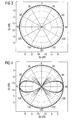
- Figure 3 shows the directivity function of the antenna arrangement 100 in the horizontal plane for seven different frequencies of electromagnetic radiation.
- the depicted frequencies are 2.379 MHz, 2.4 MHz, 2.421 MHz, 2.442 MHz, 2.463 MHz, 2.484 MHz and 2.505 MHz. Since these directivity functions are very close to each other they can hardly be resolved in Figure 3 .
- Figure 4 shows the directivity function of the antenna arrangement 100 in an elevation view.
- most of the radiation intensity is emitted into the horizontal plane given by the angular values -90° and 90°.
- there are also minor intensity peaks of electromagnetic radiation being emitted into directions having an angle of +45° and -45° with respect to the horizontal plane.
- the axis have a logarithmic scale these intensity peaks only represent comparatively little radiation intensity.
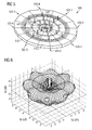
- FIG. 5 shows a further the Circular Yagi antenna arrangement 500 representing a modification of the antenna arrangement 100.
- the antenna arrangement 500 comprises a metal base plate 510, which has an upper surface 510a.
- the base plate 510 has a substantially circular size, which extends below the active antenna element 520 and below all passive antenna elements 521.
- LGPCY Large Ground Plane Circular Yagi
- the passive antenna elements 521 are arranged within 8 rows each extending radially outwards from the center of the antenna arrangement respectively from the active antenna element 520. As can be seen from Figure 5 each row comprises three passive antenna elements 521. Such an arrangement comprising eight rows each having three directors 521 will be denominated as an 8x3 director arrangement.
- the metal base plate 510 represents an electromagnetic mirror in particular for the electric potential being generated by the antenna arrangement 500.
- This mirror behavior has the advantage that compared to the antenna arrangement 100 shown in Figure 1 , the height of the antenna elements 520, 521 can be reduced by a factor of two. This is based on the matter of fact that the electromagnetic mirror has the same effect as a further antenna element arrangement, which is directly attached to the arrangement 500 in a mirror-inverted way. Therefore, by using a metal plate 510 as a base element the effective height of the antenna elements and; as a consequence, the effective height of the whole antenna arrangement 500 can be significantly reduced compared to an antenna arrangement being assembled on a dielectric base element.
- the metal base plate 510 results in a monopole-type active antenna element 520, which is feeding passive monopole-type directors 521.
- Figure 6 shows a three dimensional directivity function of the antenna arrangement 500.
- the illustrated directivity function has been calculated for electromagnetic radiation having a frequency of 2.442 GHz.
- the maximum gain is 4.2 dBi in certain directions seen in Figures 7 and 8 .
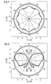
- Figure 7 shows the directivity function of the antenna arrangement 500 in the horizontal plane for seven different frequencies of electromagnetic radiation. Again, the depicted frequencies are 2.379 MHz, 2.4 MHz, 2.421 MHz, 2.442 MHz, 2.463 MHz, 2.484 MHz and 2.505 MHz. Since these directivity functions are very close to each other they can hardly be resolved in Figure 7 .
- Each of the depicted directivity functions exhibits eight bumps protruding outwardly. In between two neighboring bumps there is a dimple (minimum). Differences between the different frequency directivity functions can only be seen within the regions of one of the eight the dimples. The difference between the maximums and minimums in the antenna gain, ripple in the antenna gain, depends of the number of passive director element rows used in the antenna.
- Figure 8 shows the directivity function of the antenna arrangement 500 in an elevation view.
- most of the radiation intensity is emitted into a direction being oriented approximately 20° angularly offset with respect to the horizontal plane given by the angular values -90° and 90°.
- the metallic base plate 510 which has a diameter of approximately 350 mm, has a limited lateral dimension and therefore does not act as a perfect electromagnetic mirror, which would require an infinite lateral dimension.
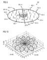
- FIG. 9 shows a further the Circular Yagi antenna arrangement 900 representing a modification of the antenna arrangement 500.
- the antenna arrangement 900 comprises a small metal base plate 915.
- the metal base plate 915 has a substantially circular size, which extends solely below the active antenna element 920.
- a dielectric base plate 910 which supports the passive antenna elements 921.
- SGPCY Small Ground Plane Circular Yagi
- the passive antenna elements 921 are arranged within twelve rows 925-1, 925-2, 925-3, 925-4, 925-5, 925-6, 925-7, 925-8, 925-9, 925-10, 925-11 and 925-12 each extending radially outwards from the center of the antenna arrangement respectively from the active antenna element 920.
- each row comprises four passive antenna elements 521.
- Such an arrangement comprising twelve rows each having four directors 921 will be denominated a 12x4 director arrangement.
- the length of the active antenna element 920 can be reduced by a factor of two compared to an antenna arrangement having no metal plate. Since the passive antenna elements are supported by a non conductive dielectric base element 910 the length of the directors 921 corresponds to the length of the directors 121 of the antenna arrangement 100 illustrated in Figure 1 . According to the embodiment described here the maximal diameter of the base element 910 is 469 mm.
- the SGPCY antenna arrangement 900 results in a monopole-type active antenna element 920, which in operation feeds the surrounding passive dipole-type directors 921.
- Figure 10 shows a three dimensional directivity function of the antenna arrangement 900.
- the illustrated directivity function has been calculated for electromagnetic radiation having a frequency of 2.442 GHz.
- the maximum gain is 6.2 dBi in certain horizontal directions.
- Figure 11 shows the directivity function of the antenna arrangement 900 in the horizontal plane for seven different frequencies of electromagnetic radiation.
- the depicted frequencies are again 2.379 MHz, 2.4 MHz, 2.421 MHz, 2.442 MHz, 2.463 MHz, 2.484 MHz and 2.505 MHz. Since also these directivity functions are very close they can hardly be resolved from each other in Figure 11 .
- Each of the depicted directivity functions exhibits twelve bumps protruding outwardly. In between two neighboring bumps there is a radially dimple. Differences between the different frequency directivity functions can only be seen within the regions of the above described dimples.
- Figure 12 shows the directivity function of the antenna arrangement 900 in an elevation view.
- most of the radiation intensity is emitted into the horizontal plane given by the angular values -90° and 90°.
- there are also minor intensity peaks of electromagnetic radiation being emitted into directions having an angle of +-45° with respect to the horizontal plane.
- the axis have a logarithmic scale these intensity peaks only represent comparatively little radiation intensity.
- Figure 13 shows a three dimensional directivity function of a SGPCY antenna arrangement, which is not explicitly depicted in the accompanying drawing.
- the antenna arrangement comprises a 12x3 director arrangement and a maximum diameter of 352 mm.
- the illustrated directivity function has been calculated again for electromagnetic radiation having a frequency of 2.442 GHz.
- the maximum gain is 4.7 dBi in certain horizontal directions.
- Figure 14 shows the directivity function of the above-mentioned SGPCY antenna arrangement having a 12x3 director arrangement in the horizontal plane.
- the directivity function is again depicted for the frequencies of 2.379 MHz, 2.4 MHz, 2.421 MHz, 2.442 MHz, 2.463 MHz, 2.484 MHz and 2.505 MHz.
- Each of the depicted directivity functions exhibits twelve bumps respectively protruding outwardly.
- Figure 15 shows the directivity function of the above-mentioned SGPCY antenna arrangement having a 12x3 director arrangement in an elevation view. Again most of the radiation intensity is emitted into the horizontal plane given by the angular values -90° and 90°. Further, there are again minor intensity peaks of electromagnetic radiation being emitted into directions having an angle of +45° or -45° with respect to the horizontal plane.
- Figure 16 shows a three dimensional directivity function of a further SGPCY antenna arrangement, which is also not explicitly depicted in the accompanying drawing.
- This antenna arrangement comprises an 8x2 director arrangement and a maximum diameter of 235 mm.
- the illustrated directivity function has been calculated again for electromagnetic radiation having a frequency of 2.442 GHz.
- the maximum gain is 4.4 dBi in certain horizontal directions.
- Figure 17 shows the directivity function of the above-mentioned SGPCY antenna arrangement having the 8x2 director arrangement in the horizontal plane.
- the directivity function is again depicted for the frequencies of 2.379 MHz, 2.4 MHz, 2.421 MHz, 2.442 MHz, 2.463 MHz, 2.484 MHz and 2.505 MHz.
- Each of the depicted directivity functions exhibits eight bumps protruding outwardly.
- Figure 18 shows the directivity function of the above-mentioned SGPCY antenna arrangement having the 8x2 director arrangement in an elevation view. Again most of the radiation intensity is emitted into the horizontal plane given by the angular values -90° and 90°.
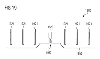
- FIG 19 shows an antenna arrangement 1900 representing a further modification of the Circular Yagi antenna arrangement.
- the antenna arrangement 1900 comprises a conductive ground plane 1955, which is spatially separated from the passive antenna elements 1921 and which laterally extends below all passive antenna elements 1921.
- the passive antenna elements respectively the directors 1921, which can be realized for instance by strips on vertical substrate pieces, are mounted to a not depicted dielectric support base element.
- the active antenna element respectively the feed element 1920 is a monopole-type antenna element.
- a feed connector 1960 is used to electrically connect the active antenna element 1920.
- the antenna arrangement 1900 has the advantage that it directs the beam nearer to the horizon as compared for instance the antenna arrangement 500 (see Figure 8 ), but a nearby ceiling does not disturb its performance as it is a case with the antenna arrangements 100 and 900 as presented in Figure 1 and Figure 9 , respectively.
- the antenna arrangement 1900 is very similar to the antenna arrangement 900 shown in Figure 9 , when employing the antenna arrangement 1900 a nearby ceiling and electronics under the conductive ground-plane 1955 are effectively shielded in a more controlled way.
Landscapes
- Aerials With Secondary Devices (AREA)
Priority Applications (1)
| Application Number | Priority Date | Filing Date | Title |
|---|---|---|---|
| EP08000022A EP2077604A1 (fr) | 2008-01-02 | 2008-01-02 | Agencement d'antenne en plusieurs lignes doté d'un profil de transmission et/ou de réception bidimensionnel omnidirectionnel |
Applications Claiming Priority (1)
| Application Number | Priority Date | Filing Date | Title |
|---|---|---|---|
| EP08000022A EP2077604A1 (fr) | 2008-01-02 | 2008-01-02 | Agencement d'antenne en plusieurs lignes doté d'un profil de transmission et/ou de réception bidimensionnel omnidirectionnel |
Publications (1)
| Publication Number | Publication Date |
|---|---|
| EP2077604A1 true EP2077604A1 (fr) | 2009-07-08 |
Family
ID=39284114
Family Applications (1)
| Application Number | Title | Priority Date | Filing Date |
|---|---|---|---|
| EP08000022A Ceased EP2077604A1 (fr) | 2008-01-02 | 2008-01-02 | Agencement d'antenne en plusieurs lignes doté d'un profil de transmission et/ou de réception bidimensionnel omnidirectionnel |
Country Status (1)
| Country | Link |
|---|---|
| EP (1) | EP2077604A1 (fr) |
Cited By (4)
| Publication number | Priority date | Publication date | Assignee | Title |
|---|---|---|---|---|
| US20140225794A1 (en) * | 2012-12-07 | 2014-08-14 | Korea Advanced Institute Of Science And Technology | Method and apparatus for beamforming |
| CN105140628A (zh) * | 2015-07-20 | 2015-12-09 | 华为技术有限公司 | 一种微带全向天线及通信器件 |
| CN111277298A (zh) * | 2020-01-21 | 2020-06-12 | Oppo广东移动通信有限公司 | 客户前置设备 |
| CN113161731A (zh) * | 2020-01-22 | 2021-07-23 | 华为技术有限公司 | 天线和通讯设备 |
Citations (7)
| Publication number | Priority date | Publication date | Assignee | Title |
|---|---|---|---|---|
| US3109175A (en) * | 1960-06-20 | 1963-10-29 | Lockheed Aircraft Corp | Rotating beam antenna utilizing rotating reflector which sequentially enables separate groups of directors to become effective |
| EP0172626A1 (fr) * | 1984-07-02 | 1986-02-26 | Canadian Patents and Development Limited | Dispositif d'antenne adaptive en direction |
| EP0812026A2 (fr) * | 1996-06-05 | 1997-12-10 | International Business Machines Corporation | Système et procédés de communication utilisant un réseau d'antennes à directivité à contrÔle réactif |
| US20020158798A1 (en) * | 2001-04-30 | 2002-10-31 | Bing Chiang | High gain planar scanned antenna array |
| WO2004107497A2 (fr) * | 2003-05-23 | 2004-12-09 | Ipr Licensing, Inc. | Antenne a gain eleve pour applications sans fil |
| WO2005055365A1 (fr) * | 2003-11-27 | 2005-06-16 | Centre National De La Recherche Scientifique (Cnrs) | Antenne configurable et orientable station de base correspondante |
| EP1804335A1 (fr) * | 2004-09-30 | 2007-07-04 | Toto Ltd. | Antenna microruban et detecteur de frequences elevees l'utilisant |
-
2008
- 2008-01-02 EP EP08000022A patent/EP2077604A1/fr not_active Ceased
Patent Citations (7)
| Publication number | Priority date | Publication date | Assignee | Title |
|---|---|---|---|---|
| US3109175A (en) * | 1960-06-20 | 1963-10-29 | Lockheed Aircraft Corp | Rotating beam antenna utilizing rotating reflector which sequentially enables separate groups of directors to become effective |
| EP0172626A1 (fr) * | 1984-07-02 | 1986-02-26 | Canadian Patents and Development Limited | Dispositif d'antenne adaptive en direction |
| EP0812026A2 (fr) * | 1996-06-05 | 1997-12-10 | International Business Machines Corporation | Système et procédés de communication utilisant un réseau d'antennes à directivité à contrÔle réactif |
| US20020158798A1 (en) * | 2001-04-30 | 2002-10-31 | Bing Chiang | High gain planar scanned antenna array |
| WO2004107497A2 (fr) * | 2003-05-23 | 2004-12-09 | Ipr Licensing, Inc. | Antenne a gain eleve pour applications sans fil |
| WO2005055365A1 (fr) * | 2003-11-27 | 2005-06-16 | Centre National De La Recherche Scientifique (Cnrs) | Antenne configurable et orientable station de base correspondante |
| EP1804335A1 (fr) * | 2004-09-30 | 2007-07-04 | Toto Ltd. | Antenna microruban et detecteur de frequences elevees l'utilisant |
Non-Patent Citations (1)
| Title |
|---|
| MIGLIORE M D ET AL: "A Simple and Robust Adaptive Parasitic Antenna", IEEE TRANSACTIONS ON ANTENNAS AND PROPAGATION, IEEE SERVICE CENTER, PISCATAWAY, NJ, US, vol. 53, no. 10, October 2005 (2005-10-01), pages 3262 - 3272, XP011140098, ISSN: 0018-926X * |
Cited By (9)
| Publication number | Priority date | Publication date | Assignee | Title |
|---|---|---|---|---|
| US20140225794A1 (en) * | 2012-12-07 | 2014-08-14 | Korea Advanced Institute Of Science And Technology | Method and apparatus for beamforming |
| US9728862B2 (en) * | 2012-12-07 | 2017-08-08 | Korea Advanced Institute Of Science And Technology | Method and apparatus for beamforming |
| CN105140628A (zh) * | 2015-07-20 | 2015-12-09 | 华为技术有限公司 | 一种微带全向天线及通信器件 |
| CN105140628B (zh) * | 2015-07-20 | 2018-07-03 | 华为技术有限公司 | 一种微带全向天线及通信器件 |
| CN111277298A (zh) * | 2020-01-21 | 2020-06-12 | Oppo广东移动通信有限公司 | 客户前置设备 |
| WO2021147747A1 (fr) * | 2020-01-21 | 2021-07-29 | Oppo广东移动通信有限公司 | Équipement de locaux d'abonné |
| CN111277298B (zh) * | 2020-01-21 | 2021-11-09 | Oppo广东移动通信有限公司 | 客户前置设备 |
| CN113161731A (zh) * | 2020-01-22 | 2021-07-23 | 华为技术有限公司 | 天线和通讯设备 |
| CN113161731B (zh) * | 2020-01-22 | 2023-02-10 | 华为技术有限公司 | 天线和通讯设备 |
Similar Documents
| Publication | Publication Date | Title |
|---|---|---|
| US12088017B2 (en) | Radiating element, antenna assembly and base station antenna | |
| US11018408B2 (en) | Antenna apparatus in wireless communication device | |
| KR102172187B1 (ko) | 이동통신 서비스용 옴니 안테나 | |
| WO2020068464A1 (fr) | Antenne avec métamatériau à gradient d'indice | |
| CN107359424B (zh) | 一种阵列天线 | |
| CN103390795A (zh) | 一种方向图具有多种可重构特性的天线 | |
| CN105206946A (zh) | 室内双极化全向吸顶天线 | |
| EP2631991A1 (fr) | Antenne microruban | |
| CN110011026B (zh) | 一种天线单元、天线阵列和基站 | |
| CN116325360A (zh) | 具有支持高频带掩蔽的紧凑双极化盒形偶极子辐射元件的基站天线 | |
| US20230163462A1 (en) | Antenna device with improved radiation directivity | |
| KR20120078646A (ko) | 450 MHz 도너 안테나 | |
| US20240195081A1 (en) | Cross-dipole radiating elements having helix-shaped dipole arms and base station antennas having such radiating elements | |
| WO2019100376A1 (fr) | Antenne réseau omnidirectionnelle et son procédé de formation de faisceau | |
| CN108598699B (zh) | 垂直极化全波振子阵列天线以及定向辐射天线 | |
| US11239544B2 (en) | Base station antenna and multiband base station antenna | |
| KR20230059267A (ko) | 다중 대역 다중 배열 기지국 안테나 | |
| CN107611601B (zh) | 小型化高增益双极化全向天线 | |
| US11646502B2 (en) | Multi-band base station antenna | |
| EP4583309A1 (fr) | Terminal de communication avec éléments rayonnants d'antenne entrelacés et autonomes | |
| Shishkin | Research of a wideband dual-polarization microstrip antenna array on a suspended substrate with irregular arrangement of elements | |
| CN103887600B (zh) | 无线覆盖天线单元、天线组件及多天线组件 | |
| CN219917579U (zh) | 一种全向天线 | |
| CN104167611B (zh) | 一种双向双极化天线 | |
| CN115954661B (zh) | 一种具有360°周向波束覆盖的可重构微带天线 |
Legal Events
| Date | Code | Title | Description |
|---|---|---|---|
| PUAI | Public reference made under article 153(3) epc to a published international application that has entered the european phase |
Free format text: ORIGINAL CODE: 0009012 |
|
| AK | Designated contracting states |
Kind code of ref document: A1 Designated state(s): AT BE BG CH CY CZ DE DK EE ES FI FR GB GR HR HU IE IS IT LI LT LU LV MC MT NL NO PL PT RO SE SI SK TR |
|
| AX | Request for extension of the european patent |
Extension state: AL BA MK RS |
|
| STAA | Information on the status of an ep patent application or granted ep patent |
Free format text: STATUS: THE APPLICATION HAS BEEN REFUSED |
|
| 18R | Application refused |
Effective date: 20090506 |