EP2077705B1 - Support variable destiné au montage sur deux profilés de support verticaux d'un rack et procédé de montage - Google Patents
Support variable destiné au montage sur deux profilés de support verticaux d'un rack et procédé de montage Download PDFInfo
- Publication number
- EP2077705B1 EP2077705B1 EP08171851.2A EP08171851A EP2077705B1 EP 2077705 B1 EP2077705 B1 EP 2077705B1 EP 08171851 A EP08171851 A EP 08171851A EP 2077705 B1 EP2077705 B1 EP 2077705B1
- Authority
- EP
- European Patent Office
- Prior art keywords
- carrier
- vertical
- variable
- snap
- profile
- Prior art date
- Legal status (The legal status is an assumption and is not a legal conclusion. Google has not performed a legal analysis and makes no representation as to the accuracy of the status listed.)
- Not-in-force
Links
Images




Classifications
-
- A—HUMAN NECESSITIES
- A47—FURNITURE; DOMESTIC ARTICLES OR APPLIANCES; COFFEE MILLS; SPICE MILLS; SUCTION CLEANERS IN GENERAL
- A47B—TABLES; DESKS; OFFICE FURNITURE; CABINETS; DRAWERS; GENERAL DETAILS OF FURNITURE
- A47B88/00—Drawers for tables, cabinets or like furniture; Guides for drawers
-
- H—ELECTRICITY
- H05—ELECTRIC TECHNIQUES NOT OTHERWISE PROVIDED FOR
- H05K—PRINTED CIRCUITS; CASINGS OR CONSTRUCTIONAL DETAILS OF ELECTRIC APPARATUS; MANUFACTURE OF ASSEMBLAGES OF ELECTRICAL COMPONENTS
- H05K7/00—Constructional details common to different types of electric apparatus
- H05K7/14—Mounting supporting structure in casing or on frame or rack
- H05K7/1421—Drawers for printed circuit boards
-
- H—ELECTRICITY
- H05—ELECTRIC TECHNIQUES NOT OTHERWISE PROVIDED FOR
- H05K—PRINTED CIRCUITS; CASINGS OR CONSTRUCTIONAL DETAILS OF ELECTRIC APPARATUS; MANUFACTURE OF ASSEMBLAGES OF ELECTRICAL COMPONENTS
- H05K7/00—Constructional details common to different types of electric apparatus
- H05K7/14—Mounting supporting structure in casing or on frame or rack
- H05K7/1485—Servers; Data center rooms, e.g. 19-inch computer racks
- H05K7/1488—Cabinets therefor, e.g. chassis or racks or mechanical interfaces between blades and support structures
-
- A—HUMAN NECESSITIES
- A47—FURNITURE; DOMESTIC ARTICLES OR APPLIANCES; COFFEE MILLS; SPICE MILLS; SUCTION CLEANERS IN GENERAL
- A47B—TABLES; DESKS; OFFICE FURNITURE; CABINETS; DRAWERS; GENERAL DETAILS OF FURNITURE
- A47B96/00—Details of cabinets, racks or shelf units not covered by a single one of groups A47B43/00 - A47B95/00; General details of furniture
- A47B96/06—Brackets or similar supporting means for cabinets, racks or shelves
-
- Y—GENERAL TAGGING OF NEW TECHNOLOGICAL DEVELOPMENTS; GENERAL TAGGING OF CROSS-SECTIONAL TECHNOLOGIES SPANNING OVER SEVERAL SECTIONS OF THE IPC; TECHNICAL SUBJECTS COVERED BY FORMER USPC CROSS-REFERENCE ART COLLECTIONS [XRACs] AND DIGESTS
- Y10—TECHNICAL SUBJECTS COVERED BY FORMER USPC
- Y10T—TECHNICAL SUBJECTS COVERED BY FORMER US CLASSIFICATION
- Y10T24/00—Buckles, buttons, clasps, etc.
- Y10T24/44—Clasp, clip, support-clamp, or required component thereof
Definitions
- the invention relates to a Variozier for mounting on two vertical support profiles of a rack, wherein the vertical support profiles of the rack have openings in a standardized grid, the Variocken on the openings on the vertical support profiles can be fixed and the Vario support has a locking device which during assembly in one of the openings on the vertical support profiles automatically locked.
- the invention relates to a method for mounting a Varioziers on two vertical support profiles of a rack. Furthermore, an arrangement of such a Varioziers and such a rack will be described.
- a rack mount kit (RMK) is required.
- This carrier allows you to pull a computer server out of the rack for maintenance without disassembling the fasteners.
- the system carrier consists of a left and a right carrier.
- the Variolang is a variant thereof, which allows a user-adjustable length, the length depends on the distance between the support profiles of a rack.
- the openings in the vertical support profiles in Europe have square openings measuring 9 x 9 mm and 9.5 x 9.5 mm, respectively. In the US, the openings are also standardized, with a here Round hole grid is used. So far, the support systems or the Varioong be manually bolted to the vertical support profiles. In order to simplify the assembly, it is desirable to be able to attach the Varioong without screws to the vertical support profiles of the racks.
- the US 6,230,903 B1 discloses an alternative solution for a screwless mounting of a Varioongs.
- the document are screwed to a telescopic rail two rails, which also have end inwardly projecting extensions and can engage in the openings of the vertical support profiles from the outside.
- the rails are fixed to a continuous rigid part of the telescopic rail.
- the exemplary embodiment according to FIG. 5 of the document is in principle constructed analogously, the extensions pointing from the inside outwards, so that they are inserted through the openings into the vertical carrier profiles for fixing the telescopic rail in this direction as well.
- the Variolang has a locking device which automatically locks when inserted into one of the openings on the vertical support profiles.
- the latching device is arranged on a front side of the Varioèves and is designed as a spring-loaded hook, which is inserted during assembly of the Varioèves from the inside through an opening of the vertical support profile and engages in the mounted state behind the edge of the opening.
- On the opposite end face of the Varioèves another latching device or a projecting beam is arranged, which can be inserted into the opening of the vertical support profile.
- one end of the Varioongs is first inserted into the openings of the vertical support profile and then the second end inserted through the adjustable length of the Varioèves.
- the invention is therefore based on the object to describe a solution for mounting a Varioziers on vertical support profiles of a rack that allows easier production and easier installation of the Variopars.
- the Variozier opposite the locking device has at least one rigidly connected to the Vario support holding hook for hanging in one of the openings of a vertical support profile, so that the Variocken can be suspended via the retaining hooks in the opening, wherein the retaining hook in mounted state engages laterally behind a vertical edge of the designated opening of the vertical beam profile.
- the Varioong on a resilient length compensation wherein the resilient length compensation can be stretched and the Vario support can be pivoted about the retaining hook in a horizontal plane in the direction of the opposite vertical support profile and then the resilient length compensation can be relaxed and the Locking device can lock with one of the openings on the opposite vertical support profile.
- the variator is held at an acute angle to an imaginary axis Y-Y 'extending between the two vertical support profiles so that the retention hook can be passed through the opening of the first vertical support profile.
- the Varioson is further moved around this holding hook in a horizontal plane or pivoted, wherein the second end of the Varioèves having a locking device is brought in the vicinity of the second vertical support profile. That is, the second end of the zoom carrier moves along a circular path, with the center of the circle being the retaining hooks.
- the Variolang is preferably equipped with a resilient length compensation. If the second end of the Varioanders is shortly before the second vertical support profile, and the Vario support is almost on the axis Y-Y ', the length compensation is stretched and the second end of the Varioanders further pivoted until the latch engages in an opening of the second vertical support profile. After pivoting the length compensation is preferably relaxed. By a closing spring which engages in the vertical support profile, a re-unlocking of the length compensation is prevented.
- the Varioong preferably has at the two end faces retaining hooks which are rigidly connected to the Variotextured.
- the two faces of the Variorelys are located at the two ends of the Variotextureds and are the front surfaces of the Variounlesss, each directed outward in the direction of the largest dimension of the Varioèves, namely the length.
- the retaining hooks on one end face engage laterally in one direction and the retaining hooks on the other end face laterally in the opposite direction.
- the retaining hooks are directed so that the Vario support can be hooked at one end in a first vertical beam profile and then can be pivoted in a horizontal plane until the other, second end is just before the second vertical beam profile.
- the retaining hooks at the second end of the Varioziers are directed in the pivoting direction.
- at least one centering element is arranged on the end face opposite the latching device. During the pivoting of the Varioongs the centering element is guided through an opening of the vertical support profile. The centering prevents slipping out of the retaining hooks and other movements of the Varioèves relative to the first vertical support profile.
- the centering element is preferably designed as a horizontal tab, wherein the locking device opposite retaining hooks engage vertically in the openings of the vertical support profile.
- the latching device is designed as a spring element which is relaxed in the latched state and abuts a vertical edge of an opening of the second vertical support profile.
- the spring element also serves to stabilize the Variostrongs relative to the vertical support profile.
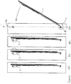
- a Variolang 1 is hooked at a first end by means of two rigidly connected to the Vario support 1 holding hooks 2 in two openings 3 of a first vertical support section 4a.
- the Vario support 1 projects at an acute angle from an imaginary axis YY 'which extends between two vertical support profiles 4a, 4b.
- the variable carrier 1 is then pivoted in the direction of the second vertical carrier profile 4b in a horizontal plane, as in FIG. 1a indicated by an arrow.
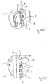
- FIG. 2a An enlarged detail A of the retaining hooks 2 of the Vario support 1 mounted in the openings 3 of the vertical support profile 4a in this step of the assembly process is shown in FIG. 2a shown.
- the two retaining hooks 2 are from the inside of the vertical support section 4a, ie from the from the other vertical support profile 4b facing side of the support section 4a, mounted.
- FIG. 2a shows the section from the outside of the first vertical support profile 4a.
- the two retaining hooks 2 engage laterally behind each vertical edge of the corresponding opening 3 of the vertical support section 4a, but are not yet sitting positively.
- the retaining hooks 2 are directed counter to the pivoting direction, so that they grip by the pivoting solid or more form-fitting behind the corresponding edge of the opening 3 and are not loosened.
- the Vario support 1 For stabilization or centering of the Vario support 1 also on the front side two horizontal tabs 5a and 5b, which are guided through the openings 3 of the first vertical support profile 4a.
- the horizontal tabs 5a and 5b are guided in the same two openings 3 as the retaining hooks 2.
- the lower horizontal tab 5a bears against the lower edge of the lower opening 3 and the upper horizontal tab 5b abuts against the upper edge of the upper opening 3.
- a pawl 6 can be installed on this end face of the Varioongs 1 as an additional safeguard against slipping out of the retaining hooks 2.
- the Variozier 1 is first according to FIG. 1a pivoted in the arrow direction in a horizontal plane until the zoom carrier 1 is almost on the imaginary axis YY '. This position is in FIG. 1b shown.
- the holding hook opposite end of the Varioanders, which has a latching device, is just before the inside of the second carrier profile 4b.
- FIG. 2b An enlarged detail B of the latching device having the end of the Varioongs 1 is in FIG. 2b shown.
- the latching device has a spring element 7 and two holding hooks 8 rigidly connected to the variable carrier 1.
- the Varioong 1 is also equipped with a resilient length compensation 9. In this step of the assembly process, the length compensation 9 is tensioned so that the retaining hooks 8 of the latching device can be guided through two corresponding openings 3 of the second vertical support profile 4b.
- FIG. 1c This further step is in Figure 1c and as an enlarged section C in Figure 2c shown.
- the front side of the Varioleys 1 is now on the inside of the second vertical support section 4b.
- the vertical edge of an opening 3 of a vertical support profile 4a or 4b closest to the variable support 1 is referred to as an outer vertical edge 3a.
- the outer edge of the opposite vertical edge of an opening 3 is referred to as inner vertical edge 3b.
- the retaining hooks 8 are directed so that they can each grip laterally behind a vertical edge 3b of the openings 3 in the pivoting direction. In the position according to Figure 2c however, the retaining hooks 8 do not yet grip behind the respective edge 3b of the openings 3, but lie against the vertical edge 3a of the openings 3 opposite this.
- FIG. 2e shows the same section D1, but now viewed from the outside of the vertical support profile 4b.
- the retaining hooks 8 of the latching device dive through the openings 3 of the vertical support profile 4b and, after latching, finally engage behind the outside of the vertical support profile 4b.
- the retaining hooks 8 lie in a form-fitting manner against an inner vertical edge 3b of their corresponding openings 3.
- the spring element 7 is positively against the opposite vertical edge 3a of its opening 3.
- FIG. 1d with D2 marked section of the first carrier profile 4a is in an enlarged form in FIG. 2f shown.
- the optional pawl 6 is snapped, the retaining hooks 2 are completely submerged through their openings 3 and engage behind the outer vertical edge 3a of the corresponding openings 3 in a form-fitting manner.
- the horizontal tabs 5a, 5b abut against the lower edge or upper edge of the openings 3 and stabilize the Variocken 1 vertically and horizontally.
- the assembly process steps of FIGS. 1a to 1d and 2a to 2f are again in the FIGS. 3a to 3d shown, but now in plan view.
- FIG. 3a is, as already described, the Variozier 1 hooked by means of the retaining hooks 2 in the first vertical support section 4a, so that the Vario support 1 protrudes at an acute angle from the imaginary axis YY ', which in FIG. 3a is indicated by dashed lines.
- the retaining hooks 2 are suspended in corresponding openings 3 of the vertical support profile 4a, but are not yet positively locking on the outer vertical edge 3a of their openings 3.
- the in FIG. 3a The section marked with E is in enlarged form in FIG. 4a shown.
- FIG. 3b After pivoting the Varioziers 1 in the arrow direction it is almost on the imaginary axis Y-Y ', as in FIG. 3b is shown.
- the in FIG. 3b The section marked F is in FIG. 4b shown in enlarged form.
- the retaining hooks 8 of the locking device just before the corresponding openings 3 of the second vertical support section 4b.
- Figure 4e a sectional view of the section H for clearer representation of the locked position of the Variolangs 1 on the vertical support section 4b.
- the retaining hooks 8 bear against the vertical edge 3b of their openings 3 and engage behind the vertical support profile 4b.
Landscapes
- Engineering & Computer Science (AREA)
- Microelectronics & Electronic Packaging (AREA)
- Computer Hardware Design (AREA)
- General Engineering & Computer Science (AREA)
- Furniture Connections (AREA)
- Clamps And Clips (AREA)
- Workshop Equipment, Work Benches, Supports, Or Storage Means (AREA)
- Supports Or Holders For Household Use (AREA)
Claims (8)
- Support variable (1) destiné au montage au niveau de deux profilés de support (4a, 4b) verticaux d'un rack, dans lequel- les deux profilés de support (4a, 4b) verticaux du rack présentent des ouvertures (3) selon une trame standardisée,- le support variable (1) peut être fixé par l'intermédiaire des ouvertures (3) au niveau des profilés de support (4a, 4b) verticaux, et- le support variable (1) présente un dispositif d'enclenchement, lequel peut être enclenché de manière automatique lors du montage dans une des ouvertures (3) au niveau des profilés de support (4a, 4b) verticaux,
caractérisé en ce que
le support variable (1)- présente, en vis-à-vis du dispositif d'enclenchement, au moins un crochet de maintien (2) relié de manière rigide au support variable (1), destiné à être suspendu dans une des ouvertures (3) d'un profilé de support (4a) vertical des deux profilés de support (4a, 4b) verticaux, de sorte que le support variable (1) peut être suspendu par l'intermédiaire du crochet de maintien (2) dans l'ouverture (3), dans lequel le crochet de maintien (2) s'engage dans l'état monté latéralement derrière un bord vertical de l'ouverture (3) prévue à cet effet de l'un profilé de support (4a) vertical et- présente une compensation de longueur (9) sur ressorts, dans lequel la compensation de longueur (9) sur ressorts peut être tendue et le support variable (1) peut être pivoté autour du crochet de maintien (2) dans un plan horizontal en direction de l'autre profilé de support (4b) vertical faisant face des deux profilés de support (4a, 4b) verticaux et pour finir la compensation de longueur(9) sur ressorts peut être détendue et le dispositif d'enclenchement peut s'enclencher avec une des ouvertures (3) au niveau de l'autre profilé de support (4b) vertical faisant face. - Support variable (1) selon la revendication 1,
caractérisé en ce que
le support variable (1) présente au niveau des deux côtés frontaux des crochets de maintien (2, 8), qui sont reliés de manière rigide au support variable (1). - Support variable (1) selon la revendication 2,
caractérisé en ce que
les crochets de maintien (2, 8) s'engagent au niveau d'un côté frontal latéralement dans une direction et les crochets de maintien (2, 8) s'engagent au niveau de l'autre côté frontal latéralement dans le sens opposé. - Support variable (1) selon l'une quelconque des revendications 1 à 3,
caractérisé en ce que
le dispositif d'enclenchement est disposé au niveau d'un côté frontal du support variable (1) et au moins un élément de centrage est disposé au niveau du côté frontal faisant face. - Support variable (1) selon la revendication 4,
caractérisé en ce que
l'élément de centrage est réalisé sous la forme d'une patte (5) horizontale et les crochets de maintien (2) faisant face au dispositif d'enclenchement viennent en prise de manière verticale avec les ouvertures (3) d'un profilé de support (4a) vertical. - Support variable (1) selon l'une quelconque des revendications 1 à 5,
caractérisé en ce que
le dispositif d'enclenchement est réalisé sous la forme d'un élément ressort (7), qui est détendu dans l'état enclenché et vient buter au niveau d'un bord (3a, 3b) vertical d'une ouverture (3) de l'autre profilé de support (4b) vertical. - Procédé servant au montage d'un support variable (1) selon l'une quelconque des revendications 1 à 6 au niveau de deux profilés de support (4a, 4b) verticaux d'un rack,
caractérisé en ce que- le support variable (1) est maintenu de telle sorte avec le crochet de maintien (2) faisant face au dispositif d'enclenchement de manière dirigée sur un premier profilé de support (4a) vertical que le support variable (1) se situe vu d'en haut selon un angle aigu par rapport à un axe imaginaire Y-Y', qui s'étend entre le premier profilé de support (4a) vertical faisant face et un deuxième profilé de support (4b) vertical faisant face au premier,- le crochet de maintien (2) est guidé dans une ouverture (3) du premier profilé de support (4a) vertical et y est suspendu,- une compensation de longueur (9) sur ressorts est tendue au niveau du support variable (1),- le support variable (1) est pivoté autour du crochet de maintien (2) dans un plan horizontal en direction du deuxième profilé de support (4b) vertical jusqu'à ce qu'il se trouve peu avant l'axe imaginaire Y-Y',- la compensation de longueur sur ressorts est détendue et la longueur du support variable (1) est allongée jusqu'à ce que le dispositif d'enclenchement puisse s'enclencher dans une ouverture (3) du deuxième profilé de support (4b) vertical, et- le dispositif d'enclenchement est enclenché dans l'ouverture (3) du deuxième profilé de support (4b) vertical. - Ensemble avec un support variable (1) selon l'une quelconque des revendications 1 à 6 et un rack avec deux profilés de support (4a, 4b) verticaux, dans lequel- les profilés de support (4a, 4b) verticaux du rack présentent des ouvertures (3) selon une trame standardisée, et- le support variable (1) est fixé par l'intermédiaire des ouvertures (3) par l'entremise du dispositif d'enclenchement et de l'au moins un crochet de maintien (2) faisant face au dispositif d'enclenchement au niveau des profilés de support (4a, 4) verticaux.
Applications Claiming Priority (1)
| Application Number | Priority Date | Filing Date | Title |
|---|---|---|---|
| DE102008003071A DE102008003071B4 (de) | 2008-01-03 | 2008-01-03 | Varioträger zur Montage an zwei vertikalen Trägerprofilen eines Racks sowie Montageverfahren |
Publications (3)
| Publication Number | Publication Date |
|---|---|
| EP2077705A2 EP2077705A2 (fr) | 2009-07-08 |
| EP2077705A3 EP2077705A3 (fr) | 2010-06-23 |
| EP2077705B1 true EP2077705B1 (fr) | 2019-10-23 |
Family
ID=40512556
Family Applications (1)
| Application Number | Title | Priority Date | Filing Date |
|---|---|---|---|
| EP08171851.2A Not-in-force EP2077705B1 (fr) | 2008-01-03 | 2008-12-16 | Support variable destiné au montage sur deux profilés de support verticaux d'un rack et procédé de montage |
Country Status (3)
| Country | Link |
|---|---|
| US (1) | US20090173706A1 (fr) |
| EP (1) | EP2077705B1 (fr) |
| DE (1) | DE102008003071B4 (fr) |
Families Citing this family (1)
| Publication number | Priority date | Publication date | Assignee | Title |
|---|---|---|---|---|
| DE102011117222B4 (de) * | 2011-10-28 | 2013-05-08 | Fujitsu Technology Solutions Intellectual Property Gmbh | Universalträger zur Montage an vertikalen Trägerprofilen eines Racks sowie Anordnung mit einem derartigen Universalträger und vertikalen Trägerprofilen eines Racks |
Family Cites Families (26)
| Publication number | Priority date | Publication date | Assignee | Title |
|---|---|---|---|---|
| DE19507437C1 (de) * | 1995-03-03 | 1996-05-15 | Loh Kg Rittal Werk | Vorrichtung zum Verbinden einer im wesentlichen U-förmigen Montageschiene mit einem Rahmenschenkel eines Rahmengestelles eines Schaltschrankes |
| US5833337A (en) * | 1997-05-09 | 1998-11-10 | Sequent Computer Systems, Inc. | Self-retaining rack slide |
| US6230903B1 (en) * | 1999-10-27 | 2001-05-15 | Hewlett-Packard Company | Snap-on rack slide mounting system |
| US6948691B2 (en) * | 2000-03-17 | 2005-09-27 | Jonathan Manufacturing Corporation | Computer server mounting apparatus |
| DE10104216A1 (de) * | 2001-01-31 | 2002-08-01 | Haendler Gmbh & Co Kg Elektro | Rastbare Moduleinheit für Schaltschränke |
| US6622873B2 (en) * | 2001-06-20 | 2003-09-23 | International Business Machines Corporation | Self-aligning, single person installable rack rail/alignment plate assembly |
| US6976745B2 (en) * | 2001-09-19 | 2005-12-20 | Hewlett-Packard Development Company, L.P. | Snap-on slide and rail assembly |
| US6702412B2 (en) * | 2001-09-19 | 2004-03-09 | Hewlett-Packard Development Company, L.P. | Expandable slide and rail assembly for a rack and method of installing same |
| US6659577B2 (en) * | 2001-12-06 | 2003-12-09 | Hewlett-Packard Development Company, L.P. | Dual flat springs for tool-less slide installation |
| US6739682B2 (en) * | 2002-02-07 | 2004-05-25 | Shoei-Yuan Shih | Slide rail structure for case cabinets |
| US6615992B1 (en) * | 2002-03-11 | 2003-09-09 | Hewlett-Packard Development Company L.P. | Adjustable rackmount assembly |
| US6926378B2 (en) * | 2002-08-15 | 2005-08-09 | General Devices Co., Inc. | Support system for telescoping slide assembly |
| US6891727B2 (en) * | 2002-08-21 | 2005-05-10 | International Business Machines Corporation | Apparatus and system to mount a device to a rack |
| US6935521B2 (en) * | 2002-09-23 | 2005-08-30 | International Business Machines Corporation | Adjustable apparatus to support an electronic device within a rack |
| US6840388B2 (en) * | 2002-10-28 | 2005-01-11 | Hewlett-Packard Development Company, L.P. | Tool-less rack mounting system |
| US6866154B2 (en) * | 2002-12-03 | 2005-03-15 | Dell Products L.P. | Tool-less attachment bracket |
| TWM255624U (en) * | 2003-12-30 | 2005-01-11 | King Slide Works Co Ltd | Positioning device for sliding track bracket |
| US6929339B1 (en) * | 2004-02-26 | 2005-08-16 | General Devices Co., Inc. | Latch controller for quick-mount support for telescoping slide |
| US7281694B2 (en) * | 2004-06-14 | 2007-10-16 | Hewlett-Packard Development Company, L.P. | Mounting bracket |
| US20060152115A1 (en) * | 2005-01-07 | 2006-07-13 | William Dubon | Adjustable reinforcing bracket for telescoping slide rail assembly |
| US20060283816A1 (en) * | 2005-06-21 | 2006-12-21 | Moore David C | Rack-mounted bracket assembly |
| US7494101B2 (en) * | 2005-08-18 | 2009-02-24 | Protrend Co., Ltd | Hook-on type rail |
| US7699279B2 (en) * | 2006-09-20 | 2010-04-20 | King Slide Works Co., Ltd. | Slide bracket |
| DE102007010042B3 (de) * | 2007-03-01 | 2008-09-04 | Fujitsu Siemens Computers Gmbh | Verschlusselement |
| US7934607B2 (en) * | 2007-03-20 | 2011-05-03 | Dell Products L.P. | Universal rack mount mechanism |
| US7762411B2 (en) * | 2007-10-17 | 2010-07-27 | International Business Machines Corporation | Tool-less rack rail system incorporating clamping mechanism |
-
2008
- 2008-01-03 DE DE102008003071A patent/DE102008003071B4/de not_active Expired - Fee Related
- 2008-12-16 EP EP08171851.2A patent/EP2077705B1/fr not_active Not-in-force
-
2009
- 2009-01-02 US US12/348,173 patent/US20090173706A1/en not_active Abandoned
Non-Patent Citations (1)
| Title |
|---|
| None * |
Also Published As
| Publication number | Publication date |
|---|---|
| EP2077705A3 (fr) | 2010-06-23 |
| EP2077705A2 (fr) | 2009-07-08 |
| DE102008003071B4 (de) | 2009-10-22 |
| US20090173706A1 (en) | 2009-07-09 |
| DE102008003071A1 (de) | 2009-07-16 |
Similar Documents
| Publication | Publication Date | Title |
|---|---|---|
| EP1064707A1 (fr) | Baie destinee a une armoire de distribution | |
| EP3572605A1 (fr) | Ensemble charnière pour un boîtier d'armoire de distribution et boîtier d'armoire de distribution correspondant | |
| EP3649353B1 (fr) | Système de fixation | |
| EP2820721B1 (fr) | Dispositif de fermeture d'un boîtier d'un connecteur enfichable | |
| EP1965625B1 (fr) | Support variable | |
| DE10240999B4 (de) | Vorrichtung zum winkligen Verbinden von Montageschienen | |
| DE102012007771C5 (de) | Montageplattenhalter für einen Schaltschrank sowie ein Befestigungsmittel zur Verwendung bei diesem | |
| DE202010007139U1 (de) | Vorrichtung zur Befestigung eines Moduls zur Nutzung von Sonnenenergie | |
| EP2077705B1 (fr) | Support variable destiné au montage sur deux profilés de support verticaux d'un rack et procédé de montage | |
| EP2767659B1 (fr) | Guide à barres rondes réglable en hauteur | |
| DE102012106406A1 (de) | Fixierungsanordnung und Schubkasten | |
| DE102011009734A1 (de) | Rasthalteelement für die reversible Befestigung von Bauteilen, insb. für die Wand- oder Deckenmontage von Bildwandsystemen | |
| DE102016125098A1 (de) | Einhängegestell für ein Gargerät sowie Gargerät | |
| DE202007008150U1 (de) | Befestigungsvorrichtung für Solarmodule | |
| DE8802894U1 (de) | Vorrichtung zur Befestigung von Abstands- und/oder Führungshalter auf gelochten Tragschienen für elektrische Verteileranlagen | |
| EP3931924B1 (fr) | Assemblage avec une armoire électrique et au moins une barre multiprise | |
| DE202009012416U1 (de) | Befestigungsvorrichtung zur Anordnung einer Torzarge an einer Wand | |
| DE202009010497U1 (de) | Winkel zur Befestigung eines Bauelementes | |
| DE202018104585U1 (de) | Haltevorrichtung für eine Glasscheibe sowie Halteanordnung und Glaswandanordnung | |
| WO2016004966A1 (fr) | Ensemble de rails de guidage et porte sectionnelle | |
| DE202024107021U1 (de) | Verbinder zur Erstellung einer lösbaren Verbindung zwischen einem Zaunpfosten und einer Gittermatte | |
| EP2775038B1 (fr) | Recouvrement de puits pour le recouvrement d'un puits | |
| DE60014964T2 (de) | Methode und einrichtung, um einen schlosszylinder zu befestigen | |
| EP4424959A1 (fr) | Dispositif de fixation pour un dispositif coulissant | |
| EP1430580A1 (fr) | Armoire electrique |
Legal Events
| Date | Code | Title | Description |
|---|---|---|---|
| PUAI | Public reference made under article 153(3) epc to a published international application that has entered the european phase |
Free format text: ORIGINAL CODE: 0009012 |
|
| AK | Designated contracting states |
Kind code of ref document: A2 Designated state(s): AT BE BG CH CY CZ DE DK EE ES FI FR GB GR HR HU IE IS IT LI LT LU LV MC MT NL NO PL PT RO SE SI SK TR |
|
| AX | Request for extension of the european patent |
Extension state: AL BA MK RS |
|
| PUAL | Search report despatched |
Free format text: ORIGINAL CODE: 0009013 |
|
| AK | Designated contracting states |
Kind code of ref document: A3 Designated state(s): AT BE BG CH CY CZ DE DK EE ES FI FR GB GR HR HU IE IS IT LI LT LU LV MC MT NL NO PL PT RO SE SI SK TR |
|
| AX | Request for extension of the european patent |
Extension state: AL BA MK RS |
|
| 17P | Request for examination filed |
Effective date: 20101217 |
|
| AKX | Designation fees paid |
Designated state(s): FR GB |
|
| RAP1 | Party data changed (applicant data changed or rights of an application transferred) |
Owner name: FUJITSU TECHNOLOGY SOLUTIONS INTELLECTUAL PROPERTY |
|
| REG | Reference to a national code |
Ref country code: DE Ref legal event code: 8566 Ref country code: DE Ref legal event code: R108 Effective date: 20110201 |
|
| 17Q | First examination report despatched |
Effective date: 20150702 |
|
| RAP1 | Party data changed (applicant data changed or rights of an application transferred) |
Owner name: FUJITSU LIMITED |
|
| GRAP | Despatch of communication of intention to grant a patent |
Free format text: ORIGINAL CODE: EPIDOSNIGR1 |
|
| INTG | Intention to grant announced |
Effective date: 20190103 |
|
| GRAJ | Information related to disapproval of communication of intention to grant by the applicant or resumption of examination proceedings by the epo deleted |
Free format text: ORIGINAL CODE: EPIDOSDIGR1 |
|
| GRAP | Despatch of communication of intention to grant a patent |
Free format text: ORIGINAL CODE: EPIDOSNIGR1 |
|
| INTC | Intention to grant announced (deleted) | ||
| INTG | Intention to grant announced |
Effective date: 20190528 |
|
| GRAS | Grant fee paid |
Free format text: ORIGINAL CODE: EPIDOSNIGR3 |
|
| GRAA | (expected) grant |
Free format text: ORIGINAL CODE: 0009210 |
|
| AK | Designated contracting states |
Kind code of ref document: B1 Designated state(s): FR GB |
|
| REG | Reference to a national code |
Ref country code: GB Ref legal event code: FG4D Free format text: NOT ENGLISH |
|
| PGFP | Annual fee paid to national office [announced via postgrant information from national office to epo] |
Ref country code: FR Payment date: 20191219 Year of fee payment: 12 |
|
| PGFP | Annual fee paid to national office [announced via postgrant information from national office to epo] |
Ref country code: GB Payment date: 20191220 Year of fee payment: 12 |
|
| PLBE | No opposition filed within time limit |
Free format text: ORIGINAL CODE: 0009261 |
|
| STAA | Information on the status of an ep patent application or granted ep patent |
Free format text: STATUS: NO OPPOSITION FILED WITHIN TIME LIMIT |
|
| 26N | No opposition filed |
Effective date: 20200724 |
|
| GBPC | Gb: european patent ceased through non-payment of renewal fee |
Effective date: 20201216 |
|
| PG25 | Lapsed in a contracting state [announced via postgrant information from national office to epo] |
Ref country code: FR Free format text: LAPSE BECAUSE OF NON-PAYMENT OF DUE FEES Effective date: 20201231 |
|
| PG25 | Lapsed in a contracting state [announced via postgrant information from national office to epo] |
Ref country code: GB Free format text: LAPSE BECAUSE OF NON-PAYMENT OF DUE FEES Effective date: 20201216 |