EP3931924B1 - Assemblage avec une armoire électrique et au moins une barre multiprise - Google Patents
Assemblage avec une armoire électrique et au moins une barre multiprise Download PDFInfo
- Publication number
- EP3931924B1 EP3931924B1 EP20708415.3A EP20708415A EP3931924B1 EP 3931924 B1 EP3931924 B1 EP 3931924B1 EP 20708415 A EP20708415 A EP 20708415A EP 3931924 B1 EP3931924 B1 EP 3931924B1
- Authority
- EP
- European Patent Office
- Prior art keywords
- adapter part
- adapter
- receptacle
- plug
- switchgear cabinet
- Prior art date
- Legal status (The legal status is an assumption and is not a legal conclusion. Google has not performed a legal analysis and makes no representation as to the accuracy of the status listed.)
- Active
Links
Images


Classifications
-
- H—ELECTRICITY
- H02—GENERATION; CONVERSION OR DISTRIBUTION OF ELECTRIC POWER
- H02B—BOARDS, SUBSTATIONS OR SWITCHING ARRANGEMENTS FOR THE SUPPLY OR DISTRIBUTION OF ELECTRIC POWER
- H02B1/00—Frameworks, boards, panels, desks, casings; Details of substations or switching arrangements
- H02B1/26—Casings; Parts thereof or accessories therefor
- H02B1/30—Cabinet-type casings; Parts thereof or accessories therefor
- H02B1/306—Accessories, e.g. windows
-
- H—ELECTRICITY
- H02—GENERATION; CONVERSION OR DISTRIBUTION OF ELECTRIC POWER
- H02B—BOARDS, SUBSTATIONS OR SWITCHING ARRANGEMENTS FOR THE SUPPLY OR DISTRIBUTION OF ELECTRIC POWER
- H02B1/00—Frameworks, boards, panels, desks, casings; Details of substations or switching arrangements
- H02B1/26—Casings; Parts thereof or accessories therefor
- H02B1/30—Cabinet-type casings; Parts thereof or accessories therefor
- H02B1/301—Cabinet-type casings; Parts thereof or accessories therefor mainly consisting of a frame onto which plates are mounted
-
- H—ELECTRICITY
- H05—ELECTRIC TECHNIQUES NOT OTHERWISE PROVIDED FOR
- H05K—PRINTED CIRCUITS; CASINGS OR CONSTRUCTIONAL DETAILS OF ELECTRIC APPARATUS; MANUFACTURE OF ASSEMBLAGES OF ELECTRICAL COMPONENTS
- H05K7/00—Constructional details common to different types of electric apparatus
- H05K7/14—Mounting supporting structure in casing or on frame or rack
- H05K7/1485—Servers; Data center rooms, e.g. 19-inch computer racks
- H05K7/1488—Cabinets therefor, e.g. chassis or racks or mechanical interfaces between blades and support structures
- H05K7/1492—Cabinets therefor, e.g. chassis or racks or mechanical interfaces between blades and support structures having electrical distribution arrangements, e.g. power supply or data communications
-
- H—ELECTRICITY
- H02—GENERATION; CONVERSION OR DISTRIBUTION OF ELECTRIC POWER
- H02B—BOARDS, SUBSTATIONS OR SWITCHING ARRANGEMENTS FOR THE SUPPLY OR DISTRIBUTION OF ELECTRIC POWER
- H02B1/00—Frameworks, boards, panels, desks, casings; Details of substations or switching arrangements
- H02B1/26—Casings; Parts thereof or accessories therefor
- H02B1/30—Cabinet-type casings; Parts thereof or accessories therefor
- H02B1/32—Mounting of devices therein
Definitions
- the invention is based on a switch cabinet arrangement with at least one switch cabinet and at least one power strip, wherein the power strip is fixed to a vertical profile inside the switch cabinet via an adapter with a first adapter part and a second adapter part, wherein the first adapter part has a shaped piece on a fastening side for mounting the first adapter part on the vertical profile, via which the first adapter part is fixed in a system perforation of the vertical profile.
- a fastening device with a plug-in holder for attaching flat parts to frame profiles is also known from the DE 10 2005 051 941 A1 revealed.
- control cabinet arrangements known from the state of the art have the disadvantage that the adapters are individually adapted for the respective intended position within the control cabinet at which the power strip is to be mounted in the control cabinet, so that in each application the appropriate adapter must always be obtained in order to mount the power strip at a desired position in the control cabinet.
- the first adapter part has a plug-in receptacle for the second adapter part opposite the shaped and/or locking piece.
- the second adapter part mounted on the power strip is an adapter part which is prepared with various embodiments of first adapter parts for the suspended mounting of the power strip on the respective first adapter part.
- the The power strip can be mounted at any location in the control cabinet where a respective first adapter part is provided by hooking it into the second adapter part.
- the second adapter part can be attached to the power strip via a detachable connection, preferably a screw connection.
- the second adapter part can also have a tongue and groove connection, via which it is pre-positioned on the power strip.
- the screw connection is intended to create a force-locking connection between the second adapter part and the power strip.
- the first adapter part can have a plug-in receptacle, for example a snap-in receptacle or a keyhole
- the second adapter part can have a mushroom head that is hooked into the plug-in receptacle.
- the second adapter part can have a contact side facing away from the power strip, via which side the second adapter part rests against the first adapter part or the vertical profile.
- the mushroom head can have a shaft with which it protrudes from the contact side of the second adapter part.
- the shaft can be locked in the plug-in receptacle via a snap-in connection.
- the shaft can, for example, have a non-circular contour on its outer circumference that is complementary to a contour in the plug-in receptacle, with the interlocking contours locking the shaft in the plug-in receptacle.
- the second adapter part can be attached to the back of the power strip via a screw bolt.
- the screw bolt can extend from the mushroom head through the mushroom head and the shaft into the back of the power strip.
- the shaped and/or locking piece can have a shaped piece which rests positively on a contour of a vertical profile of a frame or on a contour of a profile rail, wherein the shaped piece has at least one locking projection via which the shaped and/or locking piece engages in the system perforation of the vertical profile or the profile rail and engages behind it.
- the first adapter part can have a baying interface on a front side perpendicular to the mounting side.
- An extension adapter with an interface complementary to the baying interface can be secured via the baying interface, wherein the extension adapter has a third adapter part, via which another socket strip is secured via a fourth adapter part.
- the third adapter part can be identical to the first adapter part, and the fourth adapter part can be identical to the second adapter part.
- the first adapter part and the third adapter part can each have a plug-in receptacle and preferably the same plug-in receptacle, wherein the two plug-in receptacles can be arranged in the same plane.
- the second adapter part can be connected to a rear side of the power strip facing the sockets of the power strip via a tongue and groove connection extending in the longitudinal direction of the power strip.
- the first adapter part can have a plug-in receptacle, for example a latching receptacle, which is open to a top side of the first adapter part and to a front side of the first adapter part facing the second adapter part and is undercut only in the direction perpendicular to the front side.
- a plug-in receptacle for example a latching receptacle
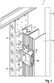
- the Figure 1 shows an exemplary embodiment of a switch cabinet arrangement 1 with a switch cabinet 2 and a power strip 3, which is mounted on a vertical profile 5 of the switch cabinet 2 via a suspension adapter 4.
- the vertical profile 5 is designed here as a 19" installation rail, as is installed in IT racks in the frame of the switch cabinet 2 in order to provide the 19" installation dimension customary in the IT sector.
- the vertical profile 5 is fixed via its opposite longitudinal ends to a horizontal profile of the frame of the switch cabinet 2.
- the vertical profile 5 has a contour 19 within which a power strip can be mounted in a space-saving manner using the switch cabinet arrangement 1 according to the invention.
- the adapter 4 has a first adapter part 6, which is mounted in the contour 19, and a second adapter part 7, which is secured to a rear side 29 via a tongue and groove connection 28.
- the first adapter part 6 further comprises a series interface 23, via which an extension adapter 24 with a complementary interface is attached.
- the extension adapter 24 also comprises, on its side facing the power strips 3, an interface in the form of plug-in receptacles 9, via which the power strips 3 can be plugged into the first adapter part 6 or the extension adapter 24.
- the extension adapter 24 comprises, on its side facing away from the first adapter part 6, a further complementary series interface 25 for the series connection of either a further extension adapter 24 or for the series connection of a first adapter part 6.
- the extension adapter 24 can thus be designed symmetrically in a direction perpendicular to the longitudinal direction of the power strips 3.
- the second adapter parts 7 expand a mushroom head 10 (not visible), via which they are suspended vertically from above into the respective plug receptacle 9 of the first adapter part 6 or the extension adapter 24.
- the plug receptacles 9 can be designed as snap-in receptacles, so that the socket strips 3 are not only held in the plug receptacles 9 due to their own weight, but are also secured against accidental falling out of the plug receptacles.
- the plug receptacles 9 have a stop for the mushroom head 10 at the end in the insertion direction, via which a defined end position of the mushroom head 10 in the plug receptacle 9 is achieved in the vertical downward direction.
- socket strips 3 are shown as U-shaped housings in all figures.
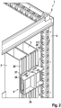
- the Figure 2 shows a modification of the embodiment according to Figure 1 , which differs in particular in that the two socket strips 3 are fixed directly to the frame of the control cabinet 2, i.e. to a vertical profile of the frame 2.
- the extension adapter 24 is basically identical to that in Figure 1 shown extension adapter 24, the first adapter part 6 is designed for mounting on the vertical profile of the frame 2.
- the first adapter part 6 can, for example, have the geometry as shown in Figure 8 , bottom right.
- the first adapter part 6 can in particular have a fastening flange 32, via which the first adapter part 6 can be screwed to the vertical profile via the system perforation of the vertical profile of the control cabinet.
- the Figure 3 shows, in an exploded view, the interaction of a power strip 3 with a first and a second adapter part 6, 7.
- the second adapter part 7 is screwed to the rear of the power strip 3 facing the first adapter part 6 via a detachable connection 8, which in the present case is a screw connection with the aid of a screw bolt 13.
- the power strip 3 On the rear side 29, the power strip 3 further has two longitudinal grooves 28 extending in the longitudinal direction and over the entire length of the socket housing shown, via which a tongue and groove connection is formed in cooperation with corresponding bearing projections on the side of the second adapter part 7 facing the rear side 29.
- the second adapter part can have a mushroom head 10 which extends from the second adapter part 7 via a shaft 12 on a side of the second adapter part facing away from the rear side 29 of the socket strip 3, wherein the mushroom head 10 has a central through-bore via which the screw bolt 13 can be screwed through the mushroom head 10 and the shaft 12 into the rear side 29 of the socket housing 3.
- the first adapter part 6 has, on its front side 31 facing the rear side 29, a plug-in receptacle 9 opposite the socket strip 3 in the longitudinal direction, which plug-in receptacle is designed as a latching receptacle and is open to one of two opposite upper sides 30 of the first adapter part 6 and to a front side 31 of the first adapter part 6 facing the second adapter part 7.
- the plug-in receptacle 9 is further designed with an undercut in order to accommodate the mushroom head 10 (cf. Figure 7 ) in the socket 9.
- the first adapter part 6 further comprises a baying interface 23 on a front side 22 perpendicular to the fastening side 15.
- the baying adapter 24 (cf. Fig. 1 ) with an interface 25 complementary to the series interface 23.
- the arrangement is in accordance with Figure 3 with a view of the fastening side 15 of the first adapter part 6.
- the fastening side 15 is aligned with the vertical profile 5 (cf. Figure 1 ) and has a shaped and/or locking piece 16, which in the present embodiment is composed of a shaped piece 18 and locking projections 21.
- the shaped piece 18 is designed to have a contour 19 (cf. Figure 1 ) of the vertical profile 5 in a complementary manner at least in sections, so that at least in sections a positive engagement of the first adapter part 6 via the shaped piece 18 on the vertical profile 5 can be achieved.
- locking means 21 extend from the shaped piece 18, which are designed to engage in a system perforation 17 (see Figure 1 ) of the vertical profile 5 and to engage behind them, so that a force-locking connection of the first adapter part 6 to the vertical profile 5 can be achieved.
- the Figure 5 shows a non-claimed embodiment in which the first adapter part is designed in the form of keyhole-shaped cutouts in a mounting side 14 of the vertical profile 5. Accordingly, the keyhole-shaped cutouts form plug-in receptacles 9, via which a socket strip 3, which has a second adapter part 7 on its rear side 29, can be hooked directly into the vertical profile 5.
- the Figures 1 to 4 shown embodiments with the in Figure 5 shown embodiment, at least insofar as the second adapter parts 7 shown in the different embodiments can be designed identically. This provides a highly flexible mounting option for the socket strips inside the control cabinet 2.
- the Figure 8 shows various combinations of first adapter parts 6 and extension adapters 24.
- two first adapter parts 6 are connected to each other via an extension adapter 24.
- Both the two first adapter parts 6 and the extension adapter 24 have plug-in receptacles 9, so that the Figure 8
- the arrangement shown top left, comprising two first adapter parts 6 and an extension adapter 24, is designed for the suspended mounting of two socket strips arranged next to one another.
- this arrangement is symmetrical in that, on the one hand, the arrangement comprising two first adapter parts 6 and an extension adapter 24 can be mounted on a vertical profile via either one of the two first adapter parts 6, for example on a left 19" vertical profile in the switch cabinet or on a right vertical profile of the frame of a switch cabinet.
- the arrangement is symmetrical in that the individual components 6, 24 each have a plug-in receptacle 9 on opposite sides, so that the arrangement can be mounted optionally on a left or a right vertical profile even in a position rotated by 180°, and in each case provides the functionality according to the invention.
- the first adapter part 6 is designed to be fixed via its fastening flange 32 to a vertical profile of a switch cabinet frame via its system perforation.
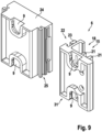
- FIG. 9 shows in particular that an embodiment of the first adapter part 6 can have three functional sides.
- plug-in receptacles 9 are formed, which can be arranged facing a second adapter part.
- the first adapter part 6 has, on its fastening side 15 opposite the front side 31, a shaped piece 18 and locking projections 21 for securing the first adapter part 6 to a vertical profile, for example, to a 19" mounting rail.
- Perpendicular to the front side 31 and the fastening side 25 is the end face 22 of the first adapter part 6, on which the first adapter part 6 has a series interface 23 for the series connection of an extension adapter 24.
- the extension adapter 24 accordingly has a complementary interface 25 facing the end face 22.
Landscapes
- Engineering & Computer Science (AREA)
- Power Engineering (AREA)
- Computer Hardware Design (AREA)
- General Engineering & Computer Science (AREA)
- Microelectronics & Electronic Packaging (AREA)
- Patch Boards (AREA)
- Casings For Electric Apparatus (AREA)
- Connector Housings Or Holding Contact Members (AREA)
- Light Guides In General And Applications Therefor (AREA)
Claims (12)
- Disposition d'armoire de commande (1) avec au moins une armoire de commande (2) et au moins une barre d'alimentation (3), dans laquelle la barre d'alimentation (3) est fixée par l'intermédiaire d'un adaptateur accroché (4) à un profilé vertical (5) à l'intérieur de l'armoire de commande (2), qui comprend une première partie d'adaptateur (6) sur le profilé vertical (5) et une deuxième partie d'adaptateur (7) sur la barre d'alimentation (3), dans laquelle la barre d'alimentation (3) est accrochée, par l'intermédiaire de la deuxième partie d'adaptateur (7), dans la première partie d'adaptateur (6) sur le profilé vertical (5), dans laquelle la première partie d'adaptateur (6) comprend, sur une face de fixation (15), pour le montage de la première partie d'adaptateur (6) sur le profilé vertical (5), au moins une pièce moulée et/ou une pièce d'encliquetage (16), par l'intermédiaire de laquelle la première partie d'adaptateur (6) est fixée, par complémentarité de forme et/ou par force, dans un système de perforations (17) du profilé vertical (5), dans laquelle la première partie d'adaptateur (6) présente une face avant (31) avec un logement d'enfichage (9) pour la deuxième partie d'adaptateur (7),
caractérisée en ce que l'au moins une pièce moulée et/ou d'encliquetage (16) est disposée en face du logement d'enfichage (9). - Disposition d'armoire de commande (1) selon la revendication 1, dans laquelle la deuxième partie d'adaptateur (7) est fixée à la barre d'alimentation (3) par l'intermédiaire d'une liaison amovible (8), de préférence par l'intermédiaire d'une liaison vissée.
- Disposition d'armoire de commande (1) selon la revendication 1 ou 2, dans laquelle le logement d'enfichage (9) est un logement d'encliquetage ou un trou de serrure et la deuxième partie d'adaptateur (7) présente une tête de champignon (10) qui est accrochée dans le logement d'enfichage (9).
- Disposition d'armoire de commande (1) selon la revendication 3, dans laquelle la deuxième partie d'adaptateur (7) présente une face d'appui (11) opposée à la barre d'alimentation (3), par l'intermédiaire de laquelle la deuxième partie d'adaptateur (7) s'appuie contre la première partie d'adaptateur (6) ou contre le profilé vertical (5), dans laquelle la tête de champignon (10) dépasse de la face d'appui (11) avec une tige (12) qui est bloquée dans le logement d'enfichage (9) par l'intermédiaire d'une liaison d'encliquetage.
- Disposition d'armoire de commande (1) selon la revendication 3, dans laquelle la deuxième partie d'adaptateur (7) est fixée à une face arrière de la barre d'alimentation (3) par l'intermédiaire d'une tige vissée (13), dans laquelle la tige vissée (13) s'étend, à partir de la tête de champignon (10), à travers la tête de champignon (10) et de la tige (12), jusqu'à la face arrière de la barre d'alimentation (3).
- Disposition d'armoire de commande (1) selon la revendication 1, dans laquelle la pièce moulée et/ou d'encliquetage (16) comprend une pièce moulée (18) qui s'appuie, par complémentarité de forme, contre un contour (19) d'un profilé vertical (5) d'un châssis (20) ou contre un contour (19) d'un rail profilé, dans laquelle la pièce moulée (18) présente au moins une saillie d'encliquetage (21), par l'intermédiaire de laquelle la pièce moulée et/ou d'encliquetage (16) s'emboîte dans le système de perforations (17) du profilé vertical (5) ou du rail profilé et s'accroche derrière celui-ci.
- Disposition d'armoire de commande (1) selon la revendication 1, dans laquelle la première partie d'adaptateur (6) comprend, au niveau d'une face frontale (22) perpendiculaire à la face de fixation (15), une interface d'alignement (23).
- Disposition d'armoire de commande (1) selon la revendication 7, dans laquelle l'interface d'alignement (23) permet de fixer un adaptateur d'extension (24) avec une interface (25) complémentaire de l'interface d'alignement (23), dans laquelle l'adaptateur d'extension (24) comprend une troisième partie d'adaptateur (26) par l'intermédiaire de laquelle une barre d'alignement (3) supplémentaire est fixée par l'intermédiaire d'une quatrième partie d'adaptateur (27).
- Disposition d'armoire de commande (1) selon la revendication 8, dans laquelle la troisième partie d'adaptateur (26) est identique à la première partie d'adaptateur (6) et la quatrième partie d'adaptateur (27) est identique à la deuxième partie d'adaptateur (7).
- Disposition d'armoire de commande (1) selon la revendication 8, dans laquelle la première partie d'adaptateur (6) et la troisième partie d'adaptateur (26) présentent chacune un logement d'enfichage (9) et de préférence le même logement d'enfichage (9), dans laquelle les deux logements d'enfichage (9) sont disposés sur le même plan.
- Disposition d'armoire de commande (1) selon l'une des revendications précédentes, dans laquelle la deuxième partie d'adaptateur (7) est reliée, par l'intermédiaire d'une liaison par rainure et languette (28) s'étendant dans la direction longitudinale de la barre d'alimentation (3), avec une face arrière (29), opposée aux prises de la barre d'alimentation (3), de la barre d'alimentation (3).
- Disposition d'armoire de commande (1) selon l'une des revendications précédentes, dans laquelle la première partie d'adaptateur (6) présente un logement d'enfichage (9), par exemple un logement d'encliquetage, qui est ouvert vers une face supérieure (30) de la première partie d'adaptateur (6) et vers une face avant (31) de la première partie d'adaptateur (6), orientée vers la deuxième partie d'adaptateur (7), et est réalisé avec une contre-dépouille uniquement dans la direction perpendiculaire à la face avant (31).
Applications Claiming Priority (2)
| Application Number | Priority Date | Filing Date | Title |
|---|---|---|---|
| DE102019104723.4A DE102019104723B4 (de) | 2019-02-25 | 2019-02-25 | Schaltschrankanordnung mit einem Schaltschrank und mindestens einer Steckdosenleiste |
| PCT/DE2020/100097 WO2020173522A1 (fr) | 2019-02-25 | 2020-02-13 | Agencement d'armoire électrique avec une armoire électrique et au moins une barre de prises |
Publications (2)
| Publication Number | Publication Date |
|---|---|
| EP3931924A1 EP3931924A1 (fr) | 2022-01-05 |
| EP3931924B1 true EP3931924B1 (fr) | 2025-04-02 |
Family
ID=69740071
Family Applications (1)
| Application Number | Title | Priority Date | Filing Date |
|---|---|---|---|
| EP20708415.3A Active EP3931924B1 (fr) | 2019-02-25 | 2020-02-13 | Assemblage avec une armoire électrique et au moins une barre multiprise |
Country Status (9)
| Country | Link |
|---|---|
| US (1) | US11689001B2 (fr) |
| EP (1) | EP3931924B1 (fr) |
| CN (1) | CN113474958B (fr) |
| AR (1) | AR118101A1 (fr) |
| DE (1) | DE102019104723B4 (fr) |
| ES (1) | ES3026439T3 (fr) |
| FI (1) | FI3931924T3 (fr) |
| MX (1) | MX2021007991A (fr) |
| WO (1) | WO2020173522A1 (fr) |
Citations (6)
| Publication number | Priority date | Publication date | Assignee | Title |
|---|---|---|---|---|
| US20050101193A1 (en) * | 2003-11-12 | 2005-05-12 | The Wiremold Company, Brooks Electronics Division | Remote display ammeter for power plug or power strip |
| DE102005051941A1 (de) * | 2005-10-29 | 2007-05-10 | Rittal Gmbh & Co. Kg | Befestigungsvorrichtung für Flachteile an Rahmenprofilen von Schaltschränken oder Racks |
| US20080258026A1 (en) * | 2007-04-18 | 2008-10-23 | Leviton Manufacturing Co., Inc. | Equipment rack support bracket for power distribution units |
| US7535696B2 (en) * | 2004-05-21 | 2009-05-19 | Server Technology, Inc. | Method of mounting a power distribution apparatus in a rack |
| US20140070679A1 (en) * | 2012-09-07 | 2014-03-13 | An-Gang Liang | Power distribution unit and server cabinet with the same |
| EP2608645B1 (fr) * | 2011-12-20 | 2015-04-22 | EATON Industries Manufacturing GmbH | Ensemble de montage pour assembler un équipement électronique sur un support |
Family Cites Families (13)
| Publication number | Priority date | Publication date | Assignee | Title |
|---|---|---|---|---|
| CN2481938Y (zh) * | 2001-06-15 | 2002-03-13 | 华为技术有限公司 | 便于移动的导线线卡 |
| DE10359489B4 (de) | 2003-02-27 | 2009-06-04 | Rittal Gmbh & Co. Kg | Elektrifiziereinrichtung für ein Rahmengestell eines Schaltschrankes oder Racks |
| US7360659B1 (en) * | 2003-12-12 | 2008-04-22 | Unisys Corporation | Space-saving mounting fixture for use with an equipment rack |
| DE202004018495U1 (de) | 2004-11-30 | 2006-04-06 | Richter, Jörg | Befestigungsplatte zum Anbringen eines elektrotechnischen Bauteils an einer Schiene eines Schaltschrankrahmens |
| US20070257169A1 (en) * | 2006-04-20 | 2007-11-08 | Brad Taggett | Quick Release Power Strip Bracket assembly |
| TW201206306A (en) * | 2010-07-23 | 2012-02-01 | Hon Hai Prec Ind Co Ltd | Rack |
| CN103869877A (zh) * | 2012-12-12 | 2014-06-18 | 鸿富锦精密工业(深圳)有限公司 | 机柜 |
| DE102014100417B3 (de) * | 2014-01-15 | 2015-04-02 | Rittal Gmbh & Co. Kg | Rahmenprofil für ein Rahmengestell eines Schaltschranks sowie Befestigungsclip für das Rahmenprofil |
| US10030689B2 (en) | 2014-03-12 | 2018-07-24 | Rittal Gmbh & Co. Kg | Mounting system for mounting of equipment in particular electrical appliances |
| KR102418520B1 (ko) | 2015-09-04 | 2022-07-08 | 삼성디스플레이 주식회사 | 표시 장치 |
| AT14807U3 (de) | 2016-02-17 | 2017-04-15 | P Zernig Unternehmensberatung E U | Anschlusssystem |
| DE102017113811A1 (de) | 2017-06-22 | 2018-12-27 | Abb Schweiz Ag | Anordnung für einen Verteilerkasten |
| CN111787725B (zh) * | 2019-04-04 | 2021-08-27 | 鸿富锦精密电子(天津)有限公司 | 止位固定机构及机柜 |
-
2019
- 2019-02-25 DE DE102019104723.4A patent/DE102019104723B4/de active Active
-
2020
- 2020-02-13 ES ES20708415T patent/ES3026439T3/es active Active
- 2020-02-13 EP EP20708415.3A patent/EP3931924B1/fr active Active
- 2020-02-13 MX MX2021007991A patent/MX2021007991A/es unknown
- 2020-02-13 CN CN202080016165.1A patent/CN113474958B/zh active Active
- 2020-02-13 US US17/426,690 patent/US11689001B2/en active Active
- 2020-02-13 WO PCT/DE2020/100097 patent/WO2020173522A1/fr not_active Ceased
- 2020-02-13 FI FIEP20708415.3T patent/FI3931924T3/fi active
- 2020-02-14 AR ARP200100417A patent/AR118101A1/es active IP Right Grant
Patent Citations (6)
| Publication number | Priority date | Publication date | Assignee | Title |
|---|---|---|---|---|
| US20050101193A1 (en) * | 2003-11-12 | 2005-05-12 | The Wiremold Company, Brooks Electronics Division | Remote display ammeter for power plug or power strip |
| US7535696B2 (en) * | 2004-05-21 | 2009-05-19 | Server Technology, Inc. | Method of mounting a power distribution apparatus in a rack |
| DE102005051941A1 (de) * | 2005-10-29 | 2007-05-10 | Rittal Gmbh & Co. Kg | Befestigungsvorrichtung für Flachteile an Rahmenprofilen von Schaltschränken oder Racks |
| US20080258026A1 (en) * | 2007-04-18 | 2008-10-23 | Leviton Manufacturing Co., Inc. | Equipment rack support bracket for power distribution units |
| EP2608645B1 (fr) * | 2011-12-20 | 2015-04-22 | EATON Industries Manufacturing GmbH | Ensemble de montage pour assembler un équipement électronique sur un support |
| US20140070679A1 (en) * | 2012-09-07 | 2014-03-13 | An-Gang Liang | Power distribution unit and server cabinet with the same |
Also Published As
| Publication number | Publication date |
|---|---|
| DE102019104723A1 (de) | 2020-08-27 |
| CN113474958A (zh) | 2021-10-01 |
| CN113474958B (zh) | 2024-10-11 |
| AR118101A1 (es) | 2021-09-15 |
| WO2020173522A1 (fr) | 2020-09-03 |
| US20220109288A1 (en) | 2022-04-07 |
| EP3931924A1 (fr) | 2022-01-05 |
| ES3026439T3 (en) | 2025-06-11 |
| DE102019104723B4 (de) | 2024-01-11 |
| FI3931924T3 (fi) | 2025-06-24 |
| US11689001B2 (en) | 2023-06-27 |
| MX2021007991A (es) | 2021-08-16 |
Similar Documents
| Publication | Publication Date | Title |
|---|---|---|
| DE102015114814B4 (de) | System aus Steckverbinder-Modulrahmen und Adapterelementen sowie modularen Steckverbinder mit einem solchen System | |
| EP3905451A1 (fr) | Module de connecteur enfichable pourvu d'un élément de module | |
| DE102016107565A1 (de) | Anordnung für die berührungssichere Kontaktierung eines Stromsammelschienensystems | |
| EP2171817B1 (fr) | Dispositif pour installer et fixer des unités électriques, en particulier dans une armoire de distribution, ainsi que système de montage comportant un tel dispositif | |
| EP3480898A1 (fr) | Cadre de support modulaire pour connecteur enfichable | |
| EP3954007B1 (fr) | Système de jeu de barres avec au moins une barre retenue dans un boîtier de protection de contact | |
| DE102013114315A1 (de) | Metallisches Schutzleiteranschlusselement und elektrische Reihenklemme | |
| DE102011056463A1 (de) | Gehäuse zum Aufnehmen von Bauteilen, insbesondere von elektronischen Baugruppen, Bauelementen und dergleichen | |
| EP3607624B1 (fr) | Ensemble comprenant un socle et un châssis pour armoire électrique ainsi qu'une rangée d'armoires électriques | |
| EP3931924B1 (fr) | Assemblage avec une armoire électrique et au moins une barre multiprise | |
| EP2760090A1 (fr) | Système de fixation et kit d'intégration pour le montage d'une passerelle de montage dans une armoire de commande | |
| EP3461963B1 (fr) | Système porteur et système d'éléments de connexion permettant la connexion des porteurs | |
| EP2523281B1 (fr) | Caniveau de câbles | |
| DE202013102648U1 (de) | Gehäuse zum Aufnehmen von Bauteilen, insbesondere von elektronischen Baugruppen, Bauelementen und dergleichen | |
| DE102017114129B4 (de) | Montageplattenanordnung für den Innenausbau eines Schaltschranks und ein entsprechender Schaltschrank | |
| DE10135662A1 (de) | Gerätebecherrahmen für Unterfluranwendungen | |
| DE102006029807B4 (de) | Befestigungsvorrichtung mit Schwenkbasis | |
| DE102019009196A1 (de) | Stromsammelschienensystem mit einem eine Verriegelungsanzeige aufweisenden Berührungsschutzgehäuse sowie ein entsprechendes Verfahren | |
| EP2077705B1 (fr) | Support variable destiné au montage sur deux profilés de support verticaux d'un rack et procédé de montage | |
| EP2263292A1 (fr) | Dispositif de décharge de traction | |
| EP1881268A1 (fr) | Dispositif de fixation destiné à la fixation de pièces rapportées | |
| DE102024201958A1 (de) | Elektroinstallationsverteiler, Tragschiene und Montageverfahren | |
| DE202020105837U1 (de) | Schienensystem für die Wandbefestigung eines Schaltschranks und Schaltschrankanordnung mit einem solchen Schienensystem | |
| DE202017101149U1 (de) | Träger für Regalböden oder dgl. | |
| EP0852836B1 (fr) | Element de liaison pour la fixation d'elements porteurs |
Legal Events
| Date | Code | Title | Description |
|---|---|---|---|
| STAA | Information on the status of an ep patent application or granted ep patent |
Free format text: STATUS: UNKNOWN |
|
| STAA | Information on the status of an ep patent application or granted ep patent |
Free format text: STATUS: THE INTERNATIONAL PUBLICATION HAS BEEN MADE |
|
| PUAI | Public reference made under article 153(3) epc to a published international application that has entered the european phase |
Free format text: ORIGINAL CODE: 0009012 |
|
| STAA | Information on the status of an ep patent application or granted ep patent |
Free format text: STATUS: REQUEST FOR EXAMINATION WAS MADE |
|
| 17P | Request for examination filed |
Effective date: 20210618 |
|
| AK | Designated contracting states |
Kind code of ref document: A1 Designated state(s): AL AT BE BG CH CY CZ DE DK EE ES FI FR GB GR HR HU IE IS IT LI LT LU LV MC MK MT NL NO PL PT RO RS SE SI SK SM TR |
|
| DAV | Request for validation of the european patent (deleted) | ||
| DAX | Request for extension of the european patent (deleted) | ||
| STAA | Information on the status of an ep patent application or granted ep patent |
Free format text: STATUS: EXAMINATION IS IN PROGRESS |
|
| RIC1 | Information provided on ipc code assigned before grant |
Ipc: H02B 1/32 20060101ALN20220822BHEP Ipc: H02B 1/30 20060101AFI20220822BHEP |
|
| 17Q | First examination report despatched |
Effective date: 20220916 |
|
| P01 | Opt-out of the competence of the unified patent court (upc) registered |
Effective date: 20230525 |
|
| GRAP | Despatch of communication of intention to grant a patent |
Free format text: ORIGINAL CODE: EPIDOSNIGR1 |
|
| STAA | Information on the status of an ep patent application or granted ep patent |
Free format text: STATUS: GRANT OF PATENT IS INTENDED |
|
| RIC1 | Information provided on ipc code assigned before grant |
Ipc: H02B 1/32 20060101ALN20241010BHEP Ipc: H02B 1/30 20060101AFI20241010BHEP |
|
| RIC1 | Information provided on ipc code assigned before grant |
Ipc: H02B 1/32 20060101ALN20241016BHEP Ipc: H02B 1/30 20060101AFI20241016BHEP |
|
| INTG | Intention to grant announced |
Effective date: 20241029 |
|
| RIC1 | Information provided on ipc code assigned before grant |
Ipc: H02B 1/32 20060101ALN20241018BHEP Ipc: H02B 1/30 20060101AFI20241018BHEP |
|
| GRAS | Grant fee paid |
Free format text: ORIGINAL CODE: EPIDOSNIGR3 |
|
| GRAA | (expected) grant |
Free format text: ORIGINAL CODE: 0009210 |
|
| STAA | Information on the status of an ep patent application or granted ep patent |
Free format text: STATUS: THE PATENT HAS BEEN GRANTED |
|
| AK | Designated contracting states |
Kind code of ref document: B1 Designated state(s): AL AT BE BG CH CY CZ DE DK EE ES FI FR GB GR HR HU IE IS IT LI LT LU LV MC MK MT NL NO PL PT RO RS SE SI SK SM TR |
|
| REG | Reference to a national code |
Ref country code: GB Ref legal event code: FG4D Free format text: NOT ENGLISH |
|
| REG | Reference to a national code |
Ref country code: CH Ref legal event code: EP |
|
| REG | Reference to a national code |
Ref country code: IE Ref legal event code: FG4D Free format text: LANGUAGE OF EP DOCUMENT: GERMAN |
|
| REG | Reference to a national code |
Ref country code: DE Ref legal event code: R096 Ref document number: 502020010743 Country of ref document: DE |
|
| REG | Reference to a national code |
Ref country code: SE Ref legal event code: TRGR |
|
| REG | Reference to a national code |
Ref country code: ES Ref legal event code: FG2A Ref document number: 3026439 Country of ref document: ES Kind code of ref document: T3 Effective date: 20250611 |
|
| REG | Reference to a national code |
Ref country code: FI Ref legal event code: FGE |
|
| REG | Reference to a national code |
Ref country code: NL Ref legal event code: FP |
|
| PG25 | Lapsed in a contracting state [announced via postgrant information from national office to epo] |
Ref country code: PT Free format text: LAPSE BECAUSE OF FAILURE TO SUBMIT A TRANSLATION OF THE DESCRIPTION OR TO PAY THE FEE WITHIN THE PRESCRIBED TIME-LIMIT Effective date: 20250804 |
|
| REG | Reference to a national code |
Ref country code: LT Ref legal event code: MG9D |
|
| PG25 | Lapsed in a contracting state [announced via postgrant information from national office to epo] |
Ref country code: GR Free format text: LAPSE BECAUSE OF FAILURE TO SUBMIT A TRANSLATION OF THE DESCRIPTION OR TO PAY THE FEE WITHIN THE PRESCRIBED TIME-LIMIT Effective date: 20250703 |
|
| PG25 | Lapsed in a contracting state [announced via postgrant information from national office to epo] |
Ref country code: PL Free format text: LAPSE BECAUSE OF FAILURE TO SUBMIT A TRANSLATION OF THE DESCRIPTION OR TO PAY THE FEE WITHIN THE PRESCRIBED TIME-LIMIT Effective date: 20250402 |
|
| PG25 | Lapsed in a contracting state [announced via postgrant information from national office to epo] |
Ref country code: BG Free format text: LAPSE BECAUSE OF FAILURE TO SUBMIT A TRANSLATION OF THE DESCRIPTION OR TO PAY THE FEE WITHIN THE PRESCRIBED TIME-LIMIT Effective date: 20250402 |
|
| PG25 | Lapsed in a contracting state [announced via postgrant information from national office to epo] |
Ref country code: HR Free format text: LAPSE BECAUSE OF FAILURE TO SUBMIT A TRANSLATION OF THE DESCRIPTION OR TO PAY THE FEE WITHIN THE PRESCRIBED TIME-LIMIT Effective date: 20250402 |
|
| PG25 | Lapsed in a contracting state [announced via postgrant information from national office to epo] |
Ref country code: RS Free format text: LAPSE BECAUSE OF FAILURE TO SUBMIT A TRANSLATION OF THE DESCRIPTION OR TO PAY THE FEE WITHIN THE PRESCRIBED TIME-LIMIT Effective date: 20250702 |
|
| PG25 | Lapsed in a contracting state [announced via postgrant information from national office to epo] |
Ref country code: IS Free format text: LAPSE BECAUSE OF FAILURE TO SUBMIT A TRANSLATION OF THE DESCRIPTION OR TO PAY THE FEE WITHIN THE PRESCRIBED TIME-LIMIT Effective date: 20250802 |
|
| PG25 | Lapsed in a contracting state [announced via postgrant information from national office to epo] |
Ref country code: LV Free format text: LAPSE BECAUSE OF FAILURE TO SUBMIT A TRANSLATION OF THE DESCRIPTION OR TO PAY THE FEE WITHIN THE PRESCRIBED TIME-LIMIT Effective date: 20250402 |
|
| REG | Reference to a national code |
Ref country code: DE Ref legal event code: R097 Ref document number: 502020010743 Country of ref document: DE |
|
| PG25 | Lapsed in a contracting state [announced via postgrant information from national office to epo] |
Ref country code: SM Free format text: LAPSE BECAUSE OF FAILURE TO SUBMIT A TRANSLATION OF THE DESCRIPTION OR TO PAY THE FEE WITHIN THE PRESCRIBED TIME-LIMIT Effective date: 20250402 Ref country code: DK Free format text: LAPSE BECAUSE OF FAILURE TO SUBMIT A TRANSLATION OF THE DESCRIPTION OR TO PAY THE FEE WITHIN THE PRESCRIBED TIME-LIMIT Effective date: 20250402 |
|
| PG25 | Lapsed in a contracting state [announced via postgrant information from national office to epo] |
Ref country code: EE Free format text: LAPSE BECAUSE OF FAILURE TO SUBMIT A TRANSLATION OF THE DESCRIPTION OR TO PAY THE FEE WITHIN THE PRESCRIBED TIME-LIMIT Effective date: 20250402 |
|
| PG25 | Lapsed in a contracting state [announced via postgrant information from national office to epo] |
Ref country code: RO Free format text: LAPSE BECAUSE OF FAILURE TO SUBMIT A TRANSLATION OF THE DESCRIPTION OR TO PAY THE FEE WITHIN THE PRESCRIBED TIME-LIMIT Effective date: 20250402 Ref country code: SK Free format text: LAPSE BECAUSE OF FAILURE TO SUBMIT A TRANSLATION OF THE DESCRIPTION OR TO PAY THE FEE WITHIN THE PRESCRIBED TIME-LIMIT Effective date: 20250402 |
|
| PLBE | No opposition filed within time limit |
Free format text: ORIGINAL CODE: 0009261 |
|
| STAA | Information on the status of an ep patent application or granted ep patent |
Free format text: STATUS: NO OPPOSITION FILED WITHIN TIME LIMIT |
|
| REG | Reference to a national code |
Ref country code: CH Ref legal event code: L10 Free format text: ST27 STATUS EVENT CODE: U-0-0-L10-L00 (AS PROVIDED BY THE NATIONAL OFFICE) Effective date: 20260211 |
|
| REG | Reference to a national code |
Ref country code: CH Ref legal event code: U11 Free format text: ST27 STATUS EVENT CODE: U-0-0-U10-U11 (AS PROVIDED BY THE NATIONAL OFFICE) Effective date: 20260301 |
|
| 26N | No opposition filed |
Effective date: 20260105 |
|
| PGFP | Annual fee paid to national office [announced via postgrant information from national office to epo] |
Ref country code: NL Payment date: 20260218 Year of fee payment: 7 |
|
| PGFP | Annual fee paid to national office [announced via postgrant information from national office to epo] |
Ref country code: SE Payment date: 20260218 Year of fee payment: 7 |
|
| PGFP | Annual fee paid to national office [announced via postgrant information from national office to epo] |
Ref country code: GB Payment date: 20260219 Year of fee payment: 7 |
|
| PGFP | Annual fee paid to national office [announced via postgrant information from national office to epo] |
Ref country code: ES Payment date: 20260319 Year of fee payment: 7 |
|
| PGFP | Annual fee paid to national office [announced via postgrant information from national office to epo] |
Ref country code: DE Payment date: 20260217 Year of fee payment: 7 Ref country code: NO Payment date: 20260217 Year of fee payment: 7 |
|
| PGFP | Annual fee paid to national office [announced via postgrant information from national office to epo] |
Ref country code: AT Payment date: 20260216 Year of fee payment: 7 |
|
| PGFP | Annual fee paid to national office [announced via postgrant information from national office to epo] |
Ref country code: BE Payment date: 20260218 Year of fee payment: 7 Ref country code: FI Payment date: 20260217 Year of fee payment: 7 Ref country code: IT Payment date: 20260227 Year of fee payment: 7 |
|
| PGFP | Annual fee paid to national office [announced via postgrant information from national office to epo] |
Ref country code: CH Payment date: 20260301 Year of fee payment: 7 Ref country code: CZ Payment date: 20260130 Year of fee payment: 7 |