EP2077929B1 - Calibrage d'alesage avant et apres traitement a l'aide d'un systeme d'alimentation pour une machine a roder equipee d'un capteur de force d'alimentation - Google Patents
Calibrage d'alesage avant et apres traitement a l'aide d'un systeme d'alimentation pour une machine a roder equipee d'un capteur de force d'alimentation Download PDFInfo
- Publication number
- EP2077929B1 EP2077929B1 EP07811672A EP07811672A EP2077929B1 EP 2077929 B1 EP2077929 B1 EP 2077929B1 EP 07811672 A EP07811672 A EP 07811672A EP 07811672 A EP07811672 A EP 07811672A EP 2077929 B1 EP2077929 B1 EP 2077929B1
- Authority
- EP
- European Patent Office
- Prior art keywords
- honing
- bore
- tool
- feed system
- feed
- Prior art date
- Legal status (The legal status is an assumption and is not a legal conclusion. Google has not performed a legal analysis and makes no representation as to the accuracy of the status listed.)
- Not-in-force
Links
Images


Classifications
-
- B—PERFORMING OPERATIONS; TRANSPORTING
- B24—GRINDING; POLISHING
- B24B—MACHINES, DEVICES, OR PROCESSES FOR GRINDING OR POLISHING; DRESSING OR CONDITIONING OF ABRADING SURFACES; FEEDING OF GRINDING, POLISHING, OR LAPPING AGENTS
- B24B33/00—Honing machines or devices; Accessories therefor
- B24B33/06—Honing machines or devices; Accessories therefor with controlling or gauging equipment
-
- B—PERFORMING OPERATIONS; TRANSPORTING
- B24—GRINDING; POLISHING
- B24B—MACHINES, DEVICES, OR PROCESSES FOR GRINDING OR POLISHING; DRESSING OR CONDITIONING OF ABRADING SURFACES; FEEDING OF GRINDING, POLISHING, OR LAPPING AGENTS
- B24B33/00—Honing machines or devices; Accessories therefor
- B24B33/02—Honing machines or devices; Accessories therefor designed for working internal surfaces of revolution, e.g. of cylindrical or conical shapes
-
- B—PERFORMING OPERATIONS; TRANSPORTING
- B24—GRINDING; POLISHING
- B24B—MACHINES, DEVICES, OR PROCESSES FOR GRINDING OR POLISHING; DRESSING OR CONDITIONING OF ABRADING SURFACES; FEEDING OF GRINDING, POLISHING, OR LAPPING AGENTS
- B24B33/00—Honing machines or devices; Accessories therefor
- B24B33/08—Honing tools
-
- B—PERFORMING OPERATIONS; TRANSPORTING
- B24—GRINDING; POLISHING
- B24B—MACHINES, DEVICES, OR PROCESSES FOR GRINDING OR POLISHING; DRESSING OR CONDITIONING OF ABRADING SURFACES; FEEDING OF GRINDING, POLISHING, OR LAPPING AGENTS
- B24B49/00—Measuring or gauging equipment for controlling the feed movement of the grinding tool or work; Arrangements of indicating or measuring equipment, e.g. for indicating the start of the grinding operation
- B24B49/16—Measuring or gauging equipment for controlling the feed movement of the grinding tool or work; Arrangements of indicating or measuring equipment, e.g. for indicating the start of the grinding operation taking regard of the load
Definitions
- This invention relates generally to gaging of bores, to be honed, and after being honed, and more particularly, to bore gaging using a feed force sensing capability of a feed system of a honing machine, for purposes such as to achieve improved accuracy, and making compensation for predicted tool wear for honing the compensation.
- the type of feed system described in the above-referenced pending patent application, and other feed systems with force sensing capability can be used in conjunction with the honing tool itself to produce reliable pre- and post-processing gaging of the finished bore, or hole, herein interchangeably referred to by the term bore. Furthermore the data gathered and processed by the machine control computer during this step can be used to make accurate compensations for abrasive wear of the honing tool.
- Current bore measuring methods can be generally categorized as post-process methods and in-process methods.
- the in-process methods primarily consist of either a plug gage that tries to enter the bore during the process or an air gage probe, either separate or built into the tool, measuring the bore during the process.
- Post-process gaging can vary in sophistication from manually placing a bore gage in the bore to automated air gage probes that enter the bore and take multiple readings. No known methods exist where the tool itself, lacking any dedicated measuring attachment, is used to measure the size of the finished bore.
- European Patent No. EP 0 575 675 B1 uses a feed force measuring device, for determining a target end point (final encoder position) before the honing process begins.
- This method uses a calibration ring (or sample workpiece) that has been made with a bore size equal to the desired final bore size.
- the honing tool is expanded in the bore of this calibration ring until a certain level of force is measured in the feed force measuring device.
- the last recorded feed force of the last honing cycle is used. When this force is reached with the tool in the calibration ring, the feed system position is recorded as the target position for the next honing cycle.
- EP 0575675 B1 Another observed shortcoming in the disclosure of EP 0575675 B1 , is that no difference between measurements made under static and dynamic conditions is noted or recognized.
- the feed force and position are measured under static conditions, that is with no relative rotation and/or stroking of the tool and workpiece, but, in the workpiece bore, the measurements are made under the dynamic conditions of the honing process, i.e., the honing tool is at least rotating and there may be a relative stroking motion between the tool and the bore.
- the honing tool is at least rotating and there may be a relative stroking motion between the tool and the bore.
- the object of the invention is to provide a method capable of making pre- and post-process measurements of bores of honed workpieces which verify the desired bore size and allow the ability for a machine control system to gather accurate process data for purposes including improving the accuracy of the honing process and compensation for tool wear. This object is achieved by a method comprising the features of claim 1. Preferred ways to carry out the method of the invention are claimed in claims 2 to 8.
- a capability of making measurements of bores of workpieces, both pre-and post-process, that enables verifying bore size before honing, and allows more accurately determining honing parameters for reaching a desired finished bore size, including amount of stock or material to be removed, and accompanying tool wear, and the ability for the machine control system to gather accurate process data, for purposes including improving the accuracy of the honing process, is disclosed.
- the present invention makes all comparative bore measurements, that is, those in both the workpiece bore and the calibration ring or sample workpiece bore, under static conditions.
- the present invention makes tool wear compensations before the workpiece bore is honed, as a function of the amount of stock or material to be removed from the workpiece in the honing operation.
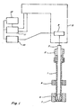
- FIG. 1 is a simplified schematic representation of aspects of a representative honing machine for performing steps of the method of the present invention, including a feed system, a honing tool, and a calibration ring, and showing the honing tool disposed in position in a bore of a representative workpiece to be honed;
- FIG. 2 is a simplified graphical representation of stone wear verses stock removal according to the method of the invention
- FIG. 3 is a simplified schematic representation of aspects of a representative multiple spindle honing machine for performing steps of the method of the present invention, including respective feed systems for the spindles, a honing tool of each of the spindles disposed in bores of workpieces to be honed, and a calibration ring in association with one of the honing tools;
- FIG. 4 is a high level flow diagram illustrating steps of a preferred embodiment of a method of the invention.
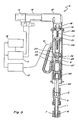
- FIG. 5 is a side view, in partial section, of a representative honing machine spindle with which the invention can be used.
- a honing tool 1 is fixed in the spindle 2 of a honing machine (not shown), which machine can be for instance, any of a variety of machines that provide all the usual required motions for abrasive bore finishing processes (spindle rotation and axial reciprocation of spindle or workpiece).
- the honing tool contains a wedge 3 which is driven axially by a feed system 5 . (Detail of one possible embodiment of the feed system can be seen in FIG.
- the feed force developed in the wedge and feed system is measured by a load cell 9 which transmits an electronic signal back to an amplifier 10 (if required).
- Power and signals run between the amplifier and the honing machine computer control 12 and to a computer controlled motor drive 11 .
- the control of these devices results in signals that precisely control a feed motor or some other driving component of the feed system 5.
- FIG. 4 contains a flow diagram 13 showing steps of one embodiment of the method of the invention, when honing a group of workpieces, the first workpiece must somehow be honed to finished size or close to finished size. This could be done by using any number of conventional initialization techniques. (One such method is described hereinbelow, and in Cloutier, et al, Honing Feed System Having Full Control of Feed Force, Rate, and Position , incorporated herein by reference above.)
- the spindle and stroking motion will stop.
- the feed system will then retract the abrasive stones 6 .
- the feed system will move to once again expand the stones in the same bore of workpiece 7 , this time, though, expansion will be under static conditions, that is, without relative rotational and/or reciprocating movements of the honing tool and workpiece as would be used for actual honing, wherein material or stock is removed from the surface of the bore.
- the expansion will proceed at some predetermined rate until the load cell 9 senses that a predetermined or target level of force has been reached. At that point, the position of the feed system (as determined by an encoder in the feed system) will be recorded, as a target feed system position.
- the predetermined rate of expansion may be one that has been optimized for the accuracy of the position measurement that results when the target level of force is achieved and it is not limited to a single rate or a single forward feeding motion as several techniques may be envisioned for finding the bore in such a manner that a reliable value of position can be measured. (See Cloutier, et al, Honing Feed System Having Full Control of Feed Force, Rate, and Position .)
- the feed system then again retracts the stones and the machine moves the tool up out of the workpiece bore until the abrasive stones are uniformly inside the calibration ring 8 .
- the calibration ring most likely will have a bore that is exactly the desired finished size, although the methods described here will work with any size of ring as long as the difference between the ring's size and the desired finished size is included in the control system calculations. For simplicity the calculations shown here will assume the calibration ring has been made to the exact desired finished size.
- This information can then be used to make a bore size compensation for the honing of the next workpiece. Also this information can be saved and/or output for purposes of Statistical Process Control.
- this measurement step is not a required part of the honing process, it does not need to be performed on every workpiece.
- the operator of the honing machine can select the frequency at which the final bore size measurement will be taken.
- the present invention provides a method to accurately measure both stock removal and stone wear for any given honing cycle or series of honing cycles.
- the process described above constitutes one set of measurements required. Another measurement will also be required. It will be necessary to measure the initial diameter of the workpiece bore. This will occur at the beginning of the cycle after any bore compensation from the previous cycle has been made by the control system.
- the method of measurement is identical to that described above. Under static conditions the feed system expands the stones into the workpiece bore at a predetermined rate until a predetermined force is measured by the load cell. (This process is equivalent to the feature described as Automatic Bore Detection in Cloutier, et al, Honing Feed System Having Full Control of Feed Force, Rate, and Position .)
- At least two groups will need to be measured in order to determine A and B by conventional linear regression techniques. After they have been determined, then the relationship between stone wear and stock removal can be assumed to be known and the above relationship can be used to calculate the expected amount of stone wear before the honing cycle begins. That amount of stone wear can then result in an accurate bore size compensation for anticipated stone wear applied at the beginning of the honing cycle to result in the finished bore size being very close to the target bore size within a minimal range of error. That workpiece-specific bore size compensation will be based on the measured amount of stock removal for that specific bore and calculated from the formula above for w .
- some honing machines use multiple spindles (i.e. tools) in succession to achieve the final finished bore (e.g. a rough honing tool followed by a finer finish honing tool).
- three honing tools 1A, 1B and 1C are used.
- Tools 1A, 1B and 1C are mounted in separate spindles 2A, 2B and 2C of a honing machine which provides all the usual required motions for abrasive bore finishing processes (spindle rotation and axial reciprocation of spindle or workpiece).
- the honing tools contain wedges 3A, 3B and 3C , respectively, driven axially by a feed system 5A, 5B or 5C .
- the feed force developed in the wedge and feed system is measured by a load cell 9A, 9B or 9C which transmits an electronic signal back to an amplifier 10A, 10B or 10C (if required).
- Power and signals run between the amplifiers and the honing machine computer control 12 and to a computer controlled motor drive 11A, 11B or 11C for each tool. It is not necessary to have a calibration ring 8 . for each spindle 2A, 2B and 2C . It is sufficient for only the last spindle 2C to have a calibration ring 8 or some other post process method of accurately measuring the final bore size.
- the workpiece 7C just finished by the last honing tool 1C is measured either by the method described above (using calibration ring 8 ) or by some other post process method of bore gaging. Any bore size compensation that is subsequently determined for that last tool is then made to that last tool.
- the workpiece transfer device (not shown) then indexes presenting the next workpiece to each spindle.
- the workpiece now under the last spindle is the one completed by the previous spindle.
- the tool enters the workpiece and under static conditions the tool is expanded until the abrasive stones contact the bore wall.
- the encoder of the feed system can be read. Following the method previously described, this encoder reading can be mathematically converted to a bore size for that particular workpiece. If that size varies from the target bore size for that previous tool then the appropriate bore size compensation can be made for that previous tool using only the information obtained at the subsequent tool (i.e. no calibration ring will be needed for the previous tool).
- the tool prior to the tool that was just compensated can now be measured and compensated using the same method. This can continue for any number of spindles with the sequence of compensations flowing from last tool to the first tool with each tool being calibrated by means of the bore measurement made from the tool that follows it in the honing operation but has preceded it in this calibration operation.
- FIG. 5 illustrates additional aspects of one possible feed system 5 with which the method of the invention can be used.
- a feed motor 14 of drive 11 is connected to (or is integral with) an encoder 15. If needed to provide the desired characteristics of output torque, output speed, and linear travel per encoder count, a gear reducer 16 may be attached to the shaft of the feed motor 14.
- the gear reducer output shaft is connected to a ball screw assembly 17 by a coupling 18.
- the ball screw assembly 17 resists axial motion by means of ball bearing 19 held in a feed system housing 20.
- the feed system housing 20 may consist of several pieces as required for ease of manufacturing and assembly.
- the ball screw engages a ball nut 21 that is attached to a ball nut carrier 22.
- the ball nut carrier 22 is prevented from rotating by a key 23 that engages a slot 24 in the feed system housing 20. Rotation of the feed motor 14 and subsequently the output shaft of the gear reducer 16 causes the ball screw to rotate, which in turn imparts a linear motion to the ball nut 21 and its carrier 22.
- the key 23, in this embodiment, is integral with a retainer 25 that has a pocket to hold a round disc 26.
- the round disc 26 is attached to one threaded end of load cell 9.
- the pocket has a very small amount of clearance with the round disc 26 for the purpose of allowing the round disc 26 to align itself, with the components below without creating any undesirable stresses on the load cell 9.
- the load cell 9 is fastened to a non-rotating feed rod 27, which is prevented from rotating by a key 28 which also engages the previously mentioned slot 24 in the feed system housing 20.
- the non-rotating feed rod 27 is attached to a tube holding an arrangement of angular contact bearings 29.
- the rotating races of the bearings 29 are attached to a rotating feed rod 30.
- the rotating feed rod 30 is splined or keyed by some means so that it will rotate with the honing machine spindle shaft 2 and yet allows relative axial motion between the spindle shaft 2 and the feed rod 30.
- the spindle shaft 2 holds the honing tool 1 which contains a wedge for expanding abrasive honing elements 6 into the bore of the workpiece 7.
- the wedge is attached to the feed rod 3 and is allowed to move axially with the feed rod 3 while the tool 1 is restrained from axial movement by its connection to the spindle shaft 2. This relative axial motion of the wedge and tool 1 creates the expanding/retracting motion of the abrasive honing elements 6.
- the feed system housing 20 and the spindle shaft 2 are both connected to carriage of a honing machine that strokes them together to generate the axial reciprocation of the honing process.
- the axial force of the wedge to expand the honing elements is developed from the torque of the feed motor and converted to a linear force by the ball screw and nut and then transmitted through the load cell to the feed rod and wedge.
- the load cell therefore always senses the full axial feed force of the honing process.
- the load cell cable 31 is carried through a cable carrier to an amplifier 10 (if required). Power to and signals from the load cell run through this cable and amplifier to a processor based feed control and a servo controller of the feed drive, in connection with motor 14 and encoder 15. The control of these devices result in signals that precisely control the motion of the feed motor.
- feed rate control where the control system keeps the feed motor moving at a constant rate or controlling the rate to some programmed profile that is at least partially a function of feed position.
- force control where the control system keeps the feed motor moving in a manner such that the feed force is held constant or follows some programmed profile that is at least partially a function of feed position.
- Computer control also allows for these two basic methods to be mixed within a honing cycle, e.g. honing at a controlled rate until some condition is met then honing at controlled force until the bore is at final size. Furthermore the computer control allows for a high degree of flexibility in feed control programming. Parameters such as feed rate, feed force, spindle torque, time, number of reciprocation strokes, workpiece temperature, and others can be used in real-time control logic that adapts the controlled feed parameter or even changes the feed control method in a simple or complex programmed manner.
Landscapes
- Engineering & Computer Science (AREA)
- Mechanical Engineering (AREA)
- Physics & Mathematics (AREA)
- Geometry (AREA)
- Finish Polishing, Edge Sharpening, And Grinding By Specific Grinding Devices (AREA)
- Constituent Portions Of Griding Lathes, Driving, Sensing And Control (AREA)
Claims (8)
- Procédé de détermination d'une taille d'un alésage d'une pièce (7) rodée en utilisant un outil de rodage assemblé sur un système d'alimentation (5) de machine à roder apte à mesurer des forces d'alimentation exercées contre l'outil et des positions du système d'alimentation (5) représentatives de positions d'alimentation de l'outil, le procédé étant caractérisé en ce qu'il comprend les étapes de :extension de l'outil (1) à l'intérieur de l'alésage de la pièce (7), sous des conditions statiques, jusqu'à ce qu'une force d'alimentation prédéterminée soit atteinte, et mesure de la position du système d'alimentation (5) ;positionnement de l'outil (1) dans un alésage de taille connue et extension de l'outil (1), sous des conditions statiques, jusqu'à ce que la force d'alimentation prédéterminée soit atteinte, et mesure de la position du système d'alimentation (5) ;détermination d'une valeur représentative de la taille de l'alésage de la pièce (7), comme une fonction de la position mesurée du système d'alimentation (5) pour l'outil (1) dans l'alésage de taille connue, et de la position mesurée du système d'alimentation (5) pour l'outil (1) dans l'alésage de la pièce (7).
- Procédé selon la revendication 1, comprenant des étapes antérieures au rodage de l'alésage de la pièce (7), de :détermination d'une valeur représentative d'une usure prédite de pierre pour roder l'alésage de la pièce (7) ;détermination d'une position cible du système d'alimentation (5) pour roder l'alésage de la pièce (7) à une taille cible, comme une fonction de la taille cible et de la valeur représentative d'une usure prédite de pierre ; etrodage de l'alésage de la pièce (7) jusqu'à ce que la position cible du système d'alimentation (5) soit atteinte.
- Procédé selon la revendication 2, dans lequel la valeur représentative d'une usure prédite de pierre est déterminée comme une fonction d'une quantité de matière devant être enlevée par le rodage de l'alésage jusqu'à la position cible du système d'alimentation (5).
- Procédé selon la revendication 3, dans lequel la valeur représentative d'une usure prédite de pierre est déterminée au moins en partie à partir de mesures d'usure de pierre pour au moins une pièce (7) précédemment rodée.
- Procédé selon la revendication 1, dans lequel les étapes d'extension de l'outil (1) comprennent l'extension de l'outil (1) à une vitesse prédéterminée.
- Procédé selon la revendication 1, comprenant une étape additionnelle de détermination d'une valeur de compensation de système d'alimentation (5) comme une fonction de la position mesurée du système d'alimentation (5) pour l'outil (1) dans l'alésage de taille connue, et de la position mesurée du système d'alimentation (5) pour l'outil (1) dans l'alésage de la pièce (7).
- Procédé selon la revendication 6, comprenant une étape supplémentaire de détermination d'une position cible du système d'alimentation (5) comme une fonction de la valeur de compensation de système d'alimentation (5) et d'une valeur représentative d'une usure prédite de pierre pour une étape subséquente de rodage.
- Procédé selon la revendication 6, comprenant une étape additionnelle d'utilisation de la valeur de compensation de système d'alimentation (5) pour déterminer une position cible du système d'alimentation (5) pour roder l'alésage en utilisant un autre outil de rodage (1).
Applications Claiming Priority (2)
| Application Number | Priority Date | Filing Date | Title |
|---|---|---|---|
| US84232106P | 2006-09-05 | 2006-09-05 | |
| PCT/US2007/019344 WO2008030463A2 (fr) | 2006-09-05 | 2007-09-05 | Calibrage d'alésage avant et après traitement à l'aide d'un système d'alimentation pour une machine à roder équipée d'un capteur de force d'alimentation |
Publications (3)
| Publication Number | Publication Date |
|---|---|
| EP2077929A2 EP2077929A2 (fr) | 2009-07-15 |
| EP2077929A4 EP2077929A4 (fr) | 2011-01-12 |
| EP2077929B1 true EP2077929B1 (fr) | 2012-03-07 |
Family
ID=39157806
Family Applications (1)
| Application Number | Title | Priority Date | Filing Date |
|---|---|---|---|
| EP07811672A Not-in-force EP2077929B1 (fr) | 2006-09-05 | 2007-09-05 | Calibrage d'alesage avant et apres traitement a l'aide d'un systeme d'alimentation pour une machine a roder equipee d'un capteur de force d'alimentation |
Country Status (11)
| Country | Link |
|---|---|
| US (1) | US8096853B2 (fr) |
| EP (1) | EP2077929B1 (fr) |
| JP (1) | JP5101617B2 (fr) |
| KR (1) | KR20090051773A (fr) |
| CN (1) | CN101528417B (fr) |
| AT (1) | ATE548158T1 (fr) |
| BR (1) | BRPI0716168B1 (fr) |
| CA (1) | CA2662155C (fr) |
| ES (1) | ES2383616T3 (fr) |
| MX (1) | MX2009002534A (fr) |
| WO (1) | WO2008030463A2 (fr) |
Families Citing this family (9)
| Publication number | Priority date | Publication date | Assignee | Title |
|---|---|---|---|---|
| US8277280B2 (en) * | 2004-09-07 | 2012-10-02 | Sunnen Products Company | Honing feed system and method employing rapid tool advancement and feed force signal conditioning |
| JP4588014B2 (ja) * | 2006-12-08 | 2010-11-24 | 日立Geニュークリア・エナジー株式会社 | 燃料交換機 |
| PL2432612T3 (pl) * | 2009-05-22 | 2017-07-31 | Sunnen Products Company | Zautomatyzowany proces wykańczania otworów |
| DE102013220507B4 (de) * | 2013-10-11 | 2015-11-05 | Gehring Technologies Gmbh | Vorrichtung und Verfahren zur Erzeugung einer nicht zylindrischen Innenfläche einer Bohrung |
| SE538554C2 (en) * | 2014-12-05 | 2016-09-20 | Applied Nano Surfaces Sweden Ab | Mechanochemical conditioning tool |
| CN105081951B (zh) * | 2015-09-08 | 2018-11-30 | 重庆维庆液压机械有限公司 | 立式珩磨机标尺结构 |
| JP7271983B2 (ja) * | 2019-02-08 | 2023-05-12 | 株式会社ジェイテクト | 熱変位量推定装置および研削盤 |
| CN110253417A (zh) * | 2019-07-05 | 2019-09-20 | 宁夏中卫大河精工机械有限责任公司 | 珩磨加工中心 |
| CN119734166B (zh) * | 2025-03-06 | 2025-04-25 | 佛山市巴赛尔机电有限公司 | 一种磨边机磨轮磨损量自动补偿装置 |
Family Cites Families (11)
| Publication number | Priority date | Publication date | Assignee | Title |
|---|---|---|---|---|
| JPS5973271A (ja) * | 1982-10-16 | 1984-04-25 | Asia Giken Kogyo Kk | サ−ボモ−タ又はパルスモ−タによるホ−ニングマシンの砥石の拡張、収縮、摩耗自動補正方法 |
| US4528776A (en) * | 1983-06-24 | 1985-07-16 | Barnes Drill Co. | Honing machine with stonewear compensator |
| DE3421193A1 (de) * | 1984-06-07 | 1985-12-12 | Maschinenfabrik Gehring Gmbh & Co Kg, 7302 Ostfildern | Verfahren zum zustellen eines honwerkzeuges und vorrichtung zum ausfuehren des verfahrens |
| JPS6487149A (en) * | 1987-09-22 | 1989-03-31 | Toshiba Machine Co Ltd | Grinding amount correcting system for numerical control machine tool |
| DE4024778A1 (de) * | 1990-08-04 | 1992-02-06 | Nagel Masch Werkzeug | Hon-messwerkzeug |
| EP0575657B2 (fr) | 1992-06-26 | 2007-03-21 | Maschinenfabrik Gehring GmbH & Co. | Méthode et machine pour l'usinage au fouesse du perçages dans des pièces à usiner |
| JP2609989B2 (ja) * | 1993-07-29 | 1997-05-14 | 株式会社日進製作所 | ホーニング治具および自動ホーニングシステム |
| JP3766134B2 (ja) * | 1996-03-22 | 2006-04-12 | 日産自動車株式会社 | ホーニング加工の内径補正方法および同補正装置 |
| JP3405060B2 (ja) * | 1996-05-14 | 2003-05-12 | 日産自動車株式会社 | ホーニング加工方法及び同方法に使用する制御装置 |
| JP2002307264A (ja) * | 2001-04-10 | 2002-10-23 | Nisshin Seisakusho:Kk | 自動機械加工システムの加工セルおよび自動ホーニングシステム |
| WO2006029180A1 (fr) * | 2004-09-07 | 2006-03-16 | Sunnen Products Company | Systeme d'alimentation pour une machine a roder les cylindres disposant d'un controle complet de la force, de la vitesse et de la position d'avance et procede correspondant |
-
2007
- 2007-09-05 BR BRPI0716168-9A patent/BRPI0716168B1/pt not_active IP Right Cessation
- 2007-09-05 CN CN2007800389944A patent/CN101528417B/zh not_active Expired - Fee Related
- 2007-09-05 EP EP07811672A patent/EP2077929B1/fr not_active Not-in-force
- 2007-09-05 CA CA2662155A patent/CA2662155C/fr not_active Expired - Fee Related
- 2007-09-05 US US12/439,978 patent/US8096853B2/en active Active
- 2007-09-05 JP JP2009526761A patent/JP5101617B2/ja not_active Expired - Fee Related
- 2007-09-05 ES ES07811672T patent/ES2383616T3/es active Active
- 2007-09-05 AT AT07811672T patent/ATE548158T1/de active
- 2007-09-05 MX MX2009002534A patent/MX2009002534A/es active IP Right Grant
- 2007-09-05 KR KR1020097006809A patent/KR20090051773A/ko not_active Ceased
- 2007-09-05 WO PCT/US2007/019344 patent/WO2008030463A2/fr not_active Ceased
Also Published As
| Publication number | Publication date |
|---|---|
| BRPI0716168B1 (pt) | 2018-07-03 |
| JP5101617B2 (ja) | 2012-12-19 |
| KR20090051773A (ko) | 2009-05-22 |
| ATE548158T1 (de) | 2012-03-15 |
| EP2077929A2 (fr) | 2009-07-15 |
| WO2008030463A2 (fr) | 2008-03-13 |
| US8096853B2 (en) | 2012-01-17 |
| BRPI0716168A2 (pt) | 2013-09-24 |
| JP2010502457A (ja) | 2010-01-28 |
| CA2662155C (fr) | 2014-05-13 |
| WO2008030463A3 (fr) | 2008-11-06 |
| CN101528417A (zh) | 2009-09-09 |
| CA2662155A1 (fr) | 2008-03-13 |
| EP2077929A4 (fr) | 2011-01-12 |
| MX2009002534A (es) | 2009-06-01 |
| US20100210181A1 (en) | 2010-08-19 |
| CN101528417B (zh) | 2011-02-09 |
| ES2383616T3 (es) | 2012-06-22 |
Similar Documents
| Publication | Publication Date | Title |
|---|---|---|
| EP2077929B1 (fr) | Calibrage d'alesage avant et apres traitement a l'aide d'un systeme d'alimentation pour une machine a roder equipee d'un capteur de force d'alimentation | |
| EP1787209B1 (fr) | Systeme d'alimentation pour une machine a roder les cylindres disposant d'un controle complet de la force, de la vitesse et de la position d'avance et procede correspondant | |
| Schajer et al. | Hole-drilling and ring core methods | |
| US8277280B2 (en) | Honing feed system and method employing rapid tool advancement and feed force signal conditioning | |
| US8162722B2 (en) | Grindstone contact sensing method and its device, and honing method and honing machine | |
| CN104029126B (zh) | 用于确认修整工具的构形偏离的方法及相应装备的磨削机 | |
| EP2412477A2 (fr) | Procédé de broyage et meuleuse | |
| CZ200577A3 (cs) | Způsob a zařízení pro vyrovnání mezer mezi zuby obrobku a předem vytvořenými zuby | |
| US9987696B2 (en) | Automated bore finishing process | |
| CN112775731A (zh) | 磨削系统 | |
| EP1766482B1 (fr) | Procede et appareil permettant de commander l'usinage de pieces mecaniques | |
| EP0895615B1 (fr) | Procedes et dispositif pour meuler des zones cylindriques concentriques sur des pieces a travailler | |
| CN114799363A (zh) | 磨齿机及用于齿轮加工的分度补偿方法 | |
| CN1807020B (zh) | 校准方法和使用这种方法的腐蚀和磨削机床 | |
| JP4940904B2 (ja) | かつぎ量計測装置 | |
| JP7840194B2 (ja) | ボールねじの有効径測定方法及び該方法を用いるねじ研削装置 | |
| JP2003311592A (ja) | 研削量予測によるロール研削方法 | |
| CN119141447A (zh) | 一种轴承磨床上主动量仪的在线自动校准方法 |
Legal Events
| Date | Code | Title | Description |
|---|---|---|---|
| PUAI | Public reference made under article 153(3) epc to a published international application that has entered the european phase |
Free format text: ORIGINAL CODE: 0009012 |
|
| 17P | Request for examination filed |
Effective date: 20090401 |
|
| AK | Designated contracting states |
Kind code of ref document: A2 Designated state(s): AT BE BG CH CY CZ DE DK EE ES FI FR GB GR HU IE IS IT LI LT LU LV MC MT NL PL PT RO SE SI SK TR |
|
| RIN1 | Information on inventor provided before grant (corrected) |
Inventor name: MOEHN, DAVID M. Inventor name: CLOUTIER, DANIEL, R. Inventor name: HOTH, TIMOTHY, P. |
|
| DAX | Request for extension of the european patent (deleted) | ||
| A4 | Supplementary search report drawn up and despatched |
Effective date: 20101210 |
|
| GRAP | Despatch of communication of intention to grant a patent |
Free format text: ORIGINAL CODE: EPIDOSNIGR1 |
|
| GRAS | Grant fee paid |
Free format text: ORIGINAL CODE: EPIDOSNIGR3 |
|
| GRAA | (expected) grant |
Free format text: ORIGINAL CODE: 0009210 |
|
| AK | Designated contracting states |
Kind code of ref document: B1 Designated state(s): AT BE BG CH CY CZ DE DK EE ES FI FR GB GR HU IE IS IT LI LT LU LV MC MT NL PL PT RO SE SI SK TR |
|
| REG | Reference to a national code |
Ref country code: GB Ref legal event code: FG4D |
|
| REG | Reference to a national code |
Ref country code: AT Ref legal event code: REF Ref document number: 548158 Country of ref document: AT Kind code of ref document: T Effective date: 20120315 Ref country code: CH Ref legal event code: EP |
|
| REG | Reference to a national code |
Ref country code: IE Ref legal event code: FG4D |
|
| REG | Reference to a national code |
Ref country code: SE Ref legal event code: TRGR |
|
| REG | Reference to a national code |
Ref country code: DE Ref legal event code: R096 Ref document number: 602007021201 Country of ref document: DE Effective date: 20120503 |
|
| REG | Reference to a national code |
Ref country code: ES Ref legal event code: FG2A Ref document number: 2383616 Country of ref document: ES Kind code of ref document: T3 Effective date: 20120622 |
|
| REG | Reference to a national code |
Ref country code: NL Ref legal event code: VDEP Effective date: 20120307 |
|
| PG25 | Lapsed in a contracting state [announced via postgrant information from national office to epo] |
Ref country code: LT Free format text: LAPSE BECAUSE OF FAILURE TO SUBMIT A TRANSLATION OF THE DESCRIPTION OR TO PAY THE FEE WITHIN THE PRESCRIBED TIME-LIMIT Effective date: 20120307 Ref country code: NL Free format text: LAPSE BECAUSE OF FAILURE TO SUBMIT A TRANSLATION OF THE DESCRIPTION OR TO PAY THE FEE WITHIN THE PRESCRIBED TIME-LIMIT Effective date: 20120307 |
|
| LTIE | Lt: invalidation of european patent or patent extension |
Effective date: 20120307 |
|
| PG25 | Lapsed in a contracting state [announced via postgrant information from national office to epo] |
Ref country code: LV Free format text: LAPSE BECAUSE OF FAILURE TO SUBMIT A TRANSLATION OF THE DESCRIPTION OR TO PAY THE FEE WITHIN THE PRESCRIBED TIME-LIMIT Effective date: 20120307 Ref country code: GR Free format text: LAPSE BECAUSE OF FAILURE TO SUBMIT A TRANSLATION OF THE DESCRIPTION OR TO PAY THE FEE WITHIN THE PRESCRIBED TIME-LIMIT Effective date: 20120608 Ref country code: FI Free format text: LAPSE BECAUSE OF FAILURE TO SUBMIT A TRANSLATION OF THE DESCRIPTION OR TO PAY THE FEE WITHIN THE PRESCRIBED TIME-LIMIT Effective date: 20120307 |
|
| REG | Reference to a national code |
Ref country code: AT Ref legal event code: MK05 Ref document number: 548158 Country of ref document: AT Kind code of ref document: T Effective date: 20120307 |
|
| PG25 | Lapsed in a contracting state [announced via postgrant information from national office to epo] |
Ref country code: CY Free format text: LAPSE BECAUSE OF FAILURE TO SUBMIT A TRANSLATION OF THE DESCRIPTION OR TO PAY THE FEE WITHIN THE PRESCRIBED TIME-LIMIT Effective date: 20120307 |
|
| PG25 | Lapsed in a contracting state [announced via postgrant information from national office to epo] |
Ref country code: IS Free format text: LAPSE BECAUSE OF FAILURE TO SUBMIT A TRANSLATION OF THE DESCRIPTION OR TO PAY THE FEE WITHIN THE PRESCRIBED TIME-LIMIT Effective date: 20120707 Ref country code: PL Free format text: LAPSE BECAUSE OF FAILURE TO SUBMIT A TRANSLATION OF THE DESCRIPTION OR TO PAY THE FEE WITHIN THE PRESCRIBED TIME-LIMIT Effective date: 20120307 Ref country code: RO Free format text: LAPSE BECAUSE OF FAILURE TO SUBMIT A TRANSLATION OF THE DESCRIPTION OR TO PAY THE FEE WITHIN THE PRESCRIBED TIME-LIMIT Effective date: 20120307 Ref country code: SI Free format text: LAPSE BECAUSE OF FAILURE TO SUBMIT A TRANSLATION OF THE DESCRIPTION OR TO PAY THE FEE WITHIN THE PRESCRIBED TIME-LIMIT Effective date: 20120307 Ref country code: BE Free format text: LAPSE BECAUSE OF FAILURE TO SUBMIT A TRANSLATION OF THE DESCRIPTION OR TO PAY THE FEE WITHIN THE PRESCRIBED TIME-LIMIT Effective date: 20120307 Ref country code: CZ Free format text: LAPSE BECAUSE OF FAILURE TO SUBMIT A TRANSLATION OF THE DESCRIPTION OR TO PAY THE FEE WITHIN THE PRESCRIBED TIME-LIMIT Effective date: 20120307 Ref country code: EE Free format text: LAPSE BECAUSE OF FAILURE TO SUBMIT A TRANSLATION OF THE DESCRIPTION OR TO PAY THE FEE WITHIN THE PRESCRIBED TIME-LIMIT Effective date: 20120307 |
|
| PG25 | Lapsed in a contracting state [announced via postgrant information from national office to epo] |
Ref country code: PT Free format text: LAPSE BECAUSE OF FAILURE TO SUBMIT A TRANSLATION OF THE DESCRIPTION OR TO PAY THE FEE WITHIN THE PRESCRIBED TIME-LIMIT Effective date: 20120709 Ref country code: SK Free format text: LAPSE BECAUSE OF FAILURE TO SUBMIT A TRANSLATION OF THE DESCRIPTION OR TO PAY THE FEE WITHIN THE PRESCRIBED TIME-LIMIT Effective date: 20120307 |
|
| PLBE | No opposition filed within time limit |
Free format text: ORIGINAL CODE: 0009261 |
|
| STAA | Information on the status of an ep patent application or granted ep patent |
Free format text: STATUS: NO OPPOSITION FILED WITHIN TIME LIMIT |
|
| PG25 | Lapsed in a contracting state [announced via postgrant information from national office to epo] |
Ref country code: AT Free format text: LAPSE BECAUSE OF FAILURE TO SUBMIT A TRANSLATION OF THE DESCRIPTION OR TO PAY THE FEE WITHIN THE PRESCRIBED TIME-LIMIT Effective date: 20120307 Ref country code: DK Free format text: LAPSE BECAUSE OF FAILURE TO SUBMIT A TRANSLATION OF THE DESCRIPTION OR TO PAY THE FEE WITHIN THE PRESCRIBED TIME-LIMIT Effective date: 20120307 |
|
| 26N | No opposition filed |
Effective date: 20121210 |
|
| REG | Reference to a national code |
Ref country code: DE Ref legal event code: R097 Ref document number: 602007021201 Country of ref document: DE Effective date: 20121210 |
|
| PG25 | Lapsed in a contracting state [announced via postgrant information from national office to epo] |
Ref country code: MC Free format text: LAPSE BECAUSE OF NON-PAYMENT OF DUE FEES Effective date: 20120930 |
|
| REG | Reference to a national code |
Ref country code: CH Ref legal event code: PL |
|
| REG | Reference to a national code |
Ref country code: IE Ref legal event code: MM4A |
|
| PG25 | Lapsed in a contracting state [announced via postgrant information from national office to epo] |
Ref country code: IE Free format text: LAPSE BECAUSE OF NON-PAYMENT OF DUE FEES Effective date: 20120905 Ref country code: CH Free format text: LAPSE BECAUSE OF NON-PAYMENT OF DUE FEES Effective date: 20120930 Ref country code: BG Free format text: LAPSE BECAUSE OF FAILURE TO SUBMIT A TRANSLATION OF THE DESCRIPTION OR TO PAY THE FEE WITHIN THE PRESCRIBED TIME-LIMIT Effective date: 20120607 Ref country code: LI Free format text: LAPSE BECAUSE OF NON-PAYMENT OF DUE FEES Effective date: 20120930 |
|
| PG25 | Lapsed in a contracting state [announced via postgrant information from national office to epo] |
Ref country code: MT Free format text: LAPSE BECAUSE OF FAILURE TO SUBMIT A TRANSLATION OF THE DESCRIPTION OR TO PAY THE FEE WITHIN THE PRESCRIBED TIME-LIMIT Effective date: 20120307 |
|
| PG25 | Lapsed in a contracting state [announced via postgrant information from national office to epo] |
Ref country code: TR Free format text: LAPSE BECAUSE OF FAILURE TO SUBMIT A TRANSLATION OF THE DESCRIPTION OR TO PAY THE FEE WITHIN THE PRESCRIBED TIME-LIMIT Effective date: 20120307 |
|
| PG25 | Lapsed in a contracting state [announced via postgrant information from national office to epo] |
Ref country code: LU Free format text: LAPSE BECAUSE OF NON-PAYMENT OF DUE FEES Effective date: 20120905 |
|
| PG25 | Lapsed in a contracting state [announced via postgrant information from national office to epo] |
Ref country code: HU Free format text: LAPSE BECAUSE OF FAILURE TO SUBMIT A TRANSLATION OF THE DESCRIPTION OR TO PAY THE FEE WITHIN THE PRESCRIBED TIME-LIMIT Effective date: 20070905 |
|
| REG | Reference to a national code |
Ref country code: FR Ref legal event code: PLFP Year of fee payment: 10 |
|
| REG | Reference to a national code |
Ref country code: FR Ref legal event code: PLFP Year of fee payment: 11 |
|
| REG | Reference to a national code |
Ref country code: FR Ref legal event code: PLFP Year of fee payment: 12 |
|
| PGFP | Annual fee paid to national office [announced via postgrant information from national office to epo] |
Ref country code: IT Payment date: 20210930 Year of fee payment: 15 Ref country code: FR Payment date: 20210924 Year of fee payment: 15 |
|
| PGFP | Annual fee paid to national office [announced via postgrant information from national office to epo] |
Ref country code: GB Payment date: 20210924 Year of fee payment: 15 Ref country code: DE Payment date: 20210929 Year of fee payment: 15 Ref country code: SE Payment date: 20210924 Year of fee payment: 15 |
|
| PGFP | Annual fee paid to national office [announced via postgrant information from national office to epo] |
Ref country code: ES Payment date: 20211001 Year of fee payment: 15 |
|
| REG | Reference to a national code |
Ref country code: DE Ref legal event code: R119 Ref document number: 602007021201 Country of ref document: DE |
|
| REG | Reference to a national code |
Ref country code: SE Ref legal event code: EUG |
|
| GBPC | Gb: european patent ceased through non-payment of renewal fee |
Effective date: 20220905 |
|
| PG25 | Lapsed in a contracting state [announced via postgrant information from national office to epo] |
Ref country code: FR Free format text: LAPSE BECAUSE OF NON-PAYMENT OF DUE FEES Effective date: 20220930 Ref country code: DE Free format text: LAPSE BECAUSE OF NON-PAYMENT OF DUE FEES Effective date: 20230401 |
|
| PG25 | Lapsed in a contracting state [announced via postgrant information from national office to epo] |
Ref country code: SE Free format text: LAPSE BECAUSE OF NON-PAYMENT OF DUE FEES Effective date: 20220906 |
|
| REG | Reference to a national code |
Ref country code: ES Ref legal event code: FD2A Effective date: 20231027 |
|
| PG25 | Lapsed in a contracting state [announced via postgrant information from national office to epo] |
Ref country code: IT Free format text: LAPSE BECAUSE OF NON-PAYMENT OF DUE FEES Effective date: 20220905 Ref country code: GB Free format text: LAPSE BECAUSE OF NON-PAYMENT OF DUE FEES Effective date: 20220905 |
|
| PG25 | Lapsed in a contracting state [announced via postgrant information from national office to epo] |
Ref country code: ES Free format text: LAPSE BECAUSE OF NON-PAYMENT OF DUE FEES Effective date: 20220906 |
|
| PG25 | Lapsed in a contracting state [announced via postgrant information from national office to epo] |
Ref country code: ES Free format text: LAPSE BECAUSE OF NON-PAYMENT OF DUE FEES Effective date: 20220906 |