EP2078831A2 - Gaine de culbuteur à surface traitée - Google Patents
Gaine de culbuteur à surface traitée Download PDFInfo
- Publication number
- EP2078831A2 EP2078831A2 EP09150266A EP09150266A EP2078831A2 EP 2078831 A2 EP2078831 A2 EP 2078831A2 EP 09150266 A EP09150266 A EP 09150266A EP 09150266 A EP09150266 A EP 09150266A EP 2078831 A2 EP2078831 A2 EP 2078831A2
- Authority
- EP
- European Patent Office
- Prior art keywords
- shaft
- bearing surface
- rocker arm
- core portion
- carbon
- Prior art date
- Legal status (The legal status is an assumption and is not a legal conclusion. Google has not performed a legal analysis and makes no representation as to the accuracy of the status listed.)
- Withdrawn
Links
Images


Classifications
-
- F—MECHANICAL ENGINEERING; LIGHTING; HEATING; WEAPONS; BLASTING
- F01—MACHINES OR ENGINES IN GENERAL; ENGINE PLANTS IN GENERAL; STEAM ENGINES
- F01L—CYCLICALLY OPERATING VALVES FOR MACHINES OR ENGINES
- F01L1/00—Valve-gear or valve arrangements, e.g. lift-valve gear
- F01L1/02—Valve drive
- F01L1/04—Valve drive by means of cams, camshafts, cam discs, eccentrics or the like
- F01L1/047—Camshafts
- F01L1/053—Camshafts overhead type
-
- F—MECHANICAL ENGINEERING; LIGHTING; HEATING; WEAPONS; BLASTING
- F01—MACHINES OR ENGINES IN GENERAL; ENGINE PLANTS IN GENERAL; STEAM ENGINES
- F01L—CYCLICALLY OPERATING VALVES FOR MACHINES OR ENGINES
- F01L1/00—Valve-gear or valve arrangements, e.g. lift-valve gear
- F01L1/12—Transmitting gear between valve drive and valve
- F01L1/18—Rocking arms or levers
-
- F—MECHANICAL ENGINEERING; LIGHTING; HEATING; WEAPONS; BLASTING
- F01—MACHINES OR ENGINES IN GENERAL; ENGINE PLANTS IN GENERAL; STEAM ENGINES
- F01L—CYCLICALLY OPERATING VALVES FOR MACHINES OR ENGINES
- F01L2301/00—Using particular materials
-
- F—MECHANICAL ENGINEERING; LIGHTING; HEATING; WEAPONS; BLASTING
- F01—MACHINES OR ENGINES IN GENERAL; ENGINE PLANTS IN GENERAL; STEAM ENGINES
- F01L—CYCLICALLY OPERATING VALVES FOR MACHINES OR ENGINES
- F01L2303/00—Manufacturing of components used in valve arrangements
Definitions
- the present invention is generally directed to a surface treated rocker arm shaft for an internal combustion engine and is more specifically directed to a surface hardened rocker arm shaft having a case hardened and/or a highly polished surface that is capable of improved wear resistance and deterrence of crack initiation and propagation.
- Internal combustion engines such as multi-cylinder diesel engines, typically include a crankshaft, a camshaft and a rocker arm shaft.
- the crankshaft is connected with a plurality of piston rods, which in turn are connected with a plurality of corresponding pistons. Reciprocating movement of the pistons within corresponding combustion cylinders causes rotation of the crankshaft.
- the crankshaft is typically interconnected with the camshaft via a gear set and thereby rotatably drives the camshaft during operation.
- the camshaft includes a plurality of cams, with each cam being associated with an inlet valve, and an exhaust valve or a fuel injector valve.
- the rocker arm shaft carries a plurality of rocker arms, with each rocker arm having a roller follower that engages a corresponding cam on the camshaft. Rotation of the camshaft causes oscillatory pivotal movement of the rocker arms around the rocker arm shaft.
- the rocker arm shaft is subject to cyclic bending moments as a result of forces applied thereto by the roller follower and cam.
- rocker arm shafts are manufactured from a high strength through hardened steel such as AISI E52100. Through hardening of the steel imparts a high hardness throughout the entire shaft. The expense of some through hardened steels make them impractical for use as rocker arm shafts in typical internal combustion engine.
- a shaft for a rocker arm assembly for an internal combustion engine includes a substantially cylindrical outer surface at least a portion of which defines a bearing surface thereon and an interior core portion located radially inward of the outer surface. At least a portion of the outer surface has a hardness greater than that of the core portion, for providing wear resistance and deterring crack initiation and propagation.
- Rocker arm shafts having a bearing surface that has a hardness greater than that of the core portion can improve resistance to the initiation and propagation of surface cracks inwardly through the core portion.
- the bearing surface has a Rockwell C scale hardness of at least 59.
- the bearing surface has a concentration of carbon and/or nitrogen at the outer surface. This concentration extends radially inward from the outer surface to a depth of about 0.063 inches.
- the bearing surface has an arithmetic mean roughness of less than about 2.5 micro inches.
- FIG. 1 is a perspective view of a rocker arm assembly.
- FIG. 2 is a schematic cross sectional view of a valve actuating device and rocker arm assembly.
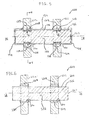
- FIG. 3 is a schematic cross sectional view of a rocker arm assembly.
- FIG. 4 is a side cross sectional view of the rocker arm assembly of FIG. 3 .
- FIG. 5 illustrates the rocker arm assembly of FIG. 3 with a portion of the shaft masked.
- FIG. 6 illustrates a schematic cross sectional view of the rocker arm assembly having a bearing surface having an outer surface treated with a surface finishing process.
- FIG. 1 illustrates a rocker arm assembly generally designated by element number 1.
- the rocker arm assembly 1 includes a hollow shaft 2 having a longitudinal axis A and four rocker arms 4 rotationally secured thereto.
- the rocker arms 4 rotationally and cyclically pivot with respect to the rocker arm shaft 2 about the longitudinal axis A as indicated by arrows marked P.
- a valve actuating device for an internal combustion engine is generally referred to as numeral 6.
- the valve actuating device 6 includes an intake valve 8 for selectively opening and closing an intake port 10 of a combustion chamber 12 defined in a cylinder head 14 of an internal combustion engine.
- a camshaft 16 includes an intake valve drive cam 18 for actuating the intake valve 8 and a pair of rocker arms 17A and 17B for jointly transmitting the lift of the intake valve drive cam 18 to the intake valve 8.
- the rocker arm 17A is shown rotatably mounted on a solid cylindrical rocker arm shaft 19.
- FIGS. 3-4 illustrate a portion of a rocker arm assembly 20 for use in overhead valve cylinder deactivation valve trains forming part of an internal combustion engine.
- the rocker arm assembly 20 includes two rocker arms 22 rotatably mounted on a solid, substantially cylindrical, rocker arm shaft 24 having a longitudinal axis A. During operation, the rocker arms 22 cyclically pivot as illustrated by the arrow R about the axis A.
- the rocker arm shaft 24 includes an outer surface 26 at least a portion of which defines a bearing surface 28 thereon.
- Each of the rocker arms 22 includes a substantially cylindrical inside wall 30 defining a bore extending therethrough. The inside wall 30 rotatably engages a contact portion 29 of the bearing surface 28.
- the rocker arm shaft 24 is shown having a core portion 32 defined by the outer surface 26 and located radially inward of the bearing surface 28.
- the bearing surface 28 has a surface hardness greater than that of the core portion 32, for improved wear resistance and deterrence of crack initiation and propagation.
- the rocker arm shaft 24 is manufactured from through hardened ASM 52100 steel and is further case hardened by carburization for increased wear resistance and deterrence of crack initiation and propagation.
- the carburization case hardening process includes one of gas diffusion, pack diffusion and liquid diffusion.
- the rocker arm shaft 24, in particular the bearing surface 28 is exposed to a carbon rich atmosphere (e.g., carbon monoxide, carbon powder, or a molten carbon rich bath) for a predetermined period of time.
- a carbon rich atmosphere e.g., carbon monoxide, carbon powder, or a molten carbon rich bath
- the carbon rich atmosphere is at a temperature between approximately 1550 °F to 1750 °F. The temperature and time are selected based on a desired surface hardness and penetration depth of the carbon.
- the rocker arm shaft 24 is cooled to a temperature of approximately 70 °F to achieve a desired surface hardness. Cooling can be accomplished by quenching in a liquid and/or by air cooling.
- the carburization process causes the bearing surface 28 to have a Rockwell hardness, C scale, of at least 59.
- the carburization process causes the bearing surface 28 and a portion of the shaft 24 radially inward therefrom to an effective case depth d, to have a carbon concentration greater than that of the core 32.
- the effective case depth d is a distance from a case hardened exterior surface to a furthest point, interior to the case hardened exterior surface, at which the Rockwell hardness, C scale, is about 50.
- the effective case depth d is measured perpendicular to the bearing surface. In one embodiment, the case depth d is about 0.063 inch (1.6002 mm).
- the present invention is not limited in this regard as the present invention is adaptable to other hardening processes including, but not limited to, nitriding wherein nitrogen is diffused into the bearing surface, carbonitriding wherein carbon and nitrogen are diffused into the bearing surface, flame hardening, induction hardening, laser beam hardening and electron beam hardening.
- Such a surface treatment process includes lapping-like scratching of the surface under extremely high compression of the surface to reduce slip planes, increase surface hardness, increase impact resistance, and increase surface compressive stresses by about twenty percent to a depth of about 0.012 inches. Surface roughness is reduced to less than 1 micro inch.
- Mikronite Technologies, Inc. of Eatontown, New Jersey has a Mikronite® brand surface treatment processes which can be employed.
- Another process that can deter crack initiation and propagation and increase impact, wear and corrosion resistance is a process using abrasive or non-abrasive media with or without chemical solutions, applied by vibratory methods.
- Such a process can provide: 1) a superfinished surface, defined as having an ISO Standard No. 4287 Arithmetic Mean Roughness of less than or equal to 2.5 micro inches; 2) an isotropic surface, defined as a surface having no orientation to its surface irregularities; and 3) a specular brightness, defined as a surface in which a clear reflection of an object can be seen.
- REM Chemicals, Inc. of Southington, Connecticut has an Isotropic Superfinish (ISF®) process that can be employed.
- the case hardened bearing surface 28 of FIG. 4 is treated with the Mikronite® and/or ISF® processes, either before or after carburization case hardening, such that the bearing surface 28 has an Arithmetic Mean Roughness of less than or equal to 2.5 micro inches, a specular brightness and/or is isotropic.
- FIG. 5 illustrates a rocker arm assembly 120, including two rocker arms 122 rotatably mounted on a solid, substantially cylindrical, rocker arm shaft 124 having a longitudinal axis 1A.
- the rocker arm shaft 124 includes an outer surface 126 at least a portion of which defines a bearing surface 128 on portions thereof as described below.
- Each of the rocker arms 122 includes a substantially cylindrical inside wall 130 defining a bore extending therethrough. The inside wall 130 rotatably engages the bearing surface 128 in the contact region 129.
- the rocker arm shaft 124 is shown having a core portion 132 defined by the outer surface and located radially inward of the bearing surface 128.
- the contact region 129 of the bearing surface 128 is case hardened by carburization to attain a surface hardness greater than that of the core portion 132, for example a Rockwell hardness, C scale, of at least 59.
- portions of the outer surface 126 beyond the contact region 129 are not case hardened and have a hardness about equal to that of the core portion 132.
- the effective case depth 1d of the case hardened surface of the contact region 129 is about 0.063 inch (1.6002 mm).
- Portions of the outer surface 126 which do not require hardening are coated with a mask 134 prior to initiation of the case hardening process.
- the mask 134 is made up of a substance impermeable to carbon, for example copper, to preclude diffusion of carbon into the portions of the outer surface 126 which do not require hardening.
- the mask 134 is deposited on the portions of the outer surface 126 which do not require hardening by an electro-chemical plating process. After case hardening, for example, carburizing, the mask 134 is removed.
- case hardening for example, carburizing
- the mask 134 is removed.
- the mask 134 is described as being copper, the present invention is not limited in this regard as other coatings are also suitable including but not limited to water soluble coatings.
- the portions of the outer surface 126 in the contact region 129, illustrated in FIG. 5 which are selectively case hardened and/or the portions of the outer surface 126 which do not require hardening, are treated with the Mikronite® and/or ISF® processes either before or after case hardening, such that the bearing surface 128 and/or outer surface 126 has an Arithmetic Mean Roughness of less than or equal to 2.5 micro inches, a specular brightness and/or is isotropic.
- a mask 134 similar to that described above for FIG. 5 , can be applied to a portion of the outer surface 126, prior to treatment of the rocker arm shaft 124 with the Mikronite® and/or ISF® processes for selectively surface treating the rocker arm shaft 124. The mask 134 is removed after such treatment.
- FIG. 6 illustrates a rocker arm assembly 220, including two rocker arms 222 rotatably mounted on a solid, substantially cylindrical, rocker arm shaft 224 having a longitudinal axis 2A.
- the rocker arm shaft 224 includes an outer surface 226 at least a portion of which defines bearing surface 228 thereon.
- Each of the rocker arms 222 includes a substantially cylindrical inside wall 230 defining a bore extending therethrough which rotatably engages the bearing surface 228 in the contact region 229.
- the rocker arm shaft 224 is shown having a core portion 232 defined by the outer surface 226 and located radially inward of the bearing surface 228.
- the bearing surface 228 has a ISO Standard No. 4287 Arithmetic Mean Roughness of less than or equal to 2.5 micro inches, providing a fine polished finish for improved wear resistance and for deterring crack initiation and propagation. In one embodiment the Arithmetic Mean Roughness is less than 1 micro inch. In one embodiment, the bearing surface 228 is isotropic having no orientation to its surface irregularities. In one embodiment, the bearing surface 228 has a specular brightness, defined as a surface in which a clear reflection of an object can be seen. In one embodiment, surface compressive stresses are increased by about twenty percent above pretreated conditions. Such increase in the surface compressive stresses is affected to a depth of about 0.012 inches.
- rocker arm shafts 28, 128 and 228 are illustrated as solid substantially cylindrical shafts, the present invention is not limited in this regard as other shaft configurations are adaptable for use in the present invention, including but not limited to case hardening and/or surface treatment of any portion of: hollow rocker arm shafts, rocker arm shafts with grooves for receiving and/or guiding the rocker arms and stepped rocker arm shafts having a plurality of different diameters.
Landscapes
- Engineering & Computer Science (AREA)
- Mechanical Engineering (AREA)
- General Engineering & Computer Science (AREA)
- Valve-Gear Or Valve Arrangements (AREA)
Applications Claiming Priority (1)
| Application Number | Priority Date | Filing Date | Title |
|---|---|---|---|
| US1993608P | 2008-01-09 | 2008-01-09 |
Publications (2)
| Publication Number | Publication Date |
|---|---|
| EP2078831A2 true EP2078831A2 (fr) | 2009-07-15 |
| EP2078831A3 EP2078831A3 (fr) | 2011-08-24 |
Family
ID=40568591
Family Applications (1)
| Application Number | Title | Priority Date | Filing Date |
|---|---|---|---|
| EP09150266A Withdrawn EP2078831A3 (fr) | 2008-01-09 | 2009-01-09 | Gaine de culbuteur à surface traitée |
Country Status (2)
| Country | Link |
|---|---|
| US (1) | US20090173301A1 (fr) |
| EP (1) | EP2078831A3 (fr) |
Cited By (2)
| Publication number | Priority date | Publication date | Assignee | Title |
|---|---|---|---|---|
| CN102242649A (zh) * | 2011-07-26 | 2011-11-16 | 奇瑞汽车股份有限公司 | 一种摇臂轴 |
| CN102308304B (zh) * | 2009-02-04 | 2013-08-21 | 海拉胡克双合有限公司 | 确定有效车道标记的方法和装置 |
Families Citing this family (4)
| Publication number | Priority date | Publication date | Assignee | Title |
|---|---|---|---|---|
| US20060067824A1 (en) * | 2004-09-30 | 2006-03-30 | O'hara Stephen J | Turbocharger with titanium component |
| US8915224B2 (en) * | 2010-12-18 | 2014-12-23 | Caterpillar Inc. | Rocker shaft shim |
| US20140091063A1 (en) * | 2012-09-28 | 2014-04-03 | Electro-Motive Diesel, Inc. | System for hardening a cylindrical metal component |
| CN111719109A (zh) * | 2020-06-30 | 2020-09-29 | 东科克诺尔商用车制动技术有限公司 | 一种解决转向器摇臂轴光轴和螺纹断裂的方法 |
Family Cites Families (25)
| Publication number | Priority date | Publication date | Assignee | Title |
|---|---|---|---|---|
| US4491500A (en) * | 1984-02-17 | 1985-01-01 | Rem Chemicals, Inc. | Method for refinement of metal surfaces |
| JPS61286501A (ja) * | 1985-06-12 | 1986-12-17 | Ngk Insulators Ltd | タ−ビンロ−タ−およびその製造法 |
| US4705594A (en) * | 1986-11-20 | 1987-11-10 | Rem Chemicals, Inc. | Composition and method for metal surface refinement |
| US4818333A (en) * | 1987-08-03 | 1989-04-04 | Rem Chemicals, Inc. | Metal surface refinement using dense alumina-based media |
| USRE34272E (en) * | 1989-05-04 | 1993-06-08 | Rem Chemicals, Inc. | Method and composition for refinement of metal surfaces |
| US4906327A (en) * | 1989-05-04 | 1990-03-06 | Rem Chemicals, Inc. | Method and composition for refinement of metal surfaces |
| US5158629A (en) * | 1989-08-23 | 1992-10-27 | Rem Chemicals, Inc. | Reducing surface roughness of metallic objects and burnishing liquid used |
| US5005544A (en) * | 1990-02-06 | 1991-04-09 | Spangler Earl M | Rocker shaft support system for internal combustion engine |
| US5158623A (en) * | 1990-03-30 | 1992-10-27 | Rem Chemicals, Inc. | Method for surface refinement of titanium and nickel |
| US5051141A (en) * | 1990-03-30 | 1991-09-24 | Rem Chemicals, Inc. | Composition and method for surface refinement of titanium nickel |
| JP3235236B2 (ja) * | 1992-12-28 | 2001-12-04 | スズキ株式会社 | 蒸発燃料制御装置 |
| US5507685A (en) * | 1993-08-25 | 1996-04-16 | Hoffman; Steve E. | Method for surface finishing of difficult polish surfaces |
| US5848929A (en) * | 1997-03-24 | 1998-12-15 | H Technology | Centrifugal finisher with fixed outer vessel and rotatable inner vessel |
| US6227942B1 (en) * | 1999-04-21 | 2001-05-08 | H-Semitran Llc | Ferrofluidic finishing |
| US6230676B1 (en) * | 1999-04-23 | 2001-05-15 | Toledo Technologies Inc. | Interchangeable rocker arm assembly |
| US20020088773A1 (en) * | 2001-01-10 | 2002-07-11 | Holland Jerry Dwayne | Nonabrasive media with accelerated chemistry |
| KR20030072018A (ko) * | 2002-03-05 | 2003-09-13 | 지엠대우오토앤테크놀로지주식회사 | 자동차용 로커암 샤프트의 완충구조 |
| DE10315416A1 (de) * | 2002-06-27 | 2004-01-22 | Ina-Schaeffler Kg | Lagefixierung eines Bolzens |
| JP2004060797A (ja) * | 2002-07-30 | 2004-02-26 | Koyo Seiko Co Ltd | ローラ部材およびその製造方法 |
| JP2005030582A (ja) * | 2003-01-31 | 2005-02-03 | Nsk Ltd | ニードル軸受、シャフト、カークーラコンプレッサ及び自動変速機用遊星歯車機構 |
| DE10306865B3 (de) * | 2003-02-19 | 2004-08-12 | Daimlerchrysler Ag | Verfahren zum Herstellen einer gehärteten Welle |
| US20050061600A1 (en) * | 2003-09-22 | 2005-03-24 | Holland Ronald A. | Automatic dual-function clutch |
| JP2005194986A (ja) * | 2004-01-09 | 2005-07-21 | Honda Motor Co Ltd | 弁作動特性可変装置 |
| US6962134B1 (en) * | 2004-08-05 | 2005-11-08 | General Motors Corporation | Rocker arm shaft retainer and assembly |
| JP2006144848A (ja) * | 2004-11-17 | 2006-06-08 | Jtekt Corp | ロッカアーム用軸受 |
-
2009
- 2009-01-02 US US12/348,032 patent/US20090173301A1/en not_active Abandoned
- 2009-01-09 EP EP09150266A patent/EP2078831A3/fr not_active Withdrawn
Cited By (2)
| Publication number | Priority date | Publication date | Assignee | Title |
|---|---|---|---|---|
| CN102308304B (zh) * | 2009-02-04 | 2013-08-21 | 海拉胡克双合有限公司 | 确定有效车道标记的方法和装置 |
| CN102242649A (zh) * | 2011-07-26 | 2011-11-16 | 奇瑞汽车股份有限公司 | 一种摇臂轴 |
Also Published As
| Publication number | Publication date |
|---|---|
| US20090173301A1 (en) | 2009-07-09 |
| EP2078831A3 (fr) | 2011-08-24 |
Similar Documents
| Publication | Publication Date | Title |
|---|---|---|
| EP2078831A2 (fr) | Gaine de culbuteur à surface traitée | |
| ES2259176T3 (es) | Seguidor de leva de rodillo para un motor. | |
| US6294029B1 (en) | Method of treating and smoothing sliding surface | |
| US20230160385A1 (en) | Pump actuator with stamp-aligned anti-rotation feature | |
| US20110308227A1 (en) | Method for producing a control chain | |
| EP1462669A2 (fr) | Palier à roulement | |
| US6131603A (en) | Ti alloy poppet valve and surface treatment thereof | |
| CN104540970A (zh) | 热处理钢构件的方法及钢构件 | |
| KR20060049014A (ko) | 밸브 리프터와, 그 형성 및 가공 방법 | |
| WO2008055064A1 (fr) | Poussoir pour un moteur à combustion interne | |
| JP2005030569A (ja) | カムフォロア | |
| JP2006009080A (ja) | 摺動部材及び該摺動部材の表面処理方法 | |
| JPH0142348B2 (fr) | ||
| EP2653671B1 (fr) | Came de commande à coeur et dispositif d'actionnement de soupape pour moteur | |
| JP5124947B2 (ja) | 金属材の疲労強度向上方法 | |
| JP4541941B2 (ja) | チタン合金製タペット等の部品とその製造方法 | |
| JP2000328183A (ja) | 鉄合金部品 | |
| JP2736631B2 (ja) | 摺動面とその表面処理方法 | |
| EP1273784A3 (fr) | Culasse pour un moteur à combustion interne à quatre temps | |
| US9828650B2 (en) | Method of manufacturing a sliding camshaft | |
| JP3411637B2 (ja) | 内燃機関用ロッカアームの製造方法 | |
| JP2006257942A5 (fr) | ||
| JP2004060807A (ja) | 転がり軸受 | |
| RU2259907C1 (ru) | Способ восстановления изношенных цилиндрических изделий | |
| CN111670309A (zh) | 具有油孔的连杆部件 |
Legal Events
| Date | Code | Title | Description |
|---|---|---|---|
| PUAI | Public reference made under article 153(3) epc to a published international application that has entered the european phase |
Free format text: ORIGINAL CODE: 0009012 |
|
| AK | Designated contracting states |
Kind code of ref document: A2 Designated state(s): AT BE BG CH CY CZ DE DK EE ES FI FR GB GR HR HU IE IS IT LI LT LU LV MC MK MT NL NO PL PT RO SE SI SK TR |
|
| AX | Request for extension of the european patent |
Extension state: AL BA RS |
|
| PUAL | Search report despatched |
Free format text: ORIGINAL CODE: 0009013 |
|
| AK | Designated contracting states |
Kind code of ref document: A3 Designated state(s): AT BE BG CH CY CZ DE DK EE ES FI FR GB GR HR HU IE IS IT LI LT LU LV MC MK MT NL NO PL PT RO SE SI SK TR |
|
| AX | Request for extension of the european patent |
Extension state: AL BA RS |
|
| RIC1 | Information provided on ipc code assigned before grant |
Ipc: F01L 1/18 20060101ALI20110721BHEP Ipc: F01L 1/053 20060101AFI20110721BHEP |
|
| AKY | No designation fees paid | ||
| REG | Reference to a national code |
Ref country code: DE Ref legal event code: R108 Effective date: 20120502 |
|
| STAA | Information on the status of an ep patent application or granted ep patent |
Free format text: STATUS: THE APPLICATION IS DEEMED TO BE WITHDRAWN |
|
| 18D | Application deemed to be withdrawn |
Effective date: 20120225 |