EP2078892B1 - Soupape à vide dotée d'une bague d'étanchéité - Google Patents
Soupape à vide dotée d'une bague d'étanchéité Download PDFInfo
- Publication number
- EP2078892B1 EP2078892B1 EP09000132A EP09000132A EP2078892B1 EP 2078892 B1 EP2078892 B1 EP 2078892B1 EP 09000132 A EP09000132 A EP 09000132A EP 09000132 A EP09000132 A EP 09000132A EP 2078892 B1 EP2078892 B1 EP 2078892B1
- Authority
- EP
- European Patent Office
- Prior art keywords
- valve
- sealing ring
- sealing
- radii
- vacuum valve
- Prior art date
- Legal status (The legal status is an assumption and is not a legal conclusion. Google has not performed a legal analysis and makes no representation as to the accuracy of the status listed.)
- Active
Links
Images
Classifications
-
- F—MECHANICAL ENGINEERING; LIGHTING; HEATING; WEAPONS; BLASTING
- F16—ENGINEERING ELEMENTS AND UNITS; GENERAL MEASURES FOR PRODUCING AND MAINTAINING EFFECTIVE FUNCTIONING OF MACHINES OR INSTALLATIONS; THERMAL INSULATION IN GENERAL
- F16K—VALVES; TAPS; COCKS; ACTUATING-FLOATS; DEVICES FOR VENTING OR AERATING
- F16K51/00—Other details not peculiar to particular types of valves or cut-off apparatus
- F16K51/02—Other details not peculiar to particular types of valves or cut-off apparatus specially adapted for high-vacuum installations
-
- F—MECHANICAL ENGINEERING; LIGHTING; HEATING; WEAPONS; BLASTING
- F16—ENGINEERING ELEMENTS AND UNITS; GENERAL MEASURES FOR PRODUCING AND MAINTAINING EFFECTIVE FUNCTIONING OF MACHINES OR INSTALLATIONS; THERMAL INSULATION IN GENERAL
- F16K—VALVES; TAPS; COCKS; ACTUATING-FLOATS; DEVICES FOR VENTING OR AERATING
- F16K1/00—Lift valves or globe valves, i.e. cut-off apparatus with closure members having at least a component of their opening and closing motion perpendicular to the closing faces
- F16K1/32—Details
- F16K1/34—Cutting-off parts, e.g. valve members, seats
- F16K1/36—Valve members
-
- F—MECHANICAL ENGINEERING; LIGHTING; HEATING; WEAPONS; BLASTING
- F16—ENGINEERING ELEMENTS AND UNITS; GENERAL MEASURES FOR PRODUCING AND MAINTAINING EFFECTIVE FUNCTIONING OF MACHINES OR INSTALLATIONS; THERMAL INSULATION IN GENERAL
- F16K—VALVES; TAPS; COCKS; ACTUATING-FLOATS; DEVICES FOR VENTING OR AERATING
- F16K1/00—Lift valves or globe valves, i.e. cut-off apparatus with closure members having at least a component of their opening and closing motion perpendicular to the closing faces
- F16K1/32—Details
- F16K1/34—Cutting-off parts, e.g. valve members, seats
- F16K1/42—Valve seats
-
- F—MECHANICAL ENGINEERING; LIGHTING; HEATING; WEAPONS; BLASTING
- F16—ENGINEERING ELEMENTS AND UNITS; GENERAL MEASURES FOR PRODUCING AND MAINTAINING EFFECTIVE FUNCTIONING OF MACHINES OR INSTALLATIONS; THERMAL INSULATION IN GENERAL
- F16K—VALVES; TAPS; COCKS; ACTUATING-FLOATS; DEVICES FOR VENTING OR AERATING
- F16K25/00—Details relating to contact between valve members and seats
Definitions
- the invention relates to a vacuum valve with a sealing ring, as it is known according to the features defined in the preamble of claim 1, for example from DE-A-34 45 236.
- a vacuum valve with a sealing ring, as it is known according to the features defined in the preamble of claim 1, for example from DE-A-34 45 236.
- DE-A-34 45 236 With the subject of DE 2947585 A1 also such a vacuum valve has become known, which is suitable to be arranged in a vacuum line in order to shut off negative pressures in the range from atmospheric pressure to ultrahigh vacuum.
- sealing rings For such vacuum valves, it is known to arrange so-called sealing rings between a valve disk and a housing-side valve seat.
- DE 294 75 85 A1 describes various embodiments of such sealing rings, wherein, for example, in FIG. 6 a rectangular sealing ring is shown, which undergoes a bend in the transition from the sealing position to the open position, which is strongly materielbe screwend.
- a sealing ring After the surfaces of this known sealing ring are conical, such a sealing ring is very difficult to produce. Because he has a relatively thin cross-section, undergoes a tilting in the transition from the closed position to the open position, there is the danger that when exposed to certain forces this ring over-snaps and no longer fulfills its sealing function. Thus, it runs on corresponding mating surfaces on the valve seat, picking up chips there and irreparably damages the sealing seat.
- the invention is therefore the object of developing a sealing ring for a vacuum valve according to the prior art so that it is easier to produce at substantially quadrangular cross-section, has a smaller Abrollweg and the risk of damaging the housing side arranged valve seats is not given ,
- the housing-side conical surface and the plate-side conical surface of the two opposing sealing seats are formed approximately equal.
- sealing ring is aligned in a horizontal plane and the diametrically opposite edges of the rectangular cross-section form the contact surfaces with the rectangular angle with respect to the housing side and the plate side valve seat.
- the sealing ring is formed of a metal material, such as stainless steel, high nickel alloys, and the like. It is of course also possible to use other suitable materials such. As metal-plastic composites, graphite, copper and bronze alloys.
- the housing with the housing-side seal seat is preferably formed of a stainless steel material, as well as formed on the plate side seal seat.
- the sealing ring according to the invention is very easy to produce, because it has no oblique or conical surfaces. Therefore, it does not slip in the sense of a cutting destruction of the housing-side and plate-side sealing surfaces, and the radii on the diametrically opposite edges are set so that an angle between an imaginary line between the two radius centers is approximately at right angles represents the two conical sealing surfaces, which in turn are formed approximately parallel to each other.
- the radii which determine the radius of curvature at the corners of the rectangular cross-section of the sealing ring can in extreme cases be increased so that they coincide (or even overlap slightly) in a single point.
- a relatively small radius of curvature is preferred, so that the two radius centers lie away from each other on a line which passes through one of the diametrically opposite edges of the rectangular cross section.
- the present invention purposely and purposefully departs from the knowledge of the prior art that self-deformation of the ring is necessary to achieve the required sealing forces. This is where the invention begins, which provides that the ring consists of a rectangular cross-section, which bends only slightly or not and that only the sealing forces on the relatively small-sized radii in relation to the obliquely opposite valve seats on the housing and the plate side be achieved.
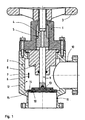
- FIG. 1 In FIG. 1 is generally shown that a drive housing 1 is connected via corresponding suitable screws with a valve housing 2.
- the drive housing 1 is penetrated by a spindle 4 which is rotatably connected to a handwheel 3.
- the spindle is in threaded engagement with an inside threaded bore in the drive housing 1, so that upon rotation of the handwheel 3, the valve rod 9 is moved in the direction of arrow 6 up or in the direction of arrow 7 down.
- valve housing 2 is provided with a guide 8 for the sealed guidance of the valve rod 9.
- the valve housing 2 thus forms an interior 12 into which an inlet flange 10 opens.
- an outlet flange 11 is arranged.
- inlet and outlet flange 10, 11 can be interchanged with each other. It does not matter from which side the medium flows and flows out.
- valve plate 13 is fixedly mounted, which in turn is connected to a sealing ring 14.
- a sealing ring 14 is now the effect of the sealing ring 14 with the plate-side valve seat 18 and the housing-side valve seat 15th
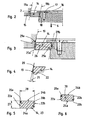
- FIGS. 2 and 3 Further details are from the FIGS. 2 and 3 refer to.
- the sealing ring 14 substantially consists of a rectangular cross-section 23, wherein the diametrically opposite corners of the rectangular cross-section 23 each have a radius 20a, 20b.
- the two radii 20a, 20b are approximately the same.
- the housing-side valve seat 15 is formed by a cone line 19a and at this oblique cone line, an angle of z. B. 10 ° to the vertical, the upper radius 20a of the sealing ring 14 is load-transmitting and sealing.
- valve-side valve seat 18 also has an approximately rectilinear cone line 19b and that, in turn, the radius 20b of the diametrically opposite edge bears against the radius 20a of the rectangular cross-section 23 at this cone line 19b.
- FIGS. 2 and 3 show that the sealing ring 14 is arranged horizontally, because it is held on its upper side by a disc 16 which is screwed by means of a screw 17 on the valve disc 13. He does not tilt and therefore does not tilt. It therefore moves linearly in the direction of arrow 6 in the opening direction and in the closing direction in the direction of arrow 7 along the two valve seats 15, 18th
- FIG. 3 shows that the two radius centers 25a, 25b of the two radii 20a, 20b lie on an imaginary connecting line 26, which connecting line exactly through the opposite edges of the rectangular cross section 23 and the housing side cone line 19a and the plate side cone line 19b at right angles 29a, 29b to cut.
- the angle 21 may be about 10 °, that is, it is important that only the diametrically opposed radii 20a, 20b come into sealing engagement with the associated valve seats 15, 18, but not the remaining parts of the sealing ring 14.
- the opposing straight lines 22a, 22b which describe the vertical lines of the rectangular cross section of the sealing ring 14, need not necessarily be parallel to one another, as the FIG. 5 shows. they are in the FIG. 5 formed as vertical lines.
- the mutually parallel straight lines 24a, 24b may be cambered or have peaks.
- the ratio of height 27 to width 28 of the rectangular cross-section results from the geometric requirement that namely a connecting line 26 through the two diametrically opposite edges, the opposite cone lines 19a, 19b at right angles each cut.
- the size of the radii 20a, 20b is relatively freely selectable, it must only be taken to ensure that the transmitted forces do not lead to damage of the housing side or plate-side valve seat 15, 18.
- the cone angle in the sealing seats 15, 18 are otherwise chosen so that the sealing ring 14 is not self-locking these valve seats 15, 18 loaded, but he is free on these valve seats 15, 18 movable from an open position to a closed position.
Landscapes
- Engineering & Computer Science (AREA)
- General Engineering & Computer Science (AREA)
- Mechanical Engineering (AREA)
- Details Of Valves (AREA)
- Lift Valve (AREA)
- Sliding Valves (AREA)
Claims (9)
- Soupape à vide dotée d'une bague d'étanchéité (14) entre deux surfaces coniques, de même orientation, de sièges de soupape (18, 15) d'une tête de soupape (13) et d'une enveloppe de soupape (2), étant précisé que la bague d'étanchéité (14) a une coupe transversale (23, 30) quadrangulaire, en particulier en forme de carré, de rectangle, de parallélogramme ou de losange, et qu'au moins deux arêtes de la bague espacées radialement l'une de l'autre ont des rayons de courbure (20a, 20b) qui, en position de soupape fermée, forment des surfaces d'étanchéité de soupape avec les surfaces coniques des sièges de soupape (18, 15), étant précisé que la bague d'étanchéité (14) n'est que faiblement élastique, caractérisée en ce que les rayons de courbure (20a, 20b) ne sont formés que dans deux coins diamétralement opposés de la coupe transversale (23, 30) de la bague d'étanchéité (14), et en ce que l'axe médian radial de la coupe transversale (23, 30) de la bague d'étanchéité (14) est perpendiculaire à l'axe médian axial de toute la bague d'étanchéité (14) et perpendiculaire au sens de mouvement (6, 7) de la tête de soupape (13).
- Soupape à vide selon la revendication 1, caractérisée en ce que les rayons de courbure (20a, 20b) de la bague d'étanchéité (14) sont de même taille ou de tailles différentes.
- Soupape à vide selon l'une des revendications 1 ou 2, caractérisée en ce qu'une ligne de liaison (26) qui traverse les deux centres (25a, 25b) des rayons de courbure (20a, 20b) coupe les deux surfaces coniques des sièges de soupape (18, 15) à angle droit.
- Soupape à vide selon l'une des revendications 1 à 3, caractérisée en ce que les rayons de courbure (20a, 20b) sont situés à des hauteurs différentes par rapport au sens de mouvement (6, 7) de la tête de soupape (13).
- Soupape à vide selon l'une des revendications 1 à 4, caractérisée en ce qu'un axe de symétrie de la bague d'étanchéité (14) est orienté dans un sens horizontal perpendiculairement au sens de mouvement (6, 7) de la tête de soupape (13).
- Soupape à vide selon l'une des revendications 1 à 5, caractérisée en ce que la bague d'étanchéité (14) se compose d'acier inoxydable, d'alliages à haute teneur en nickel, de matériaux composites métal-matière plastique, de matériaux à base de graphite ou d'alliages de cuivre et/ou de bronze.
- Soupape à vide selon l'une des revendications 1 à 6, caractérisée en ce que les surfaces coniques des sièges de soupape (15, 18), au moins, se composent d'un matériau à base d'acier spécial.
- Soupape à vide selon l'une des revendications 1 à 7, caractérisée en ce que la tête de soupape (13) est disposée sur une tige de soupape (9) mobile longitudinalement.
- Soupape à vide selon l'une des revendications 1 à 8, caractérisée en ce que la bague d'étanchéité (14) est fixée à la tête de soupape (13) ou à l'enveloppe de soupape (2) de manière amovible à l'aide de moyens de fixation (16, 17).
Applications Claiming Priority (1)
| Application Number | Priority Date | Filing Date | Title |
|---|---|---|---|
| DE102008003725A DE102008003725A1 (de) | 2008-01-09 | 2008-01-09 | Vakuum-Ventil mit Dichtring |
Publications (2)
| Publication Number | Publication Date |
|---|---|
| EP2078892A1 EP2078892A1 (fr) | 2009-07-15 |
| EP2078892B1 true EP2078892B1 (fr) | 2011-08-10 |
Family
ID=40380057
Family Applications (1)
| Application Number | Title | Priority Date | Filing Date |
|---|---|---|---|
| EP09000132A Active EP2078892B1 (fr) | 2008-01-09 | 2009-01-08 | Soupape à vide dotée d'une bague d'étanchéité |
Country Status (5)
| Country | Link |
|---|---|
| US (1) | US8328163B2 (fr) |
| EP (1) | EP2078892B1 (fr) |
| JP (1) | JP5388587B2 (fr) |
| AT (1) | ATE519979T1 (fr) |
| DE (1) | DE102008003725A1 (fr) |
Families Citing this family (20)
| Publication number | Priority date | Publication date | Assignee | Title |
|---|---|---|---|---|
| US10281047B2 (en) | 2011-04-12 | 2019-05-07 | Gasket International S.P.A. | Sealing system for industrial gate valves and gate valve comprising such a system |
| CN102168758B (zh) * | 2011-05-09 | 2014-05-07 | 北京航空航天大学 | 一种抽真空用密封卡口装置 |
| DE102012103641A1 (de) * | 2012-04-25 | 2013-10-31 | Bitzer Kühlmaschinenbau Gmbh | Absperrventil |
| RU2506482C1 (ru) * | 2012-07-26 | 2014-02-10 | Федеральное государственное бюджетное образовательное учреждение высшего профессионального образования Иркутский государственный университет путей сообщения (ФГБОУ ВПО ИрГУПС) | Клапан |
| EP3047514B1 (fr) * | 2013-09-20 | 2020-03-18 | Micromass UK Limited | Joint de chambre pour spectromètre de masse |
| CN103591303B (zh) * | 2013-11-20 | 2016-06-08 | 无锡智能自控工程股份有限公司 | 煤化工专用黑水防结焦耐冲抗振调节角阀 |
| KR102270597B1 (ko) | 2014-04-02 | 2021-06-29 | 배트 홀딩 아게 | 진공밸브 |
| KR102259116B1 (ko) | 2014-04-02 | 2021-06-01 | 배트 홀딩 아게 | 진공밸브 |
| CN104819314A (zh) * | 2015-05-23 | 2015-08-05 | 江苏江华阀业有限公司 | 无泄漏锥弧曲面密封湿氯专用阀 |
| JPWO2022030309A1 (fr) | 2020-08-03 | 2022-02-10 | ||
| CN116134254B (zh) | 2020-08-04 | 2025-11-07 | 伊格尔工业股份有限公司 | 阀 |
| JP7673070B2 (ja) | 2020-08-04 | 2025-05-08 | イーグル工業株式会社 | 弁 |
| EP4194726B1 (fr) | 2020-08-04 | 2025-11-19 | Eagle Industry Co., Ltd. | Soupape |
| US12298048B2 (en) | 2020-08-04 | 2025-05-13 | Eagle Industry Co., Ltd. | Expansion valve |
| US12264744B2 (en) | 2020-09-28 | 2025-04-01 | Eagle Industry Co., Ltd. | Valve |
| CN116457592A (zh) * | 2020-10-01 | 2023-07-18 | 伊格尔工业股份有限公司 | 阀 |
| KR102785818B1 (ko) | 2020-12-17 | 2025-03-26 | 이구루코교 가부시기가이샤 | 밸브 |
| JP7780506B2 (ja) | 2021-03-29 | 2025-12-04 | イーグル工業株式会社 | 弁 |
| CN115370754B (zh) * | 2021-05-17 | 2025-09-23 | 丹佛斯有限公司 | 流量控制阀 |
| DE102025100939A1 (de) | 2025-01-13 | 2026-07-16 | Hubert Bösch | Antrieb für ein Ventil und Ventil zum Schließen eines Vakuumrohrs |
Family Cites Families (20)
| Publication number | Priority date | Publication date | Assignee | Title |
|---|---|---|---|---|
| US3146006A (en) * | 1960-06-08 | 1964-08-25 | Parker Hannifin Corp | Boss joint with metallic seal ring |
| JPS5556959U (fr) * | 1978-10-11 | 1980-04-17 | ||
| CH637745A5 (de) * | 1979-02-01 | 1983-08-15 | Balzers Hochvakuum | Hochvakuumventil. |
| DE2947585C2 (de) * | 1979-11-26 | 1986-01-16 | VAT Aktiengesellschaft für Vakuum-Apparate-Technik, Haag | Dichtvorrichtung für den Verschluß eines aus Metall bestehenden Hochvakuumventils |
| EP0045141B1 (fr) * | 1980-07-24 | 1984-11-21 | British Nuclear Fuels PLC | Robinet à soupape à siège rapportée |
| JPS57143445U (fr) * | 1981-03-05 | 1982-09-08 | ||
| US4867338A (en) * | 1984-08-02 | 1989-09-19 | Boart International Limited | High temperature seal |
| DE3445236C1 (de) * | 1984-12-12 | 1986-03-06 | Schertler, Siegfried, Haag | Dichtvorrichtung fuer den Verschluss eines aus Metall bestehenden Hochvakuumventils |
| DE3834913A1 (de) * | 1988-10-13 | 1990-04-19 | Hubert Boesch | Dichtung fuer ventile oder flansche, insbesondere fuer die vakuumtechnik |
| US4922957A (en) * | 1989-03-08 | 1990-05-08 | National-Oilwell | Valve with replaceable seal element |
| US4923173A (en) * | 1989-10-30 | 1990-05-08 | Vilter Manufacturing Corporation | Seating seal means for disc-type valve |
| DE4446947C2 (de) | 1994-12-28 | 2003-04-10 | Vat Holding Ag Haag | Ringförmiger Dichtkörper |
| JPH08210518A (ja) * | 1995-02-03 | 1996-08-20 | Mitsubishi Heavy Ind Ltd | 弁装置 |
| JP3020569U (ja) * | 1995-03-30 | 1996-02-02 | 味の素株式会社 | バルブの弁体部構造 |
| US5533548A (en) * | 1995-05-18 | 1996-07-09 | Caterpillar Inc. | Valving interface for a poppet valve |
| JP2001349468A (ja) * | 2000-06-06 | 2001-12-21 | Smc Corp | 開閉バルブ |
| JP4754730B2 (ja) * | 2001-07-26 | 2011-08-24 | シーケーディ株式会社 | 手動式開閉弁 |
| US6698719B2 (en) * | 2002-06-26 | 2004-03-02 | Vat Holding Ag | Seal arrangement for a vacuum valve |
| JP2005321060A (ja) * | 2004-05-11 | 2005-11-17 | Kubota Corp | 高温用弁 |
| DE102005004987B8 (de) * | 2005-02-02 | 2017-12-14 | Vat Holding Ag | Vakuumventil |
-
2008
- 2008-01-09 DE DE102008003725A patent/DE102008003725A1/de not_active Withdrawn
-
2009
- 2009-01-08 EP EP09000132A patent/EP2078892B1/fr active Active
- 2009-01-08 AT AT09000132T patent/ATE519979T1/de active
- 2009-01-09 US US12/351,631 patent/US8328163B2/en active Active
- 2009-01-09 JP JP2009003481A patent/JP5388587B2/ja active Active
Also Published As
| Publication number | Publication date |
|---|---|
| JP2009174715A (ja) | 2009-08-06 |
| JP5388587B2 (ja) | 2014-01-15 |
| US8328163B2 (en) | 2012-12-11 |
| DE102008003725A1 (de) | 2009-07-16 |
| ATE519979T1 (de) | 2011-08-15 |
| EP2078892A1 (fr) | 2009-07-15 |
| US20090173905A1 (en) | 2009-07-09 |
Similar Documents
| Publication | Publication Date | Title |
|---|---|---|
| EP2078892A1 (fr) | Soupape à vide dotée d'une bague d'étanchéité | |
| EP1688654B1 (fr) | Clapet à vide | |
| DE2818633C2 (fr) | ||
| DE102014111407B4 (de) | Drehschieberventil | |
| CH686457A5 (de) | Platten-Schieber. | |
| DE2416071B2 (de) | Dichtungsanordnung für Hubventile | |
| EP3258149A1 (fr) | Soupape a vide destinee a reguler un flux et a interrompre un chemin d'ecoulement | |
| EP1235012A2 (fr) | Soupape coaxiale | |
| EP0829666B1 (fr) | Soupape | |
| EP3800315B1 (fr) | Module d'entrainement pour le deplacement d'un element de fermeture par rapport a un cadre dans une ouverture de batiment | |
| DE102008006384A1 (de) | Pneumatikzylinder | |
| EP3447346A1 (fr) | Soupape, en particulier servosoupape | |
| EP3236121B1 (fr) | Selecteur de circuit pour un systeme de soupape de securite et systeme de soupape de securite | |
| DD255575A5 (de) | Hubventil | |
| DE2732672C2 (de) | Kugelhahn | |
| EP0195178A2 (fr) | Vanne d'écoulement et d'arrêt | |
| EP2307775B1 (fr) | Corps de vanne | |
| DE2606042A1 (de) | Ventil zum absperren, drosseln oder regeln | |
| EP4098919B1 (fr) | Plaque de soupape permettant de rendre étanche une ouverture de soupape d'une soupape à vide | |
| DE2753771A1 (de) | Schieber | |
| EP3927997B1 (fr) | Entraînement à vis à billes avec dispositif d'antirotation | |
| DE19828896C1 (de) | Vorrichtung zur Abdichtung | |
| WO2001038159A1 (fr) | Valve de coupure destinee a des directions assistees notamment de vehicules automobiles | |
| DE2302457C3 (de) | Kettenschloß | |
| DE4000985C2 (de) | Dichtvorrichtung |
Legal Events
| Date | Code | Title | Description |
|---|---|---|---|
| PUAI | Public reference made under article 153(3) epc to a published international application that has entered the european phase |
Free format text: ORIGINAL CODE: 0009012 |
|
| AK | Designated contracting states |
Kind code of ref document: A1 Designated state(s): AT BE BG CH CY CZ DE DK EE ES FI FR GB GR HR HU IE IS IT LI LT LU LV MC MK MT NL NO PL PT RO SE SI SK TR |
|
| AX | Request for extension of the european patent |
Extension state: AL BA RS |
|
| 17P | Request for examination filed |
Effective date: 20091021 |
|
| AKX | Designation fees paid |
Designated state(s): AT CH DE FR GB IT LI |
|
| GRAP | Despatch of communication of intention to grant a patent |
Free format text: ORIGINAL CODE: EPIDOSNIGR1 |
|
| GRAS | Grant fee paid |
Free format text: ORIGINAL CODE: EPIDOSNIGR3 |
|
| GRAA | (expected) grant |
Free format text: ORIGINAL CODE: 0009210 |
|
| AK | Designated contracting states |
Kind code of ref document: B1 Designated state(s): AT CH DE FR GB IT LI |
|
| REG | Reference to a national code |
Ref country code: GB Ref legal event code: FG4D Free format text: NOT ENGLISH |
|
| REG | Reference to a national code |
Ref country code: CH Ref legal event code: EP |
|
| REG | Reference to a national code |
Ref country code: CH Ref legal event code: NV Representative=s name: LUCHS & PARTNER PATENTANWAELTE |
|
| REG | Reference to a national code |
Ref country code: DE Ref legal event code: R096 Ref document number: 502009001059 Country of ref document: DE Effective date: 20111013 |
|
| REG | Reference to a national code |
Ref country code: CH Ref legal event code: NV Representative=s name: LUCHS & PARTNER AG PATENTANWAELTE |
|
| PLBE | No opposition filed within time limit |
Free format text: ORIGINAL CODE: 0009261 |
|
| STAA | Information on the status of an ep patent application or granted ep patent |
Free format text: STATUS: NO OPPOSITION FILED WITHIN TIME LIMIT |
|
| 26N | No opposition filed |
Effective date: 20120511 |
|
| REG | Reference to a national code |
Ref country code: DE Ref legal event code: R097 Ref document number: 502009001059 Country of ref document: DE Effective date: 20120511 |
|
| PGFP | Annual fee paid to national office [announced via postgrant information from national office to epo] |
Ref country code: AT Payment date: 20140122 Year of fee payment: 6 |
|
| REG | Reference to a national code |
Ref country code: AT Ref legal event code: MM01 Ref document number: 519979 Country of ref document: AT Kind code of ref document: T Effective date: 20150108 |
|
| PG25 | Lapsed in a contracting state [announced via postgrant information from national office to epo] |
Ref country code: AT Free format text: LAPSE BECAUSE OF NON-PAYMENT OF DUE FEES Effective date: 20150108 |
|
| REG | Reference to a national code |
Ref country code: FR Ref legal event code: PLFP Year of fee payment: 8 |
|
| REG | Reference to a national code |
Ref country code: FR Ref legal event code: PLFP Year of fee payment: 9 |
|
| REG | Reference to a national code |
Ref country code: FR Ref legal event code: PLFP Year of fee payment: 10 |
|
| REG | Reference to a national code |
Ref country code: CH Ref legal event code: U11 Free format text: ST27 STATUS EVENT CODE: U-0-0-U10-U11 (AS PROVIDED BY THE NATIONAL OFFICE) Effective date: 20260201 |
|
| REG | Reference to a national code |
Ref country code: DE Ref legal event code: R082 Ref document number: 502009001059 Country of ref document: DE Representative=s name: DR. RIEBLING & PARTNER PATENTANWAELTE MBB, DE |
|
| PGFP | Annual fee paid to national office [announced via postgrant information from national office to epo] |
Ref country code: GB Payment date: 20260122 Year of fee payment: 18 |
|
| PGFP | Annual fee paid to national office [announced via postgrant information from national office to epo] |
Ref country code: DE Payment date: 20260120 Year of fee payment: 18 |
|
| PGFP | Annual fee paid to national office [announced via postgrant information from national office to epo] |
Ref country code: IT Payment date: 20260130 Year of fee payment: 18 |
|
| PGFP | Annual fee paid to national office [announced via postgrant information from national office to epo] |
Ref country code: FR Payment date: 20260123 Year of fee payment: 18 |
|
| PGFP | Annual fee paid to national office [announced via postgrant information from national office to epo] |
Ref country code: CH Payment date: 20260201 Year of fee payment: 18 |