EP2079089B1 - Appareil de commutation sous vide et procédé de diagnostic de pression sous vide - Google Patents
Appareil de commutation sous vide et procédé de diagnostic de pression sous vide Download PDFInfo
- Publication number
- EP2079089B1 EP2079089B1 EP08021300.2A EP08021300A EP2079089B1 EP 2079089 B1 EP2079089 B1 EP 2079089B1 EP 08021300 A EP08021300 A EP 08021300A EP 2079089 B1 EP2079089 B1 EP 2079089B1
- Authority
- EP
- European Patent Office
- Prior art keywords
- voltage
- condenser
- vacuum
- voltage indicator
- metal vessel
- Prior art date
- Legal status (The legal status is an assumption and is not a legal conclusion. Google has not performed a legal analysis and makes no representation as to the accuracy of the status listed.)
- Not-in-force
Links
- 238000000034 method Methods 0.000 title claims description 11
- 238000003745 diagnosis Methods 0.000 claims description 56
- 239000002184 metal Substances 0.000 claims description 49
- 229910052751 metal Inorganic materials 0.000 claims description 49
- 239000004020 conductor Substances 0.000 claims description 38
- 230000008878 coupling Effects 0.000 claims description 13
- 238000010168 coupling process Methods 0.000 claims description 13
- 238000005859 coupling reaction Methods 0.000 claims description 13
- 239000012212 insulator Substances 0.000 claims description 13
- 230000003068 static effect Effects 0.000 claims description 13
- 239000007787 solid Substances 0.000 claims description 11
- 239000000919 ceramic Substances 0.000 description 9
- 239000011248 coating agent Substances 0.000 description 7
- 238000000576 coating method Methods 0.000 description 7
- 238000005259 measurement Methods 0.000 description 3
- 238000001514 detection method Methods 0.000 description 2
- 239000003822 epoxy resin Substances 0.000 description 2
- 229920000647 polyepoxide Polymers 0.000 description 2
- 230000002441 reversible effect Effects 0.000 description 2
- 230000015556 catabolic process Effects 0.000 description 1
- 238000012790 confirmation Methods 0.000 description 1
- 238000006731 degradation reaction Methods 0.000 description 1
- 238000005516 engineering process Methods 0.000 description 1
- 238000007667 floating Methods 0.000 description 1
- 238000002955 isolation Methods 0.000 description 1
- 239000002923 metal particle Substances 0.000 description 1
- 230000000737 periodic effect Effects 0.000 description 1
- 229910000679 solder Inorganic materials 0.000 description 1
Images


Classifications
-
- H—ELECTRICITY
- H01—ELECTRIC ELEMENTS
- H01H—ELECTRIC SWITCHES; RELAYS; SELECTORS; EMERGENCY PROTECTIVE DEVICES
- H01H33/00—High-tension or heavy-current switches with arc-extinguishing or arc-preventing means
- H01H33/60—Switches wherein the means for extinguishing or preventing the arc do not include separate means for obtaining or increasing flow of arc-extinguishing fluid
- H01H33/66—Vacuum switches
- H01H33/668—Means for obtaining or monitoring the vacuum
Definitions
- the present invention relates to a vacuum switchgear having a diagnosis function and a method of diagnosing a vacuum pressure of a switch section.
- a vacuum-switchgear performs opening and closing of electrodes in a vacuum vessel, and the pressure in the vacuum vessel (vacuum pressure) may affect on a voltage withstanding performance and interruption characteristics of the switchgear.
- Fig. 4 shows a Paschen curve representing a discharge characteristic in vacuum, i.e. a relationship between a pressure and a discharge start voltage, wherein a vacuum isolation gap length is set to 5mm.
- the discharge start voltage depends on the vacuum pressure, which means the voltage withstanding performance and interruption characteristics depend on the vacuum pressure. Accordingly, the vacuum switchgear must be periodically diagnosed about normality or soundness of the vacuum pressure so as to guarantee the performance thereof.
- the diagnosis of the soundness of the vacuum pressure of the vacuum switchgear has been conducted by applying a predetermined high voltage between the electrodes thereby to detect a flashover.
- the switchgear must be power-cut at the time of diagnosis, and a high voltage power source for applying the high voltage is necessary.
- a cost and load for diagnosis increases.
- a switchgear wherein a measurement terminal for vacuum pressure diagnosis is disposed in opposed relation with respect to a metal vessel of a floating potential, in which the measurement terminal is molded together with the metal vessel in an insulator, and the measurement terminal is connected to a condenser one end of which is earthed.
- a voltage between the ends of the condenser is compared by means of a comparator with a predetermined threshold voltage, and a warning lamp, which is ON/OFF by a relay contact in response to an output of the comparator to thereby diagnose soundness of the vacuum pressure.
- EP 1 763 049 A1 describes a vacuum switchgear in line with the preamble of present claim 1.
- the vacuum switchgear having a vacuum pressure diagnosis function disclosed in the patent document No. 1 has a vacuum pressure diagnosis apparatus (51) is always connected to a terminal (50). Therefore, the diagnosis apparatus must be equipped to each of the vacuum switchgears.
- the present invention aims at providing a switchgear that is capable of performing easily diagnosis of soundness of a diagnosing apparatus for vacuum pressure and main circuits of the switchgear as well as soundness of vacuum pressure of a metal vessel.
- the present invention also aims at providing a method of diagnosing vacuum pressure that is capable of easily performing diagnosis of vacuum pressure of the vacuum switchgear with increased reliability.
- the present invention provides a vacuum switchgear as defined in claim 1 and a diagnosis method as defined in claim 5.
- the subclaims relate to preferred embodiments.
- the diagnosis of the vacuum pressure can be carried out easily because the diagnosis is done by observing the voltage indicators having lamps such as LEDs or buzzers, which are on the market.
- the voltage indicators are electrically connected to an connecting means such as connecting plugs disposed to the casing of the switchgear. That is, the diagnosis of the present invention does not need specific circuits or devices that are used in the patent document No. 1.
- the diagnosis of the present invention can be conducted with a high reliability because the diagnosis can be carried out after confirmation of the ON state of the main circuit of the switchgear or after diagnosis of the ON state of the main circuit using an inner diagnosis circuit the diagnosis of the vacuum pressure is done by the voltage indicator, i.e. by a two step method.
- a vacuum switchgear 1 comprises a switch section 100, an operating mechanism 3 for operating electrodes of the switch section 100.
- the operating mechanism 3 is disposed above the switch section 100, a bus bar 4 connected to the vacuum switch for supplying electric power to the switch section 100, a cable 5 for supplying electric power to a load side from the vacuum switch 100, and a casing 2 encasing the above components.
- the switch section 100 comprises a vacuum bulb 101 for a circuit breaker and a disconnector, a vacuum bulb 102 for an earth switch, a conductor 112 for connecting the vacuum bulb 101 and a bus bar 4, a bushing 113 for connecting the conductor 112 and the bus bar 4, a conductor 116 for connecting the vacuum bulb 101 and the cable 5, a second condenser 152 for detecting voltage, a coupling condenser 1001 for detecting voltage, and a condenser 1005 for diagnosing vacuum pressure of the vacuum bulb 101.
- the switch section 100 is encased in the casing 2 together with a condenser 1005 for diagnosing vacuum pressure of the vacuum vessel 12 and a condenser second for diagnosing a status of a main circuit of the switch section 100.
- the condensers 1005 and 152 are connected to a connecting means 1003 or 1006 disposed to the front panel 1002 of the casing, as shown in Fig. 1 .
- a voltage indicator 2000 is connected to the first connecting means 1006 or second connecting means 1003.
- the voltage indicator is available on the market as VOISOR+ (manufactured by Kries-Energietechnik GmbH & Co.), for example.
- the voltage indicator may indicate the state of the main circuit and/or vacuum pressure of the metal vessel by light (lamps) or sound, etc.
- the first condenser is connected to the second connecting means 1003 when the diagnosis of the main circuit of the vacuum switch is conducted. Normally, the diagnosis of the main circuit is done prior to the diagnosis of the vacuum pressure.
- the vacuum bulb 101 disposed in the switch section 100 and having interruption and disconnection characteristics comprises a metal vessel 12 in float potential, two pairs of fixed electrodes 110, 114 and movable electrodes 120, 121 disposed in the metal vessel 12 and in opposite relation.
- the fixed electrode 110 is supported by one end of the fixed conductor 111.
- the movable electrode 120 is supported by one end of the movable conductor 122, and the other end of the movable conductor 122 is connected to a connecting conductor 124.
- the fixed electrode 114 is supported by one end of the fixed conductor 115 and the other end of the fixed conductor 115 is connected to the conductor 116.
- An arc shield 119 is arranged around the fixed electrode 110 and the movable electrode 120 to prevent metal particles emitted from the electrodes at the time of interruption from adhesion on the inner face of the ceramic cylinders, the arc shield 119 being sandwiched between ceramic cylinders 118 surrounding the electrodes.
- the connecting conductor 124 is connected to an operating rod 126 by means of a ceramic rod 125.
- a bellows 130 is disposed between the operating rod 126 and the metal vessel 12 so as to operate the operating mechanism 3, keeping a vacuum condition of the switch section 100.
- the operating rod 126 extrudes from the metal vessel 12 of the switch section 101, and an end of the operating rod 126 located at the opposite position with respect to the ceramic rod 125 is supported by the insulating rod 127 and connected to the operating mechanism 3.
- the terminal 50 for diagnosis of the vacuum pressure is molded in integral with the solid insulator 20 on the metal vessel 12 to thereby electrically insulate the metal vessel 12 of the vacuum bulb 101 from the terminal 50.
- the terminal 50 is disposed outside of the metal vessel 12 and opposed to the metal vessel 12.
- the solid insulator 20 has a conductive coating 21 on its surface, and the coating is in an earth potential by earthing.
- the terminal 50 and the conductive coating 21 are electrically insulated from each other.
- the vacuum bulb 102 for an earth switch comprises an insulating ceramic cylinder 140 surrounding the fixed electrode 145 and the movable electrode 146, bellows 148, and terminal plates 141, 142 located at both ends of the ceramic cylinder.
- the movable electrode 146 opposed to the fixed electrode 145.
- the fixed electrode 145 is supported by one end of the fixed conductor 143, one end of which is connected to a conductor 116.
- the movable electrode 146 is supported by one end of the movable conductor 144, which is supported by the terminal plate 141 by means of the bellows 148. Part of the movable conductor 144 extrudes outwardly in the axial direction from the ceramic cylinder 140 and the terminal plates 141, 142.
- the bellows 148 follows the movement of the movable conductor 144, and the bellows 148 can air-tightly seal the space between the movable conductor 144 and the terminal plate 141.
- the end of the movable conductor 144, which is opposite to the end supported by the movable electrode 146 is connected to a connecting conductor 149, which is earthed, and the connecting conductor 149 is connected to an insulating rod 151 by means of a metal tool 150.
- the insulating rod 151 is connected to an operating mechanism 3 at its upper part. A high temperature solder bonds the components in the vacuum bulb 102 are bonded in a vacuum furnace.
- One end of the voltage detecting condenser 152 which is opposite to the end connected to the conductor 116, is connected to one end of a voltage detecting coupling condenser 1001, and the other end of the coupling condenser 1001 is earthed.
- the voltage indicator 2000 which is a plug in type, indicates the status of voltage application of the U, V, W switches of the switchgear 1. If all of the U, V, W switches are ON, the voltage indicator 2000 indicates the three switches are ON. If one or more of the switches are not ON, the indicator indicates one or more of the switches are OFF. According to this indication, the status of the power application of the switches is recognized.
- the voltage indicator 2000 may be equipped with LEDs, etc, which indicate information on the status. The voltage indicator 2000 can be detached from the connecting plugs 1003, 1006.
- the connecting plug 1003 is connected to both ends of the coupling condenser 1001 by means of a co-axial cable 1004 to apply the voltage of the coupling condenser 1001 to the connecting plug 1003.
- the connecting plug 1006 is used for connecting the voltage indicator 2000 to detect and indicate a status of vacuum pressure in the metal vessel 12 of the U, V, W switches. If vacuum of one of the metal vessels of the switches leaks to higher a vacuum pressure in the metal vessel, discharge may take place in the switch section 100 because of the presence of air therein so that a voltage of the metal vessel increases.
- the voltage indicator 2000 indicates the status of the vacuum in the metal vessels based on the voltage of the metal vessel. Accordingly, the vacuum status can be diagnosed by the indication on the indicator 2000. In this specification, the voltage indicator 2000 was used as a vacuum diagnosis means.
- a terminal 50 for diagnosis of vacuum pressure is molded in the solid insulator 20 such as epoxy resin is located outside of the metal vessel 12.
- the solid insulator 20 electrically separates terminal 50 from the metal vessel 12.
- the terminal 50 is connected to a vacuum diagnosis condenser 1005 one end of which is earthed.
- the both ends of the condenser 1005 are connected to the connecting plug 1003 by means of a co-axial cable 1007.
- the potential of the first condenser 1005 is applied to the connecting plug 1003.
- Electric power from the bus bar 4 is supplied to bushing 113 - conductor 112 - fixed conductor 111 - fixed electrode 110 - movable electrode 120 - movable conductor 122 - connecting conductor 124 - movable conductor 123 - movable electrode 121 - fixed electrode 114 - fixed conductor 115 - conductor 116 - bushing 117, and the electric power is supplied to the load side by means of cable 5.
- the operating mechanism 3 drives the insulating rod 127 up and down, the movable electrodes 120, 121 moves to three positions to form close position Y0, open position Y1 and disconnection position Y2 with the fixed electrodes 110, 114.
- the movement from the close position Y0 to open position Y1 performs an interruption function and the movement from the open position to the disconnection position Y2 performs a disconnection function.
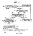
- the voltage indicator 2000 is connected to the connecting plug 1003 (step 200).
- a potential between the voltage detecting condenser 152 and the voltage detecting coupling condenser 1001 is equal to a partial voltage V1, which is represented as follows.
- V ⁇ 1 V / ⁇ 3 ⁇ C 152 / C 152 + C 1001
- the partial potential V1 is a product of a rate of a static capacitance C 152 of the second condenser 152 to the total capacitance of the capacitance C 152 of the condenser 152 and a capacitance C 1001 of the third condenser 1001 and the earth voltage V/ ⁇ 3. Accordingly, if a voltage proportional to V 1 is applied to the connecting plug 1003, the voltage indicator 2000 indicates that the main circuit is ON, and as a result, the voltage indicator 2000 is judged as sound (step 204).
- positions of the movable electrodes 120, 121 are checked if they are in the close positions. If they are not in the close position, they are moved to close positions by means of the operating mechanism 3. If the voltage indicator 200 turns on, the voltage indicator 200 is judged as sound (step 204). If the voltage indicator 200 does not turn on upon closing the switches, the voltage indicator 200 is judged as out of order (step 203). The voltage indicator 2000 is repaired or substituted with another voltage indicator.
- the voltage indicator 2000 is connected to the connecting plug 1006 (step 205).
- C 0 is a capacitance between the terminal 50 and the metal vessel 12 and C 1005 is a static capacitance of the vacuum pressure diagnosis condenser 1005.
- a voltage proportional to the partial potential V2 is applied between the first condenser and the connecting plug 1003, which is connected to the condenser 1005 by means of the co-axial cable 1007. If the voltage indicator 2000 turns on, the vacuum pressure is judged as sound (step 206), but if it turns on, the vacuum pressure in the metal vessel 12 is judged as not sound (step 207). If the vacuum pressure is judged as not sound, the vacuum bulb 101 or switch section 100 is repaired or exchanged with another one.
- the vacuum bulb 101 can be detected.
- the relationship between the static capacitance Co between the terminal 50 and the metal vessel 12 and the capacitance C 1005 of the first condenser 1005 is as follows.
- the driving voltage v of the voltage indicator 2000 should be equal to or smaller than V2. That is, v «V2.
- a ratio of the capacitance C 1005 of the condenser 1005 to the capacitance C 0 of the static capacitance C 0 is equal to or smaller than a ratio of a difference between v/ ⁇ 3 and the driving voltage of. the voltage indicator 2000 to the driving voltage v, soundness of the voltage pressure of then vacuum bulb 101 can be diagnosed.
- the terminal 50 is disposed in opposite relation to the metal vessel 12, one end of the vacuum pressure diagnosis condenser 1005 is connected to the terminal 50 and the other end thereof is earthed.
- the voltage indicator 2000 is connected to the first condenser by means of the co-axial cable 1007 and is connected to the connecting plug 1006.
- the voltage indicator is detachable from the connecting plug.
- the vacuum pressure is diagnosed by the voltage indicator 2000 upon demand.
- the portable voltage indicator 2000 is detachable, and can be used for diagnosis of the vacuum pressure of the switches on different sites. Therefore, the diagnosis is conducted economically.
- the terminal 50 is opposed to the metal vessel 12
- another member such as conductive film may be used instead of the terminal 50.
- the connecting plugs 1003 and 1006 are identical in the structure, one voltage indicator can be connected to them.
- the vacuum pressure of the metal vessel and the power application to the main circuit can be diagnosed with a single voltage indicator by changing the connecting plugs.
- the diagnosis of the voltage indicator 2000 itself can be done. Therefore, other circuit such as reversible circuits or elements for conducting diagnosis of the vacuum pressure, etc are not necessary, and hence the diagnosis of the present invention is economical and simple.
- the switch section 100 is covered with the solid insulator 20 such as epoxy resin together with the terminal 50, and the conductive coating 21 to be earthed is formed thereon.
- the conductive coating is earthed, operator or other stuffs are safe even if they touch the coating 21 or the solid insulator 20.
- the second condenser 152, third condenser (coupling condenser) 1001 and first condenser 1005 are disposed in the casing, but they may be arranged outside of the casing.
- the connecting means is connecting plugs 1003, 1006, but the voltage indicator 2000 can be electrically connected to the ends of the condensers 1001, 152 with various means such as screws, etc.
- the status of power application of the main circuit and the soundness of the voltage indicator are diagnosed prior to the diagnosis of the vacuum pressure. Therefore, the diagnosis is carried out safely and with high reliability.
- the diagnosis of the vacuum pressure of the switch section is conducted without increasing cost and making the structure complicated.
- the voltage indicator 2000 is equipped with several terminals for connecting to the connecting plugs 1003, 1006, the diagnosis of the switch section and the vacuum pressure can be conducted simultaneously.
- the connecting plugs 1003, 1006 are disposed on the front panel 1002 of the casing 2 so that operability and safety are increased.
- the connecting plugs can be disposed on other panels as long as operators or inspectors can observe the indication of the voltage indicator easily.
- the voltage indicator can be such that the status of the soundness of vacuum pressure or main switch or voltage indicator itself is output as sound, buzzer, etc.
- the first condenser 1005 and the connecting plug 1003 are connected to coupling condenser 1001 by means of the co-axial cables 1007, 1004.
- the wiring distance between the voltage indicator 200 and the third condenser 1001 or second condenser 152 is the same at any positions. Therefore, The capacitance generating on the wirings are the same at any positions so that it is possible to adjust voltages applied to the connecting plugs by means of the static capacitance of the first condenser 1005 and/or coupling condenser 1001.
Landscapes
- High-Tension Arc-Extinguishing Switches Without Spraying Means (AREA)
- Measuring Fluid Pressure (AREA)
Claims (8)
- Appareil de commutation à vide (1) comportant :un boîtier (2),un commutateur à vide (100), enfermé dans le boîtier (2), comprenant un récipient métallique (12) recouvert d'un isolateur solide (20), la surface de l'isolateur étant recouverte d'une couche conductrice (21) à mettre à la terre, et une paire d'une électrode mobile (122, 123) et d'une électrode fixe (111, 115) pour constituer un circuit principal d'une section de commutation (101), enfermée dans le récipient métallique,un premier condensateur (1005) relié à une borne (50) sur l'isolateur solide (20),un premier moyen de connexion électrique (1006) disposé dans le boîtier (2) et relié à un premier condensateur (1005) pour détecter une tension du récipient métallique (12), etun indicateur de tension (2000) qui est adapté pour indiquer un état de vide du récipient métallique (12) sur la base de la tension détectée, lorsque l'indicateur de tension (2000) est relié au premier moyen de connexion (1006),caractérisé en ce quel'appareil de commutation à vide (1) comporte en outre un second moyen de connexion (1003) disposé dans le boîtier (2) et relié à un second condensateur (152), lequel est relié à un condensateur de couplage (1001), etl'indicateur de tension (2000) est adapté pour indiquer un état d'application de puissance au circuit principal sur la base d'une tension appliquée au second moyen de connexion (1003), lorsque l'indicateur de tension (2000) est relié au second moyen de connexion (1003).
- Appareil de commutation à vide (1), dans lequel l'indicateur de tension (2000) est connectable à et déconnectable des premier et second moyens de connexion (1006, 1003).
- Appareil de commutation à vide (1) selon la revendication 1, dans lequel une extrémité du second condensateur (152) est reliée à un conducteur de côté de charge (116), et l'autre est reliée au condensateur de couplage (1001), l'autre extrémité du second condensateur (152) étant reliée au second moyen de connexion électrique (1003).
- Appareil de commutation à vide selon l'une quelconque des 1 à 3, dans lequel une tension de fonctionnement (V) de l'indicateur de tension (2000) satisfait à la relation

où V est la tension de ligne, C0 est une capacité statique entre la borne (50) et le récipient métallique (12), et c1005 est une capacité statique du premier condensateur (1005). - Procédé de diagnostic d'une pression de vide dans un récipient métallique (12) d'un appareil de commutation à vide (1) comportant : le récipient métallique (12), recouvert d'un isolateur solide (20) dont la surface est recouverte d'une couche conductrice (21) à mettre à la terre, au moins une paire d'une électrode mobile (122, 123) et d'une électrode fixe (111, 115), enfermées dans le récipient métallique (12) ; un premier condensateur (1005) relié à une borne (50) sur l'isolateur solide (20), un premier moyen de connexion électrique (1006) disposé dans un boîtier (2) contenant l'appareil de commutation à vide (1), le premier moyen de connexion électrique (1006) étant relié à une extrémité du premier condensateur (1005) et à la borne (50), et un second moyen de connexion électrique (1003) disposé dans le boîtier (2) et relié à un second condensateur (152) lequel est relié à un condensateur de couplage (1001), le procédé comportant les étapes consistant à :relier un indicateur de tension (2000) au second moyen de connexion (1003), un état d'application de puissance à un circuit principal de l'appareil de commutation (1) est indiqué sur l'indicateur de tension (2000) comme étant sous tension ou hors tension sur la base d'une tension appliquée au second moyen de connexion (1003) ;si l'indicateur de tension (2000) montre que le circuit principal est sous tension, relier l'indicateur de tension (2000) au premier moyen de connexion électrique (1006), de sorte que l'indicateur de tension (2000) indique un état de vide dans le récipient métallique (12) sur la base d'une tension détectée du récipient métallique (12) ; etdiagnostiquer la stabilité de la pression de vide dans le récipient métallique (12) sur la base de l'indication de l'indicateur de tension (2000).
- Procédé selon la revendication 5, dans lequel si l'indicateur de tension (2000) montre que le circuit principal est hors tension, la position de l'électrode mobile (122, 123) de l'appareil de commutation à vide (1) est vérifiée et, si elle n'est pas sous tension, l'électrode mobile (122, 123) est actionnée pour être fermée.
- Procédé selon la revendication 6, dans lequel si l'électrode mobile (122, 123) est dans une position fermée et si l'indicateur de tension (2000) montre que le circuit principal est fermé, il est déterminé que l'indicateur de tension (2000) est hors service.
- Procédé selon l'une quelconque des revendications 5 à 7, dans lequel une tension de fonctionnement v de l'indicateur de tension (2000) satisfait à la relation

où V est la tension de ligne, C0 est une capacité statique entre la borne (50) et le récipient métallique (12), et c1005 est une capacité statique du premier condensateur (1005).
Applications Claiming Priority (1)
| Application Number | Priority Date | Filing Date | Title |
|---|---|---|---|
| JP2008001750A JP4686555B2 (ja) | 2008-01-09 | 2008-01-09 | 真空開閉装置 |
Publications (3)
| Publication Number | Publication Date |
|---|---|
| EP2079089A2 EP2079089A2 (fr) | 2009-07-15 |
| EP2079089A3 EP2079089A3 (fr) | 2010-09-01 |
| EP2079089B1 true EP2079089B1 (fr) | 2015-09-23 |
Family
ID=40550565
Family Applications (1)
| Application Number | Title | Priority Date | Filing Date |
|---|---|---|---|
| EP08021300.2A Not-in-force EP2079089B1 (fr) | 2008-01-09 | 2008-12-08 | Appareil de commutation sous vide et procédé de diagnostic de pression sous vide |
Country Status (5)
| Country | Link |
|---|---|
| EP (1) | EP2079089B1 (fr) |
| JP (1) | JP4686555B2 (fr) |
| CN (1) | CN101483114B (fr) |
| SG (1) | SG154375A1 (fr) |
| TW (1) | TWI404099B (fr) |
Families Citing this family (7)
| Publication number | Priority date | Publication date | Assignee | Title |
|---|---|---|---|---|
| JP5350317B2 (ja) * | 2009-09-30 | 2013-11-27 | 株式会社日立製作所 | 真空開閉器、または開閉器用の電極もしくは真空開閉器の製造方法 |
| JP4982579B2 (ja) * | 2010-03-12 | 2012-07-25 | 株式会社日立製作所 | スイッチギヤ及びスイッチギヤの連動試験方法 |
| TWI485736B (zh) * | 2010-03-25 | 2015-05-21 | Hitachi Ltd | Vacuum switch and vacuum insulated switchgear |
| CN102280300A (zh) * | 2011-05-23 | 2011-12-14 | 宏秀电气(安徽)有限公司 | 一种可触摸的高压断路器 |
| JP6235830B2 (ja) * | 2013-08-22 | 2017-11-22 | 株式会社日立産機システム | 電圧検出器及びそれを備えたスイッチギヤ |
| CN106356246B (zh) * | 2016-11-03 | 2018-11-16 | 韩润萍 | 一种真空断路器灭弧室真空度在线监测装置 |
| CN110092571A (zh) * | 2019-06-13 | 2019-08-06 | 新沂市骄阳石英有限公司 | 一种石英砂熔炼炉压力提醒装置 |
Family Cites Families (15)
| Publication number | Priority date | Publication date | Assignee | Title |
|---|---|---|---|---|
| JPS5132829B1 (fr) * | 1969-04-11 | 1976-09-16 | ||
| JPS644203Y2 (fr) * | 1981-04-22 | 1989-02-03 | ||
| JPS5933719A (ja) * | 1982-08-17 | 1984-02-23 | 株式会社明電舎 | 真空しや断器の真空度監視装置 |
| JPS5923423A (ja) * | 1982-07-30 | 1984-02-06 | 株式会社明電舎 | 真空しや断器の真空度監視装置 |
| JPS61263015A (ja) * | 1985-05-16 | 1986-11-21 | 株式会社明電舎 | 真空インタラプタの真空度低下検出装置 |
| JPH01122530A (ja) * | 1987-11-06 | 1989-05-15 | Mitsubishi Electric Corp | 真空遮断器の遮断性能劣化予知装置 |
| JPH0325714A (ja) * | 1989-06-22 | 1991-02-04 | Sharp Corp | 磁気抵抗効果型薄膜磁気ヘッド |
| JP2885233B2 (ja) * | 1989-10-04 | 1999-04-19 | 富士電機株式会社 | 真空バルブ形開閉装置の真空度低下検出装置 |
| JP2705266B2 (ja) * | 1989-10-04 | 1998-01-28 | 富士電機株式会社 | 真空バルブ形開閉装置の真空度低下検出装置 |
| JP3168751B2 (ja) * | 1992-04-02 | 2001-05-21 | 富士電機株式会社 | 真空バルブの真空漏れ検知方法および装置 |
| JPH09261813A (ja) * | 1996-03-26 | 1997-10-03 | Nissin Electric Co Ltd | ガス絶縁開閉装置 |
| JP4953415B2 (ja) | 2005-09-12 | 2012-06-13 | 内山工業株式会社 | 燃料電池用構成部材のガスケット一体成型方法及びその成型装置 |
| JP4169024B2 (ja) * | 2005-09-13 | 2008-10-22 | 株式会社日立製作所 | 真空開閉装置 |
| JP4197702B2 (ja) * | 2006-01-31 | 2008-12-17 | 株式会社日立製作所 | 真空絶縁スイッチギヤ |
| JP4984577B2 (ja) * | 2006-03-08 | 2012-07-25 | 株式会社戸上電機製作所 | 検電装置を備えた開閉器 |
-
2008
- 2008-01-09 JP JP2008001750A patent/JP4686555B2/ja active Active
- 2008-12-02 TW TW97146777A patent/TWI404099B/zh active
- 2008-12-08 EP EP08021300.2A patent/EP2079089B1/fr not_active Not-in-force
- 2008-12-10 SG SG200809092-0A patent/SG154375A1/en unknown
-
2009
- 2009-01-08 CN CN 200910002218 patent/CN101483114B/zh not_active Expired - Fee Related
Also Published As
| Publication number | Publication date |
|---|---|
| SG154375A1 (en) | 2009-08-28 |
| JP4686555B2 (ja) | 2011-05-25 |
| CN101483114A (zh) | 2009-07-15 |
| TW200941531A (en) | 2009-10-01 |
| EP2079089A3 (fr) | 2010-09-01 |
| TWI404099B (zh) | 2013-08-01 |
| JP2009164018A (ja) | 2009-07-23 |
| CN101483114B (zh) | 2013-01-16 |
| EP2079089A2 (fr) | 2009-07-15 |
Similar Documents
| Publication | Publication Date | Title |
|---|---|---|
| EP2079089B1 (fr) | Appareil de commutation sous vide et procédé de diagnostic de pression sous vide | |
| US10262820B2 (en) | High voltage circuit breaker, system, vacuum interrupter module and associated drive module | |
| CA2590954C (fr) | Systeme de connecteur pour sectionneur isole avec capacite de mise a la terre et coupure visible | |
| JP2007508678A (ja) | シールド状態に封止された真空遮断器 | |
| JP4169024B2 (ja) | 真空開閉装置 | |
| WO2007097491A1 (fr) | Dispositif de détection de décharge partielle d'un appareil de commutation à isolation gazeuse | |
| KR20230087344A (ko) | 전력용 개폐기의 동작특성 모니터링 시스템 | |
| JP4728797B2 (ja) | ガス絶縁電力機器 | |
| JP6207805B1 (ja) | 真空バルブの真空劣化監視装置及びこれを備えた開閉装置 | |
| KR102870990B1 (ko) | 진공 인터럽터의 진공 상태 모니터링 장치 | |
| JP3321480B2 (ja) | 故障点標定システム | |
| JP2000050441A (ja) | 接地開閉器 | |
| JPH0965527A (ja) | 故障点標定システム | |
| JPS63213228A (ja) | 信号検出装置 | |
| JP2025500762A (ja) | 電力用開閉器の動作特性モニタリングシステム | |
| CN102201296A (zh) | 真空开关及真空绝缘开关装置 | |
| JPH0365008A (ja) | 予防保全システム | |
| JPH0287915A (ja) | ガス絶縁機器の分解ガス検出装置 | |
| JPH0833134A (ja) | ガス絶縁開閉装置及びその電流測定回路試験方法 | |
| JPH06174775A (ja) | 故障点標定システム | |
| JPH0365007A (ja) | 予防保全システム | |
| JPH0694775A (ja) | 故障点標定システム | |
| JPS63212831A (ja) | 流体圧力検出装置 | |
| HK1158813B (en) | Vacuum switch and vacuum insulated switch assembly | |
| HK1116917A (en) | Connector system for an insulated switch with provision for grounding and visible break |
Legal Events
| Date | Code | Title | Description |
|---|---|---|---|
| PUAI | Public reference made under article 153(3) epc to a published international application that has entered the european phase |
Free format text: ORIGINAL CODE: 0009012 |
|
| AK | Designated contracting states |
Kind code of ref document: A2 Designated state(s): AT BE BG CH CY CZ DE DK EE ES FI FR GB GR HR HU IE IS IT LI LT LU LV MC MT NL NO PL PT RO SE SI SK TR |
|
| AX | Request for extension of the european patent |
Extension state: AL BA MK RS |
|
| 17P | Request for examination filed |
Effective date: 20100331 |
|
| PUAL | Search report despatched |
Free format text: ORIGINAL CODE: 0009013 |
|
| AK | Designated contracting states |
Kind code of ref document: A3 Designated state(s): AT BE BG CH CY CZ DE DK EE ES FI FR GB GR HR HU IE IS IT LI LT LU LV MC MT NL NO PL PT RO SE SI SK TR |
|
| AX | Request for extension of the european patent |
Extension state: AL BA MK RS |
|
| AKX | Designation fees paid |
Designated state(s): AT BE BG CH CY CZ DE DK EE ES FI FR GB GR HR HU IE IS IT LI LT LU LV MC MT NL NO PL PT RO SE SI SK TR |
|
| GRAP | Despatch of communication of intention to grant a patent |
Free format text: ORIGINAL CODE: EPIDOSNIGR1 |
|
| INTG | Intention to grant announced |
Effective date: 20150407 |
|
| GRAS | Grant fee paid |
Free format text: ORIGINAL CODE: EPIDOSNIGR3 |
|
| GRAA | (expected) grant |
Free format text: ORIGINAL CODE: 0009210 |
|
| AK | Designated contracting states |
Kind code of ref document: B1 Designated state(s): AT BE BG CH CY CZ DE DK EE ES FI FR GB GR HR HU IE IS IT LI LT LU LV MC MT NL NO PL PT RO SE SI SK TR |
|
| REG | Reference to a national code |
Ref country code: GB Ref legal event code: FG4D |
|
| REG | Reference to a national code |
Ref country code: CH Ref legal event code: EP |
|
| REG | Reference to a national code |
Ref country code: AT Ref legal event code: REF Ref document number: 751617 Country of ref document: AT Kind code of ref document: T Effective date: 20151015 |
|
| REG | Reference to a national code |
Ref country code: IE Ref legal event code: FG4D |
|
| REG | Reference to a national code |
Ref country code: DE Ref legal event code: R096 Ref document number: 602008040270 Country of ref document: DE |
|
| REG | Reference to a national code |
Ref country code: NL Ref legal event code: FP |
|
| REG | Reference to a national code |
Ref country code: FR Ref legal event code: PLFP Year of fee payment: 8 |
|
| REG | Reference to a national code |
Ref country code: SE Ref legal event code: TRGR |
|
| PG25 | Lapsed in a contracting state [announced via postgrant information from national office to epo] |
Ref country code: NO Free format text: LAPSE BECAUSE OF FAILURE TO SUBMIT A TRANSLATION OF THE DESCRIPTION OR TO PAY THE FEE WITHIN THE PRESCRIBED TIME-LIMIT Effective date: 20151223 Ref country code: LV Free format text: LAPSE BECAUSE OF FAILURE TO SUBMIT A TRANSLATION OF THE DESCRIPTION OR TO PAY THE FEE WITHIN THE PRESCRIBED TIME-LIMIT Effective date: 20150923 Ref country code: LT Free format text: LAPSE BECAUSE OF FAILURE TO SUBMIT A TRANSLATION OF THE DESCRIPTION OR TO PAY THE FEE WITHIN THE PRESCRIBED TIME-LIMIT Effective date: 20150923 Ref country code: FI Free format text: LAPSE BECAUSE OF FAILURE TO SUBMIT A TRANSLATION OF THE DESCRIPTION OR TO PAY THE FEE WITHIN THE PRESCRIBED TIME-LIMIT Effective date: 20150923 Ref country code: GR Free format text: LAPSE BECAUSE OF FAILURE TO SUBMIT A TRANSLATION OF THE DESCRIPTION OR TO PAY THE FEE WITHIN THE PRESCRIBED TIME-LIMIT Effective date: 20151224 |
|
| REG | Reference to a national code |
Ref country code: LT Ref legal event code: MG4D |
|
| REG | Reference to a national code |
Ref country code: AT Ref legal event code: MK05 Ref document number: 751617 Country of ref document: AT Kind code of ref document: T Effective date: 20150923 |
|
| PG25 | Lapsed in a contracting state [announced via postgrant information from national office to epo] |
Ref country code: HR Free format text: LAPSE BECAUSE OF FAILURE TO SUBMIT A TRANSLATION OF THE DESCRIPTION OR TO PAY THE FEE WITHIN THE PRESCRIBED TIME-LIMIT Effective date: 20150923 |
|
| PG25 | Lapsed in a contracting state [announced via postgrant information from national office to epo] |
Ref country code: CZ Free format text: LAPSE BECAUSE OF FAILURE TO SUBMIT A TRANSLATION OF THE DESCRIPTION OR TO PAY THE FEE WITHIN THE PRESCRIBED TIME-LIMIT Effective date: 20150923 Ref country code: SK Free format text: LAPSE BECAUSE OF FAILURE TO SUBMIT A TRANSLATION OF THE DESCRIPTION OR TO PAY THE FEE WITHIN THE PRESCRIBED TIME-LIMIT Effective date: 20150923 Ref country code: ES Free format text: LAPSE BECAUSE OF FAILURE TO SUBMIT A TRANSLATION OF THE DESCRIPTION OR TO PAY THE FEE WITHIN THE PRESCRIBED TIME-LIMIT Effective date: 20150923 Ref country code: EE Free format text: LAPSE BECAUSE OF FAILURE TO SUBMIT A TRANSLATION OF THE DESCRIPTION OR TO PAY THE FEE WITHIN THE PRESCRIBED TIME-LIMIT Effective date: 20150923 Ref country code: IS Free format text: LAPSE BECAUSE OF FAILURE TO SUBMIT A TRANSLATION OF THE DESCRIPTION OR TO PAY THE FEE WITHIN THE PRESCRIBED TIME-LIMIT Effective date: 20160123 |
|
| PGFP | Annual fee paid to national office [announced via postgrant information from national office to epo] |
Ref country code: IT Payment date: 20151218 Year of fee payment: 8 |
|
| PG25 | Lapsed in a contracting state [announced via postgrant information from national office to epo] |
Ref country code: AT Free format text: LAPSE BECAUSE OF FAILURE TO SUBMIT A TRANSLATION OF THE DESCRIPTION OR TO PAY THE FEE WITHIN THE PRESCRIBED TIME-LIMIT Effective date: 20150923 Ref country code: RO Free format text: LAPSE BECAUSE OF FAILURE TO SUBMIT A TRANSLATION OF THE DESCRIPTION OR TO PAY THE FEE WITHIN THE PRESCRIBED TIME-LIMIT Effective date: 20150923 Ref country code: BE Free format text: LAPSE BECAUSE OF NON-PAYMENT OF DUE FEES Effective date: 20151231 Ref country code: PT Free format text: LAPSE BECAUSE OF FAILURE TO SUBMIT A TRANSLATION OF THE DESCRIPTION OR TO PAY THE FEE WITHIN THE PRESCRIBED TIME-LIMIT Effective date: 20160125 Ref country code: PL Free format text: LAPSE BECAUSE OF FAILURE TO SUBMIT A TRANSLATION OF THE DESCRIPTION OR TO PAY THE FEE WITHIN THE PRESCRIBED TIME-LIMIT Effective date: 20150923 |
|
| REG | Reference to a national code |
Ref country code: DE Ref legal event code: R097 Ref document number: 602008040270 Country of ref document: DE |
|
| PG25 | Lapsed in a contracting state [announced via postgrant information from national office to epo] |
Ref country code: MC Free format text: LAPSE BECAUSE OF FAILURE TO SUBMIT A TRANSLATION OF THE DESCRIPTION OR TO PAY THE FEE WITHIN THE PRESCRIBED TIME-LIMIT Effective date: 20150923 Ref country code: LU Free format text: LAPSE BECAUSE OF FAILURE TO SUBMIT A TRANSLATION OF THE DESCRIPTION OR TO PAY THE FEE WITHIN THE PRESCRIBED TIME-LIMIT Effective date: 20151208 |
|
| PLBE | No opposition filed within time limit |
Free format text: ORIGINAL CODE: 0009261 |
|
| STAA | Information on the status of an ep patent application or granted ep patent |
Free format text: STATUS: NO OPPOSITION FILED WITHIN TIME LIMIT |
|
| 26N | No opposition filed |
Effective date: 20160624 |
|
| PG25 | Lapsed in a contracting state [announced via postgrant information from national office to epo] |
Ref country code: DK Free format text: LAPSE BECAUSE OF FAILURE TO SUBMIT A TRANSLATION OF THE DESCRIPTION OR TO PAY THE FEE WITHIN THE PRESCRIBED TIME-LIMIT Effective date: 20150923 |
|
| REG | Reference to a national code |
Ref country code: NL Ref legal event code: MM Effective date: 20160101 |
|
| REG | Reference to a national code |
Ref country code: IE Ref legal event code: MM4A |
|
| PG25 | Lapsed in a contracting state [announced via postgrant information from national office to epo] |
Ref country code: NL Free format text: LAPSE BECAUSE OF NON-PAYMENT OF DUE FEES Effective date: 20160101 Ref country code: IE Free format text: LAPSE BECAUSE OF NON-PAYMENT OF DUE FEES Effective date: 20151208 |
|
| REG | Reference to a national code |
Ref country code: FR Ref legal event code: PLFP Year of fee payment: 9 |
|
| PG25 | Lapsed in a contracting state [announced via postgrant information from national office to epo] |
Ref country code: SI Free format text: LAPSE BECAUSE OF FAILURE TO SUBMIT A TRANSLATION OF THE DESCRIPTION OR TO PAY THE FEE WITHIN THE PRESCRIBED TIME-LIMIT Effective date: 20150923 |
|
| PG25 | Lapsed in a contracting state [announced via postgrant information from national office to epo] |
Ref country code: BE Free format text: LAPSE BECAUSE OF FAILURE TO SUBMIT A TRANSLATION OF THE DESCRIPTION OR TO PAY THE FEE WITHIN THE PRESCRIBED TIME-LIMIT Effective date: 20150923 |
|
| PGFP | Annual fee paid to national office [announced via postgrant information from national office to epo] |
Ref country code: FR Payment date: 20161111 Year of fee payment: 9 Ref country code: GB Payment date: 20161207 Year of fee payment: 9 Ref country code: CH Payment date: 20161213 Year of fee payment: 9 Ref country code: DE Payment date: 20161129 Year of fee payment: 9 |
|
| PGFP | Annual fee paid to national office [announced via postgrant information from national office to epo] |
Ref country code: SE Payment date: 20161213 Year of fee payment: 9 |
|
| PG25 | Lapsed in a contracting state [announced via postgrant information from national office to epo] |
Ref country code: HU Free format text: LAPSE BECAUSE OF FAILURE TO SUBMIT A TRANSLATION OF THE DESCRIPTION OR TO PAY THE FEE WITHIN THE PRESCRIBED TIME-LIMIT; INVALID AB INITIO Effective date: 20081208 Ref country code: BG Free format text: LAPSE BECAUSE OF FAILURE TO SUBMIT A TRANSLATION OF THE DESCRIPTION OR TO PAY THE FEE WITHIN THE PRESCRIBED TIME-LIMIT Effective date: 20150923 |
|
| PG25 | Lapsed in a contracting state [announced via postgrant information from national office to epo] |
Ref country code: CY Free format text: LAPSE BECAUSE OF FAILURE TO SUBMIT A TRANSLATION OF THE DESCRIPTION OR TO PAY THE FEE WITHIN THE PRESCRIBED TIME-LIMIT Effective date: 20150923 |
|
| PG25 | Lapsed in a contracting state [announced via postgrant information from national office to epo] |
Ref country code: TR Free format text: LAPSE BECAUSE OF FAILURE TO SUBMIT A TRANSLATION OF THE DESCRIPTION OR TO PAY THE FEE WITHIN THE PRESCRIBED TIME-LIMIT Effective date: 20150923 Ref country code: MT Free format text: LAPSE BECAUSE OF FAILURE TO SUBMIT A TRANSLATION OF THE DESCRIPTION OR TO PAY THE FEE WITHIN THE PRESCRIBED TIME-LIMIT Effective date: 20150923 |
|
| PG25 | Lapsed in a contracting state [announced via postgrant information from national office to epo] |
Ref country code: IT Free format text: LAPSE BECAUSE OF NON-PAYMENT OF DUE FEES Effective date: 20161208 |
|
| REG | Reference to a national code |
Ref country code: DE Ref legal event code: R119 Ref document number: 602008040270 Country of ref document: DE |
|
| REG | Reference to a national code |
Ref country code: CH Ref legal event code: PL |
|
| GBPC | Gb: european patent ceased through non-payment of renewal fee |
Effective date: 20171208 |
|
| PG25 | Lapsed in a contracting state [announced via postgrant information from national office to epo] |
Ref country code: SE Free format text: LAPSE BECAUSE OF NON-PAYMENT OF DUE FEES Effective date: 20171209 |
|
| REG | Reference to a national code |
Ref country code: FR Ref legal event code: ST Effective date: 20180831 |
|
| PG25 | Lapsed in a contracting state [announced via postgrant information from national office to epo] |
Ref country code: DE Free format text: LAPSE BECAUSE OF NON-PAYMENT OF DUE FEES Effective date: 20180703 Ref country code: FR Free format text: LAPSE BECAUSE OF NON-PAYMENT OF DUE FEES Effective date: 20180102 |
|
| PG25 | Lapsed in a contracting state [announced via postgrant information from national office to epo] |
Ref country code: CH Free format text: LAPSE BECAUSE OF NON-PAYMENT OF DUE FEES Effective date: 20171231 Ref country code: LI Free format text: LAPSE BECAUSE OF NON-PAYMENT OF DUE FEES Effective date: 20171231 Ref country code: GB Free format text: LAPSE BECAUSE OF NON-PAYMENT OF DUE FEES Effective date: 20171208 |