EP2079143B1 - Procédé et dispositif pour déterminer la marge de stabilité de tension pour un délestage dans un système d'alimentation électrique - Google Patents
Procédé et dispositif pour déterminer la marge de stabilité de tension pour un délestage dans un système d'alimentation électrique Download PDFInfo
- Publication number
- EP2079143B1 EP2079143B1 EP20080159312 EP08159312A EP2079143B1 EP 2079143 B1 EP2079143 B1 EP 2079143B1 EP 20080159312 EP20080159312 EP 20080159312 EP 08159312 A EP08159312 A EP 08159312A EP 2079143 B1 EP2079143 B1 EP 2079143B1
- Authority
- EP
- European Patent Office
- Prior art keywords
- power system
- load
- voltage
- cos
- stability
- Prior art date
- Legal status (The legal status is an assumption and is not a legal conclusion. Google has not performed a legal analysis and makes no representation as to the accuracy of the status listed.)
- Not-in-force
Links
Images

Classifications
-
- H—ELECTRICITY
- H02—GENERATION; CONVERSION OR DISTRIBUTION OF ELECTRIC POWER
- H02J—ELECTRIC POWER NETWORKS; CIRCUIT ARRANGEMENTS OR SYSTEMS FOR SUPPLYING OR DISTRIBUTING ELECTRIC POWER; SYSTEMS FOR STORING ELECTRIC ENERGY
- H02J3/00—Circuit arrangements for AC mains or AC distribution networks
- H02J3/12—Arrangements for adjusting voltage in AC networks by changing a characteristic of the network load
- H02J3/14—Arrangements for adjusting voltage in AC networks by changing a characteristic of the network load by switching loads on to, or off from, the networks, e.g. progressively balanced loading
-
- H—ELECTRICITY
- H02—GENERATION; CONVERSION OR DISTRIBUTION OF ELECTRIC POWER
- H02J—ELECTRIC POWER NETWORKS; CIRCUIT ARRANGEMENTS OR SYSTEMS FOR SUPPLYING OR DISTRIBUTING ELECTRIC POWER; SYSTEMS FOR STORING ELECTRIC ENERGY
- H02J3/00—Circuit arrangements for AC mains or AC distribution networks
- H02J3/001—Arrangements for handling faults or abnormalities, e.g. emergencies or contingencies
- H02J3/0014—Arrangements for handling faults or abnormalities, e.g. emergencies or contingencies for preventing or reducing power oscillations in networks
-
- Y—GENERAL TAGGING OF NEW TECHNOLOGICAL DEVELOPMENTS; GENERAL TAGGING OF CROSS-SECTIONAL TECHNOLOGIES SPANNING OVER SEVERAL SECTIONS OF THE IPC; TECHNICAL SUBJECTS COVERED BY FORMER USPC CROSS-REFERENCE ART COLLECTIONS [XRACs] AND DIGESTS
- Y02—TECHNOLOGIES OR APPLICATIONS FOR MITIGATION OR ADAPTATION AGAINST CLIMATE CHANGE
- Y02B—CLIMATE CHANGE MITIGATION TECHNOLOGIES RELATED TO BUILDINGS, e.g. HOUSING, HOUSE APPLIANCES OR RELATED END-USER APPLICATIONS
- Y02B70/00—Technologies for an efficient end-user side electric power management and consumption
- Y02B70/30—Systems integrating technologies related to power network operation and communication or information technologies for improving the carbon footprint of the management of residential or tertiary loads, i.e. smart grids as climate change mitigation technology in the buildings sector, including also the last stages of power distribution and the control, monitoring or operating management systems at local level
- Y02B70/3225—Demand response systems, e.g. load shedding, peak shaving
-
- Y—GENERAL TAGGING OF NEW TECHNOLOGICAL DEVELOPMENTS; GENERAL TAGGING OF CROSS-SECTIONAL TECHNOLOGIES SPANNING OVER SEVERAL SECTIONS OF THE IPC; TECHNICAL SUBJECTS COVERED BY FORMER USPC CROSS-REFERENCE ART COLLECTIONS [XRACs] AND DIGESTS
- Y04—INFORMATION OR COMMUNICATION TECHNOLOGIES HAVING AN IMPACT ON OTHER TECHNOLOGY AREAS
- Y04S—SYSTEMS INTEGRATING TECHNOLOGIES RELATED TO POWER NETWORK OPERATION, COMMUNICATION OR INFORMATION TECHNOLOGIES FOR IMPROVING THE ELECTRICAL POWER GENERATION, TRANSMISSION, DISTRIBUTION, MANAGEMENT OR USAGE, i.e. SMART GRIDS
- Y04S20/00—Management or operation of end-user stationary applications or the last stages of power distribution; Controlling, monitoring or operating thereof
- Y04S20/20—End-user application control systems
- Y04S20/222—Demand response systems, e.g. load shedding, peak shaving
Definitions
- This invention relates to a method of determining voltage stability margin within an electrical power system, and an apparatus for monitoring voltage stability limits within an electrical power system and for dynamic control of load shedding and restoration.
- the last line of defense which prevents the voltage collapse is the load shedding at the stations, where the voltage stability margin becomes too low.
- Conventional monitoring systems compare electrical power system frequency, rate of frequency change, voltage level, rate of voltage decay, power flow levels, with a fixed reference value, and indicate that the power system has become unstable when the voltage, frequency has fallen below the reference value.
- the devices monitor the frequency and / or voltage with fixed settings at which the load shedding can be initiated in steps when the frequency or voltage has declined to an agreed-to level.
- the essence of the invention is the fact that the derivative of the apparent power against the load admittance may be used to determine the stability margin and to initiate the load shedding if the margin becomes too low.
- the invention refers to the method of claim 1 and to the apparatus of claim 5.
- a method of monitoring voltage stability within an electrical power system comprising the steps of:
- the method of monitoring voltage stability within an electrical power system includes the steps of:
- the foregoing steps establish additional criteria for determining whether to take remedial action, in the form of load shedding, following an indication that the power system has become unstable.
- the dynamic voltage operating point varies according to changes within the power system, and so is a reflection of the actual status of the power system. Accordingly these steps help to further reduce the incidence of unnecessary intervention to restore stability to a power system, and so reduce the inconvenience caused to users of the power system.
- the method is based on the definition of the voltage stability and calculates the ratio as the derivative of load apparent power against load admittance. Such a factor provides a very good indication of the level of voltage stability within a power system, and so allows for an accurate determination of whether the power system has become unstable.
- S is the load apparent power
- V is the power system voltage
- Z S is the source impedance
- Z L is the load impedance
- ⁇ is the dynamic phase angle difference between the source and load of the power system.
- the method includes measuring ⁇ L in the power system and determining ⁇ S by estimation.
- Such steps establish a dynamic power system stability margin which accurately reflects the level of stability within the power system and may be used to determine the amount of load to be shed.
- the method of monitoring stability within an electrical power system may further include assigning (Z S Y) a predetermined value. This helps continuously (dynamically) reset the voltage operating point at a suitable level which continues to vary according to changes within the power system because of its dependence on the ⁇ .
- the method of monitoring voltage stability within an electrical power system further includes the steps of:
- the foregoing steps enable the method to adapt to the level and nature of the voltage instability within the power system and modify the amount of load which is shed or reintroduced according to, for example, whether the power system is moving closer towards becoming stable, or moving further away from becoming stable.
- the method of monitoring voltage stability within an electrical power system further includes the step of monitoring the load admittance of the power system and only establishing a dynamic voltage system stability margin following detection of a change in the load admittance.
- This step prevents any erroneous indication that the power system has become unstable following changes in the source voltage or impedance.
- an apparatus for monitoring voltage stability within an electrical power system comprising:
- the apparatus of the invention includes:
- a restoration module to automatically restore the load when margin (M) and/or DV ratios return to the predetermined set values.
- the apparatus of the invention shares the advantages of the corresponding method steps of the invention.
- Basing the dynamic power system stability margin on an operating characteristic of the power system allows the stability margin to adapt to changes within the power system such as, for example, changes in configuration of buses, lines and loads within the power system.
- S is the load apparent power
- V the power system voltage
- Z S is the source impedance
- Z L is the load impedance
- ⁇ is the dynamic phase angle difference between the source and load of the power system.
- Thevenin equivalent circuit 10 of the electrical power system is shown in Figure 1 .
- the circuit 10 includes a source equivalent electromotive force (EMF) 12, the source impedance 14, and the load impedance 16.
- EMF electromotive force
- the power system voltage V lies across the load impedance 16.
- Determining ⁇ dynamically means that the derivative of load apparent power against load admittance d S d Y continuously reflects the actual status of the power system stability.
- the load phase angle ⁇ L is measured in the power system, while the source phase angle ⁇ S is arrived at by estimation.
- the source phase angle ⁇ S may be estimated is by making phasor measurements at different points of the system and comparing those with the phasor measured at the reference point in the system.
- Another way of estimating relies on the measurement of the line current of the incoming line into the substation and the line parameters (R) and (X) and estimating phase angle by calculating it from the line impedance complex value.
- the method of maintaining stability within an electrical power system according to the first embodiment of the invention also includes the steps, following an indication that the power system has become unstable, of:
- (Z S Y) is assigned a predetermined value. Typically this depends upon the rate of degrading voltage stability within the system and is a recommended value that is arrived at through extensive testing to establish most optimized rule for setting the voltage operating point.
- the first embodiment method also includes determining whether the level of disturbance within the electrical power system is changing; and reconnecting one or more loads if the level of disturbance within the electrical power system is decreasing.
- a decreasing level of disturbance within the power system indicates that the power system is moving towards stability, and so it is possible to reintroduce one or more loads into the power system so as to minimise any inconvenience to users of the power system.
- the method of the invention according to the first embodiment also includes determining the rate at which the level of disturbance within the power system is changing; and adjusting the extent to which the load is changed according to the rate at which the level of disturbance within the power system is changing.
Landscapes
- Engineering & Computer Science (AREA)
- Power Engineering (AREA)
- Supply And Distribution Of Alternating Current (AREA)
Claims (8)
- Procédé de surveillance de stabilité de tension dans un réseau électrique, le procédé comprenant les étapes d'établissement d'une marge de stabilité de tension Marginstability sur la base d'une caractéristique de fonctionnement du réseau électrique comprenant le calcul de :

où
ZL est une impédance de charge connectée au bus du réseau électrique et ZS est une impédance équivalente de source du réseau électrique, de sorte que :
oùa) ZL1 et ZL2 sont respectivement les valeurs initiale et finale de l'impédance de charge ZL,b)S étant une puissance apparente de charge, V étant une tension de réseau électrique, et Y étant l'admittance de charge donnée par Y = 1/ZL, et

avec Δ = ϕS - ϕLc) où ϕS est l'angle de phase d'impédance équivalente de source et ϕL est l'angle de phase de charge, F = cos[0,5(Δ1+Δ2)], etd)Δ 1 et Δ2 sont respectivement les valeurs initiale et finale de Δ ; indiquant que le réseau électrique est devenu instable lorsque la marge de stabilité de tension tombe au-dessous d'une valeur prédéterminée, et débutant un délestage et/ou un rétablissement dynamiques en fonction de la marge de stabilité de tension.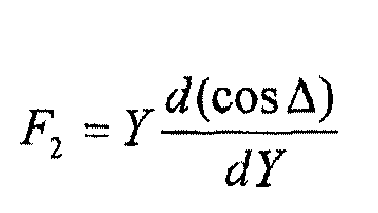
- Procédé de surveillance de stabilité dans un réseau électrique selon la revendication 1, dans lequel
l'angle de phase de charge ϕL est mesuré au niveau du bus dans le réseau électrique et l'angle de phase d'impédance équivalente de source ϕS est estimé avec une erreur inférieure ou égale à +/- 7 degrés. - Procédé de surveillance de stabilité de tension dans un réseau électrique selon la revendication 1, comprenant en outre une étape de détermination d'un point de fonctionnement de tension VOP sur la base d'une caractéristique de fonctionnement du réseau électrique, ledit point de fonctionnement de tension VOP étant calculé en relation avec S, Y, ZS par

où le facteur « H » désigne le rapport (ZSY), auquel le délestage devrait être débuté, et la mise à jour du point de fonctionnement étant effectuée continûment en relation avec les variations d'une différence entre l'angle de phase d'impédance équivalente de source ϕS et l'angle de phase de charge ϕL. - Procédé de maintien de la stabilité dans un réseau électrique, le procédé comprenant un procédé de surveillance de stabilité de tension dans le réseau électrique selon l'une quelconque des revendications 1, 2, 3 et comprenant en outre une étape pour inclure un rétablissement automatique de la charge lorsque la marge de stabilité de tension retourne à des valeurs fixées prédéterminées.
- Appareil pour surveiller la stabilité de tension dans un réseau électrique, l'appareil comprenant :un module d'établissement pour établir une marge de stabilité de réseau électrique dynamique sur la base d'une caractéristique de fonctionnement du réseau électrique,un indicateur pour indiquer que le réseau électrique est devenu instable lorsque la marge de stabilité de réseau électrique dynamique tombe au-dessous d'une valeur prédéterminée,un module de mesure pour mesurer la tension de réseau électrique V,un module d'estimation pour estimer un angle d'impédance équivalente de source ϕS avec une erreur inférieure ou égale à +/- 7 degrés,un module de mesure pour mesurer la valeur de l'angle de phase de charge ϕL au niveau du bus du réseau électrique,un module d'établissement pour établir une différence Δ entre ϕS et ϕL,un module de détermination pour déterminer un état de marge de stabilité de tension en calculant dS/dY par :

où S est une puissance apparente de charge, ZS est une impédance équivalente de source du réseau électrique, Y est une admittance de charge donnée par Y = 1/ZL, ZL étant une impédance de charge connectée à un bus du réseau électrique, et
un module de détermination pour déterminer ladite marge de stabilité de tension en relation avec le rapport entre l'impédance de charge et l'impédance équivalente de source par : où :
où :
où ZL1 et ZL2 sont respectivement les valeurs initiale et finale de l'impédance de charge ZL, et :
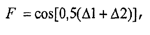
 Δ1 et Δ2 étant respectivement les valeurs initiale et finale de Δ ; l'appareil comprenant en outre des moyens pour débuter un délestage et/ou un rétablissement dynamiques en fonction de ladite marge de stabilité.
 - Appareil selon la revendication 5, comprenant en outre :un module de détermination pour déterminer un point de fonctionnement de tension VOP en relation avec Δ par :
 où le facteur « H » désigne le rapport (ZSY) auquel le délestage devrait être débuté, etun module de correction pour ajuster dynamiquement la différence Δ afin de mettre à jour continûment le point de fonctionnement de tension (VOP).
 - Appareil selon l'une quelconque des revendications 5 et 6, comprenant en outre un module de détermination pour déterminer une quantité de charge à délester si ladite marge de stabilité de tension devient trop faible.
- Appareil selon l'une quelconque des revendications 5 à 7, dans lequel les moyens pour débuter comprennent un module de lancement pour débuter un délestage commandé lorsque ladite marge de stabilité de tension atteint des valeurs prédéterminées et un module de rétablissement pour rétablir automatiquement la charge lorsque ladite marge de stabilité de tension retourne à des valeurs fixées prédéterminées.
Applications Claiming Priority (2)
| Application Number | Priority Date | Filing Date | Title |
|---|---|---|---|
| GB0712749A GB0712749D0 (en) | 2007-07-02 | 2007-07-02 | Method of determining voltage stability margin for load shedding within an electrical power system |
| GB0715760A GB2450762B (en) | 2007-07-02 | 2007-08-14 | Method of determining voltage stability margin for load shedding within an electrical power system |
Publications (3)
| Publication Number | Publication Date |
|---|---|
| EP2079143A2 EP2079143A2 (fr) | 2009-07-15 |
| EP2079143A3 EP2079143A3 (fr) | 2013-04-24 |
| EP2079143B1 true EP2079143B1 (fr) | 2014-07-16 |
Family
ID=38421028
Family Applications (1)
| Application Number | Title | Priority Date | Filing Date |
|---|---|---|---|
| EP20080159312 Not-in-force EP2079143B1 (fr) | 2007-07-02 | 2008-06-30 | Procédé et dispositif pour déterminer la marge de stabilité de tension pour un délestage dans un système d'alimentation électrique |
Country Status (6)
| Country | Link |
|---|---|
| US (1) | US7996116B2 (fr) |
| EP (1) | EP2079143B1 (fr) |
| CN (1) | CN101340090B (fr) |
| CA (1) | CA2636524C (fr) |
| ES (1) | ES2502892T3 (fr) |
| GB (2) | GB0712749D0 (fr) |
Families Citing this family (16)
| Publication number | Priority date | Publication date | Assignee | Title |
|---|---|---|---|---|
| CN101630839B (zh) * | 2009-08-06 | 2012-07-18 | 中国电力科学研究院 | 一种基于功率电流反向的暂态及中长期电压稳定判别方法 |
| WO2011060811A1 (fr) * | 2009-11-17 | 2011-05-26 | Areva T&D Uk Limited | Procédé de réglage d'une tension aux bornes d'une charge |
| US20120277929A1 (en) * | 2009-12-02 | 2012-11-01 | Schneider Electric Energy UK Ltd. | Method of initiating the load shedding within an electrical power system |
| US20130066480A1 (en) * | 2011-09-07 | 2013-03-14 | Quanta Associates, L.P | Real-time monitoring of electric power system voltage stability margins |
| US9234246B1 (en) * | 2012-04-11 | 2016-01-12 | Google Inc. | Decentralized electrical load shedding |
| US9647495B2 (en) | 2012-06-28 | 2017-05-09 | Landis+Gyr Technologies, Llc | Power load control with dynamic capability |
| US9502900B2 (en) * | 2013-05-20 | 2016-11-22 | Quanta Tachnology, LLC | Monitoring voltage stability of a transmission corridor |
| US9291655B2 (en) * | 2013-05-20 | 2016-03-22 | Quanta Technology, Llc | Monitoring voltage stability of a transmission corridor |
| KR101398400B1 (ko) * | 2014-03-06 | 2014-05-27 | 전북대학교산학협력단 | 시변 드룹 기반 풍력발전기의 관성 제어 방법 |
| JP6244255B2 (ja) * | 2014-04-25 | 2017-12-06 | 株式会社日立製作所 | 電圧安定度監視装置および方法 |
| CN104281076B (zh) * | 2014-07-03 | 2017-01-25 | 浙江工业大学 | 蛋白质浓度的控制方法 |
| WO2016067438A1 (fr) * | 2014-10-31 | 2016-05-06 | 株式会社日立製作所 | Dispositif et procédé de commande de stabilisation de système |
| US9971371B2 (en) | 2015-03-17 | 2018-05-15 | Mitsubishi Electric Research Laboratories, Inc. | Method for predicting a voltage collapse in a micro-grid connected to a power distribution network |
| CN105785230B (zh) * | 2016-05-10 | 2018-08-21 | 浙江工业大学 | 一种具有容错性的电压暂降源定位方法 |
| CN117067223B (zh) * | 2023-10-16 | 2024-01-05 | 哈尔滨理工大学 | 一种基于运动稳定性估计的六足机器人自由步态规划方法 |
| CN120385868B (zh) * | 2025-04-14 | 2026-03-17 | 青岛高科电子通信有限公司 | 一种分布式电力数据采集方法、介质及系统 |
Family Cites Families (19)
| Publication number | Priority date | Publication date | Assignee | Title |
|---|---|---|---|---|
| SU699608A1 (ru) * | 1977-06-27 | 1979-11-25 | Казахское Отделение Всесоюзного Ордена Октябрьской Революции Проектно-Изыскательского И Научно-Исследовательского Института Энергетических Систем И Электрических Сетей "Энергосетьпроект" | Способ предотвращени нарушени статической устойчивости линии электропередачи |
| SU741370A1 (ru) * | 1978-02-03 | 1980-06-15 | Производственное Ремонтно-Наладочное Предприятие "Белэнергоремналадка" | Устройство дл аварийной разгрузки узла энергосистемы |
| SU1164824A1 (ru) * | 1983-05-03 | 1985-06-30 | Всесоюзный Заочный Политехнический Институт | Способ управлени беспроводной электропередачей |
| US5642000A (en) * | 1993-05-03 | 1997-06-24 | Cornell Research Foundation, Inc. | Method for preventing power collapse in electric power systems |
| US6249719B1 (en) * | 1998-05-15 | 2001-06-19 | Abb Power T&D Company, Inc. | Applications and methods for voltage instability predictor (VIP) |
| EP1134867B1 (fr) * | 2000-03-10 | 2009-01-14 | ABB Schweiz AG | Dispositif et procédé pour évaluer la stabilité d'un réseau de distibution électrique |
| US20040010350A1 (en) * | 2000-05-31 | 2004-01-15 | Per-Anders Lof | Distributed power generation system protection scheme |
| ATE271274T1 (de) * | 2000-12-01 | 2004-07-15 | Abb Schweiz Ag | Verfahren und vorrichtung zur stabilitätsauswertung eines energieübertragungssystem |
| US7136725B1 (en) * | 2001-06-21 | 2006-11-14 | Paciorek Ronald R | Load shed notification method, product, and apparatus |
| EP1497900A1 (fr) * | 2002-04-22 | 2005-01-19 | The Tokyo Electric Power Co., Inc. | Procede et systeme permettant l'analyse dynamique en ligne d'un systeme electrique |
| US7860702B1 (en) * | 2002-09-18 | 2010-12-28 | Peter B. Evans | Assessing distributed energy resources for the energynet |
| US7149605B2 (en) * | 2003-06-13 | 2006-12-12 | Battelle Memorial Institute | Electrical power distribution control methods, electrical energy demand monitoring methods, and power management devices |
| EP1489715B1 (fr) * | 2003-06-21 | 2009-04-08 | Abb Research Ltd. | Commande d'urgence en temps réel pour des systèmes de puissance |
| SE0400301D0 (sv) * | 2004-02-11 | 2004-02-11 | Stefan Solyom | Power system |
| US7356422B2 (en) * | 2006-04-07 | 2008-04-08 | Schweitzer Engineering Laboratories, Inc. | Apparatus and method for high-speed load shedding in an electrical power system |
| US7508224B2 (en) * | 2006-04-07 | 2009-03-24 | Michael Lamar Williams | Method for measuring stability margin at a node of a polyphase power grid |
| US8126685B2 (en) * | 2006-04-12 | 2012-02-28 | Edsa Micro Corporation | Automatic real-time optimization and intelligent control of electrical power distribution and transmission systems |
| CN100403618C (zh) * | 2006-07-17 | 2008-07-16 | 天津大学 | 电力系统暂态稳定分析与控制方法 |
| US7603203B2 (en) * | 2006-10-09 | 2009-10-13 | Electric Power Research Institute, Inc. | Method for voltage instability load shedding using local measurements |
-
2007
- 2007-07-02 GB GB0712749A patent/GB0712749D0/en not_active Ceased
- 2007-08-14 GB GB0715760A patent/GB2450762B/en not_active Expired - Fee Related
- 2007-12-28 US US11/966,055 patent/US7996116B2/en not_active Expired - Fee Related
-
2008
- 2008-06-30 ES ES08159312.1T patent/ES2502892T3/es active Active
- 2008-06-30 EP EP20080159312 patent/EP2079143B1/fr not_active Not-in-force
- 2008-06-30 CA CA2636524A patent/CA2636524C/fr not_active Expired - Fee Related
- 2008-07-01 CN CN2008101284823A patent/CN101340090B/zh not_active Expired - Fee Related
Also Published As
| Publication number | Publication date |
|---|---|
| US20090009349A1 (en) | 2009-01-08 |
| EP2079143A2 (fr) | 2009-07-15 |
| EP2079143A3 (fr) | 2013-04-24 |
| GB0712749D0 (en) | 2007-08-08 |
| US7996116B2 (en) | 2011-08-09 |
| CA2636524C (fr) | 2017-01-31 |
| CA2636524A1 (fr) | 2009-01-02 |
| CN101340090B (zh) | 2013-08-14 |
| CN101340090A (zh) | 2009-01-07 |
| GB2450762A (en) | 2009-01-07 |
| GB2450762B (en) | 2012-05-16 |
| GB0715760D0 (en) | 2007-09-19 |
| ES2502892T3 (es) | 2014-10-06 |
Similar Documents
| Publication | Publication Date | Title |
|---|---|---|
| US7996116B2 (en) | Method of determining voltage stability margin for load shedding within an electrical power system | |
| US7593823B2 (en) | Method and device for determining state of battery, and battery power supply system therewith | |
| RU2526844C2 (ru) | Способ и устройство дистанционной защиты от замыканий на землю | |
| EP2023154A2 (fr) | Procédé et appareil de détection de l'état de la batterie et procédé de dérivation d'expression | |
| US11467217B2 (en) | Charge capacity calculation device and method for energy storage system | |
| CN108700627B (zh) | 用于测量电力变压器中的功率损耗的方法和系统 | |
| CN101432941B (zh) | 三相输电线路的距离保护中的负荷补偿 | |
| JP7830181B2 (ja) | 電池状態推定装置及び電池状態推定方法 | |
| JP2010279115A (ja) | 電力系統インピーダンス推定装置および電力系統インピーダンス推定方法 | |
| KR20140140863A (ko) | Dc-dc컨버터 전류 추정 방법 | |
| CN105103395B (zh) | 用于检测故障的方法及其电流差动保护系统 | |
| JP4785056B2 (ja) | 充電率推定方法、充電率推定装置及び二次電池電源システム | |
| EP2502122B1 (fr) | Procédé de réglage d'une tension aux bornes d'une charge | |
| JP6897933B2 (ja) | 高圧絶縁監視装置及び高圧絶縁監視方法 | |
| CN114966444A (zh) | 一种soc-ocv的对应关系的校正方法和装置 | |
| CN109270402B (zh) | 一种用于串补线路的变时限距离保护辅助测距方法和系统 | |
| CN120891394B (zh) | 一种基于无人机电池管理系统的电池电量修正方法及系统 | |
| US20120277929A1 (en) | Method of initiating the load shedding within an electrical power system | |
| US12332288B2 (en) | Systems and methods for estimating neutral impedance and detecting faulted neutral connection in an electrical meter | |
| JP2004120918A (ja) | 周波数安定化装置 | |
| US20240159595A1 (en) | Temperature estimation method, temperature estimation program and temperature estimation device | |
| CN114487939A (zh) | 一种电流互感器接线故障的判断方法 | |
| CN121410539A (zh) | 驻车空调的电池电压检测装置、方法、装置、设备及介质 | |
| CN117429292A (zh) | 便携充电桩与电源插座规格的匹配方法和便携充电桩 |
Legal Events
| Date | Code | Title | Description |
|---|---|---|---|
| PUAI | Public reference made under article 153(3) epc to a published international application that has entered the european phase |
Free format text: ORIGINAL CODE: 0009012 |
|
| AK | Designated contracting states |
Kind code of ref document: A2 Designated state(s): AT BE BG CH CY CZ DE DK EE ES FI FR GB GR HR HU IE IS IT LI LT LU LV MC MT NL NO PL PT RO SE SI SK TR |
|
| AX | Request for extension of the european patent |
Extension state: AL BA MK RS |
|
| RAP1 | Party data changed (applicant data changed or rights of an application transferred) |
Owner name: AREVA T&D UK LTD. Owner name: SCHNEIDER ELECTRIC ENERGY UK LTD |
|
| RAP1 | Party data changed (applicant data changed or rights of an application transferred) |
Owner name: ALSTOM GRID UK LIMITED Owner name: SCHNEIDER ELECTRIC ENERGY UK LTD |
|
| RAP1 | Party data changed (applicant data changed or rights of an application transferred) |
Owner name: SCHNEIDER ELECTRIC ENERGY UK LTD Owner name: ALSTOM TECHNOLOGY LTD. |
|
| PUAL | Search report despatched |
Free format text: ORIGINAL CODE: 0009013 |
|
| AK | Designated contracting states |
Kind code of ref document: A3 Designated state(s): AT BE BG CH CY CZ DE DK EE ES FI FR GB GR HR HU IE IS IT LI LT LU LV MC MT NL NO PL PT RO SE SI SK TR |
|
| AX | Request for extension of the european patent |
Extension state: AL BA MK RS |
|
| RIC1 | Information provided on ipc code assigned before grant |
Ipc: H02J 3/24 20060101AFI20130321BHEP |
|
| 17P | Request for examination filed |
Effective date: 20131023 |
|
| RBV | Designated contracting states (corrected) |
Designated state(s): AT BE BG CH CY CZ DE DK EE ES FI FR GB GR HR HU IE IS IT LI LT LU LV MC MT NL NO PL PT RO SE SI SK TR |
|
| AKX | Designation fees paid |
Designated state(s): AT BE BG CH CY CZ DE DK EE ES FI FR GB GR HR HU IE IS IT LI LT LU LV MC MT NL NO PL PT RO SE SI SK TR |
|
| GRAP | Despatch of communication of intention to grant a patent |
Free format text: ORIGINAL CODE: EPIDOSNIGR1 |
|
| INTG | Intention to grant announced |
Effective date: 20140107 |
|
| GRAP | Despatch of communication of intention to grant a patent |
Free format text: ORIGINAL CODE: EPIDOSNIGR1 |
|
| INTG | Intention to grant announced |
Effective date: 20140214 |
|
| GRAS | Grant fee paid |
Free format text: ORIGINAL CODE: EPIDOSNIGR3 |
|
| GRAA | (expected) grant |
Free format text: ORIGINAL CODE: 0009210 |
|
| AK | Designated contracting states |
Kind code of ref document: B1 Designated state(s): AT BE BG CH CY CZ DE DK EE ES FI FR GB GR HR HU IE IS IT LI LT LU LV MC MT NL NO PL PT RO SE SI SK TR |
|
| REG | Reference to a national code |
Ref country code: GB Ref legal event code: FG4D |
|
| REG | Reference to a national code |
Ref country code: CH Ref legal event code: EP |
|
| REG | Reference to a national code |
Ref country code: IE Ref legal event code: FG4D |
|
| REG | Reference to a national code |
Ref country code: AT Ref legal event code: REF Ref document number: 678148 Country of ref document: AT Kind code of ref document: T Effective date: 20140815 |
|
| REG | Reference to a national code |
Ref country code: DE Ref legal event code: R096 Ref document number: 602008033276 Country of ref document: DE Effective date: 20140821 |
|
| REG | Reference to a national code |
Ref country code: ES Ref legal event code: FG2A Ref document number: 2502892 Country of ref document: ES Kind code of ref document: T3 Effective date: 20141006 |
|
| REG | Reference to a national code |
Ref country code: NL Ref legal event code: VDEP Effective date: 20140716 |
|
| REG | Reference to a national code |
Ref country code: AT Ref legal event code: MK05 Ref document number: 678148 Country of ref document: AT Kind code of ref document: T Effective date: 20140716 |
|
| REG | Reference to a national code |
Ref country code: LT Ref legal event code: MG4D |
|
| PG25 | Lapsed in a contracting state [announced via postgrant information from national office to epo] |
Ref country code: LT Free format text: LAPSE BECAUSE OF FAILURE TO SUBMIT A TRANSLATION OF THE DESCRIPTION OR TO PAY THE FEE WITHIN THE PRESCRIBED TIME-LIMIT Effective date: 20140716 Ref country code: FI Free format text: LAPSE BECAUSE OF FAILURE TO SUBMIT A TRANSLATION OF THE DESCRIPTION OR TO PAY THE FEE WITHIN THE PRESCRIBED TIME-LIMIT Effective date: 20140716 Ref country code: PT Free format text: LAPSE BECAUSE OF FAILURE TO SUBMIT A TRANSLATION OF THE DESCRIPTION OR TO PAY THE FEE WITHIN THE PRESCRIBED TIME-LIMIT Effective date: 20141117 Ref country code: SE Free format text: LAPSE BECAUSE OF FAILURE TO SUBMIT A TRANSLATION OF THE DESCRIPTION OR TO PAY THE FEE WITHIN THE PRESCRIBED TIME-LIMIT Effective date: 20140716 Ref country code: BG Free format text: LAPSE BECAUSE OF FAILURE TO SUBMIT A TRANSLATION OF THE DESCRIPTION OR TO PAY THE FEE WITHIN THE PRESCRIBED TIME-LIMIT Effective date: 20141016 Ref country code: GR Free format text: LAPSE BECAUSE OF FAILURE TO SUBMIT A TRANSLATION OF THE DESCRIPTION OR TO PAY THE FEE WITHIN THE PRESCRIBED TIME-LIMIT Effective date: 20141017 Ref country code: NO Free format text: LAPSE BECAUSE OF FAILURE TO SUBMIT A TRANSLATION OF THE DESCRIPTION OR TO PAY THE FEE WITHIN THE PRESCRIBED TIME-LIMIT Effective date: 20141016 |
|
| PG25 | Lapsed in a contracting state [announced via postgrant information from national office to epo] |
Ref country code: CY Free format text: LAPSE BECAUSE OF FAILURE TO SUBMIT A TRANSLATION OF THE DESCRIPTION OR TO PAY THE FEE WITHIN THE PRESCRIBED TIME-LIMIT Effective date: 20140716 Ref country code: AT Free format text: LAPSE BECAUSE OF FAILURE TO SUBMIT A TRANSLATION OF THE DESCRIPTION OR TO PAY THE FEE WITHIN THE PRESCRIBED TIME-LIMIT Effective date: 20140716 Ref country code: NL Free format text: LAPSE BECAUSE OF FAILURE TO SUBMIT A TRANSLATION OF THE DESCRIPTION OR TO PAY THE FEE WITHIN THE PRESCRIBED TIME-LIMIT Effective date: 20140716 Ref country code: LV Free format text: LAPSE BECAUSE OF FAILURE TO SUBMIT A TRANSLATION OF THE DESCRIPTION OR TO PAY THE FEE WITHIN THE PRESCRIBED TIME-LIMIT Effective date: 20140716 Ref country code: PL Free format text: LAPSE BECAUSE OF FAILURE TO SUBMIT A TRANSLATION OF THE DESCRIPTION OR TO PAY THE FEE WITHIN THE PRESCRIBED TIME-LIMIT Effective date: 20140716 Ref country code: IS Free format text: LAPSE BECAUSE OF FAILURE TO SUBMIT A TRANSLATION OF THE DESCRIPTION OR TO PAY THE FEE WITHIN THE PRESCRIBED TIME-LIMIT Effective date: 20141116 |
|
| REG | Reference to a national code |
Ref country code: DE Ref legal event code: R097 Ref document number: 602008033276 Country of ref document: DE |
|
| PG25 | Lapsed in a contracting state [announced via postgrant information from national office to epo] |
Ref country code: RO Free format text: LAPSE BECAUSE OF FAILURE TO SUBMIT A TRANSLATION OF THE DESCRIPTION OR TO PAY THE FEE WITHIN THE PRESCRIBED TIME-LIMIT Effective date: 20140716 Ref country code: EE Free format text: LAPSE BECAUSE OF FAILURE TO SUBMIT A TRANSLATION OF THE DESCRIPTION OR TO PAY THE FEE WITHIN THE PRESCRIBED TIME-LIMIT Effective date: 20140716 Ref country code: SK Free format text: LAPSE BECAUSE OF FAILURE TO SUBMIT A TRANSLATION OF THE DESCRIPTION OR TO PAY THE FEE WITHIN THE PRESCRIBED TIME-LIMIT Effective date: 20140716 Ref country code: DK Free format text: LAPSE BECAUSE OF FAILURE TO SUBMIT A TRANSLATION OF THE DESCRIPTION OR TO PAY THE FEE WITHIN THE PRESCRIBED TIME-LIMIT Effective date: 20140716 Ref country code: IT Free format text: LAPSE BECAUSE OF FAILURE TO SUBMIT A TRANSLATION OF THE DESCRIPTION OR TO PAY THE FEE WITHIN THE PRESCRIBED TIME-LIMIT Effective date: 20140716 Ref country code: CZ Free format text: LAPSE BECAUSE OF FAILURE TO SUBMIT A TRANSLATION OF THE DESCRIPTION OR TO PAY THE FEE WITHIN THE PRESCRIBED TIME-LIMIT Effective date: 20140716 |
|
| PLBE | No opposition filed within time limit |
Free format text: ORIGINAL CODE: 0009261 |
|
| STAA | Information on the status of an ep patent application or granted ep patent |
Free format text: STATUS: NO OPPOSITION FILED WITHIN TIME LIMIT |
|
| REG | Reference to a national code |
Ref country code: FR Ref legal event code: PLFP Year of fee payment: 8 |
|
| 26N | No opposition filed |
Effective date: 20150417 |
|
| PG25 | Lapsed in a contracting state [announced via postgrant information from national office to epo] |
Ref country code: SI Free format text: LAPSE BECAUSE OF FAILURE TO SUBMIT A TRANSLATION OF THE DESCRIPTION OR TO PAY THE FEE WITHIN THE PRESCRIBED TIME-LIMIT Effective date: 20140716 |
|
| PG25 | Lapsed in a contracting state [announced via postgrant information from national office to epo] |
Ref country code: MC Free format text: LAPSE BECAUSE OF FAILURE TO SUBMIT A TRANSLATION OF THE DESCRIPTION OR TO PAY THE FEE WITHIN THE PRESCRIBED TIME-LIMIT Effective date: 20140716 |
|
| REG | Reference to a national code |
Ref country code: CH Ref legal event code: PL |
|
| PG25 | Lapsed in a contracting state [announced via postgrant information from national office to epo] |
Ref country code: LU Free format text: LAPSE BECAUSE OF FAILURE TO SUBMIT A TRANSLATION OF THE DESCRIPTION OR TO PAY THE FEE WITHIN THE PRESCRIBED TIME-LIMIT Effective date: 20150630 |
|
| REG | Reference to a national code |
Ref country code: IE Ref legal event code: MM4A |
|
| PG25 | Lapsed in a contracting state [announced via postgrant information from national office to epo] |
Ref country code: LI Free format text: LAPSE BECAUSE OF NON-PAYMENT OF DUE FEES Effective date: 20150630 Ref country code: IE Free format text: LAPSE BECAUSE OF NON-PAYMENT OF DUE FEES Effective date: 20150630 Ref country code: CH Free format text: LAPSE BECAUSE OF NON-PAYMENT OF DUE FEES Effective date: 20150630 |
|
| REG | Reference to a national code |
Ref country code: FR Ref legal event code: PLFP Year of fee payment: 9 |
|
| PG25 | Lapsed in a contracting state [announced via postgrant information from national office to epo] |
Ref country code: BE Free format text: LAPSE BECAUSE OF FAILURE TO SUBMIT A TRANSLATION OF THE DESCRIPTION OR TO PAY THE FEE WITHIN THE PRESCRIBED TIME-LIMIT Effective date: 20140716 |
|
| PGFP | Annual fee paid to national office [announced via postgrant information from national office to epo] |
Ref country code: GB Payment date: 20160629 Year of fee payment: 9 Ref country code: DE Payment date: 20160531 Year of fee payment: 9 Ref country code: ES Payment date: 20160511 Year of fee payment: 9 |
|
| PGFP | Annual fee paid to national office [announced via postgrant information from national office to epo] |
Ref country code: FR Payment date: 20160530 Year of fee payment: 9 |
|
| PG25 | Lapsed in a contracting state [announced via postgrant information from national office to epo] |
Ref country code: MT Free format text: LAPSE BECAUSE OF FAILURE TO SUBMIT A TRANSLATION OF THE DESCRIPTION OR TO PAY THE FEE WITHIN THE PRESCRIBED TIME-LIMIT Effective date: 20140716 |
|
| PG25 | Lapsed in a contracting state [announced via postgrant information from national office to epo] |
Ref country code: HU Free format text: LAPSE BECAUSE OF FAILURE TO SUBMIT A TRANSLATION OF THE DESCRIPTION OR TO PAY THE FEE WITHIN THE PRESCRIBED TIME-LIMIT; INVALID AB INITIO Effective date: 20080630 |
|
| PG25 | Lapsed in a contracting state [announced via postgrant information from national office to epo] |
Ref country code: HR Free format text: LAPSE BECAUSE OF FAILURE TO SUBMIT A TRANSLATION OF THE DESCRIPTION OR TO PAY THE FEE WITHIN THE PRESCRIBED TIME-LIMIT Effective date: 20140716 |
|
| PG25 | Lapsed in a contracting state [announced via postgrant information from national office to epo] |
Ref country code: TR Free format text: LAPSE BECAUSE OF FAILURE TO SUBMIT A TRANSLATION OF THE DESCRIPTION OR TO PAY THE FEE WITHIN THE PRESCRIBED TIME-LIMIT Effective date: 20140716 |
|
| REG | Reference to a national code |
Ref country code: DE Ref legal event code: R119 Ref document number: 602008033276 Country of ref document: DE |
|
| GBPC | Gb: european patent ceased through non-payment of renewal fee |
Effective date: 20170630 |
|
| REG | Reference to a national code |
Ref country code: FR Ref legal event code: ST Effective date: 20180228 |
|
| PG25 | Lapsed in a contracting state [announced via postgrant information from national office to epo] |
Ref country code: GB Free format text: LAPSE BECAUSE OF NON-PAYMENT OF DUE FEES Effective date: 20170630 Ref country code: DE Free format text: LAPSE BECAUSE OF NON-PAYMENT OF DUE FEES Effective date: 20180103 |
|
| PG25 | Lapsed in a contracting state [announced via postgrant information from national office to epo] |
Ref country code: FR Free format text: LAPSE BECAUSE OF NON-PAYMENT OF DUE FEES Effective date: 20170630 |
|
| REG | Reference to a national code |
Ref country code: ES Ref legal event code: FD2A Effective date: 20181107 |
|
| PG25 | Lapsed in a contracting state [announced via postgrant information from national office to epo] |
Ref country code: ES Free format text: LAPSE BECAUSE OF NON-PAYMENT OF DUE FEES Effective date: 20170701 |