EP2080414B1 - Heizelement - Google Patents
Heizelement Download PDFInfo
- Publication number
- EP2080414B1 EP2080414B1 EP07835299.4A EP07835299A EP2080414B1 EP 2080414 B1 EP2080414 B1 EP 2080414B1 EP 07835299 A EP07835299 A EP 07835299A EP 2080414 B1 EP2080414 B1 EP 2080414B1
- Authority
- EP
- European Patent Office
- Prior art keywords
- ptc
- polymeric compound
- carbon black
- layered
- weight
- Prior art date
- Legal status (The legal status is an assumption and is not a legal conclusion. Google has not performed a legal analysis and makes no representation as to the accuracy of the status listed.)
- Active
Links
Images

Classifications
-
- H—ELECTRICITY
- H05—ELECTRIC TECHNIQUES NOT OTHERWISE PROVIDED FOR
- H05B—ELECTRIC HEATING; ELECTRIC LIGHT SOURCES NOT OTHERWISE PROVIDED FOR; CIRCUIT ARRANGEMENTS FOR ELECTRIC LIGHT SOURCES, IN GENERAL
- H05B3/00—Ohmic-resistance heating
- H05B3/10—Heating elements characterised by the composition or nature of the materials or by the arrangement of the conductor
- H05B3/12—Heating elements characterised by the composition or nature of the materials or by the arrangement of the conductor characterised by the composition or nature of the conductive material
- H05B3/14—Heating elements characterised by the composition or nature of the materials or by the arrangement of the conductor characterised by the composition or nature of the conductive material the material being non-metallic
-
- H—ELECTRICITY
- H05—ELECTRIC TECHNIQUES NOT OTHERWISE PROVIDED FOR
- H05B—ELECTRIC HEATING; ELECTRIC LIGHT SOURCES NOT OTHERWISE PROVIDED FOR; CIRCUIT ARRANGEMENTS FOR ELECTRIC LIGHT SOURCES, IN GENERAL
- H05B3/00—Ohmic-resistance heating
- H05B3/20—Heating elements having extended surface area substantially in a two-dimensional [2D] plane, e.g. plate-heater
- H05B3/22—Heating elements having extended surface area substantially in a two-dimensional [2D] plane, e.g. plate-heater non-flexible
- H05B3/28—Heating elements having extended surface area substantially in a two-dimensional [2D] plane, e.g. plate-heater non-flexible heating conductor embedded in insulating material
-
- H—ELECTRICITY
- H05—ELECTRIC TECHNIQUES NOT OTHERWISE PROVIDED FOR
- H05B—ELECTRIC HEATING; ELECTRIC LIGHT SOURCES NOT OTHERWISE PROVIDED FOR; CIRCUIT ARRANGEMENTS FOR ELECTRIC LIGHT SOURCES, IN GENERAL
- H05B3/00—Ohmic-resistance heating
- H05B3/10—Heating elements characterised by the composition or nature of the materials or by the arrangement of the conductor
- H05B3/12—Heating elements characterised by the composition or nature of the materials or by the arrangement of the conductor characterised by the composition or nature of the conductive material
- H05B3/14—Heating elements characterised by the composition or nature of the materials or by the arrangement of the conductor characterised by the composition or nature of the conductive material the material being non-metallic
- H05B3/146—Conductive polymers, e.g. polyethylene, thermoplastics
-
- H—ELECTRICITY
- H01—ELECTRIC ELEMENTS
- H01C—RESISTORS
- H01C17/00—Apparatus or processes specially adapted for manufacturing resistors
- H01C17/06—Apparatus or processes specially adapted for manufacturing resistors adapted for coating resistive material on a base
- H01C17/065—Apparatus or processes specially adapted for manufacturing resistors adapted for coating resistive material on a base by thick film techniques, e.g. serigraphy
- H01C17/06506—Precursor compositions therefor, e.g. pastes, inks, glass frits or green body
- H01C17/06513—Precursor compositions therefor, e.g. pastes, inks, glass frits or green body characterised by the resistive component
- H01C17/0652—Precursor compositions therefor, e.g. pastes, inks, glass frits or green body characterised by the resistive component containing carbon or carbides
-
- H—ELECTRICITY
- H01—ELECTRIC ELEMENTS
- H01C—RESISTORS
- H01C17/00—Apparatus or processes specially adapted for manufacturing resistors
- H01C17/06—Apparatus or processes specially adapted for manufacturing resistors adapted for coating resistive material on a base
- H01C17/065—Apparatus or processes specially adapted for manufacturing resistors adapted for coating resistive material on a base by thick film techniques, e.g. serigraphy
- H01C17/06506—Precursor compositions therefor, e.g. pastes, inks, glass frits or green body
- H01C17/06573—Precursor compositions therefor, e.g. pastes, inks, glass frits or green body characterised by the permanent binder
- H01C17/06586—Precursor compositions therefor, e.g. pastes, inks, glass frits or green body characterised by the permanent binder composed of organic material
-
- H—ELECTRICITY
- H01—ELECTRIC ELEMENTS
- H01C—RESISTORS
- H01C7/00—Non-adjustable resistors formed as one or more layers or coatings; Non-adjustable resistors made from powdered conducting material or powdered semi-conducting material with or without insulating material
- H01C7/02—Non-adjustable resistors formed as one or more layers or coatings; Non-adjustable resistors made from powdered conducting material or powdered semi-conducting material with or without insulating material having positive temperature coefficient
- H01C7/027—Non-adjustable resistors formed as one or more layers or coatings; Non-adjustable resistors made from powdered conducting material or powdered semi-conducting material with or without insulating material having positive temperature coefficient consisting of conducting or semi-conducting material dispersed in a non-conductive organic material
-
- H—ELECTRICITY
- H05—ELECTRIC TECHNIQUES NOT OTHERWISE PROVIDED FOR
- H05B—ELECTRIC HEATING; ELECTRIC LIGHT SOURCES NOT OTHERWISE PROVIDED FOR; CIRCUIT ARRANGEMENTS FOR ELECTRIC LIGHT SOURCES, IN GENERAL
- H05B3/00—Ohmic-resistance heating
- H05B3/10—Heating elements characterised by the composition or nature of the materials or by the arrangement of the conductor
- H05B3/12—Heating elements characterised by the composition or nature of the materials or by the arrangement of the conductor characterised by the composition or nature of the conductive material
- H05B3/14—Heating elements characterised by the composition or nature of the materials or by the arrangement of the conductor characterised by the composition or nature of the conductive material the material being non-metallic
- H05B3/145—Carbon only, e.g. carbon black, graphite
-
- H—ELECTRICITY
- H01—ELECTRIC ELEMENTS
- H01C—RESISTORS
- H01C7/00—Non-adjustable resistors formed as one or more layers or coatings; Non-adjustable resistors made from powdered conducting material or powdered semi-conducting material with or without insulating material
- H01C7/06—Non-adjustable resistors formed as one or more layers or coatings; Non-adjustable resistors made from powdered conducting material or powdered semi-conducting material with or without insulating material including means to minimise changes in resistance with changes in temperature
-
- H—ELECTRICITY
- H05—ELECTRIC TECHNIQUES NOT OTHERWISE PROVIDED FOR
- H05B—ELECTRIC HEATING; ELECTRIC LIGHT SOURCES NOT OTHERWISE PROVIDED FOR; CIRCUIT ARRANGEMENTS FOR ELECTRIC LIGHT SOURCES, IN GENERAL
- H05B2203/00—Aspects relating to Ohmic resistive heating covered by group H05B3/00
- H05B2203/02—Heaters using heating elements having a positive temperature coefficient
-
- Y—GENERAL TAGGING OF NEW TECHNOLOGICAL DEVELOPMENTS; GENERAL TAGGING OF CROSS-SECTIONAL TECHNOLOGIES SPANNING OVER SEVERAL SECTIONS OF THE IPC; TECHNICAL SUBJECTS COVERED BY FORMER USPC CROSS-REFERENCE ART COLLECTIONS [XRACs] AND DIGESTS
- Y10—TECHNICAL SUBJECTS COVERED BY FORMER USPC
- Y10T—TECHNICAL SUBJECTS COVERED BY FORMER US CLASSIFICATION
- Y10T29/00—Metal working
- Y10T29/49—Method of mechanical manufacture
- Y10T29/49002—Electrical device making
- Y10T29/49082—Resistor making
-
- Y—GENERAL TAGGING OF NEW TECHNOLOGICAL DEVELOPMENTS; GENERAL TAGGING OF CROSS-SECTIONAL TECHNOLOGIES SPANNING OVER SEVERAL SECTIONS OF THE IPC; TECHNICAL SUBJECTS COVERED BY FORMER USPC CROSS-REFERENCE ART COLLECTIONS [XRACs] AND DIGESTS
- Y10—TECHNICAL SUBJECTS COVERED BY FORMER USPC
- Y10T—TECHNICAL SUBJECTS COVERED BY FORMER US CLASSIFICATION
- Y10T29/00—Metal working
- Y10T29/49—Method of mechanical manufacture
- Y10T29/49002—Electrical device making
- Y10T29/49082—Resistor making
- Y10T29/49085—Thermally variable
Definitions
- the invention relates to a PTC (positive temperature coefficient) polymeric compound, a multi-layered, ZPZ (zero-positive-zero temperature coefficient) foil, and a heater.
- US 5,057,674 describes such an element comprising two outer semiconductive layers allegedly having a zero temperature coefficient ("ZTC") separated from one another by a continuous positive temperature coefficient (“PTC”) layer and energized by two parallel electrodes, the first one being in contact with one end of one of the ZTC layers and the second parallel electrode being in contact with the other ZTC layer at its end furthest removed from the first electrode.
- ZTC zero temperature coefficient
- PTC continuous positive temperature coefficient
- the components of the layered structure are such that at room temperature, the resistance in the PTC layer between the ZTC layers is very much less than the resistance in the combined ZTC layers, which in turn is very much less than the resistance in the PTC layer between the electrodes. Further, at control temperature the resistance in the PTC layer between the parallel ZTC layers should be equal to the resistance in the parallel ZTC layers, the geometry being such that at the control temperature where the resistances of the two components are equal, the heat generated per time and unit area (the power densities) are also essentially equal.
- WO 91/17642 describes a heater for passing a VW-1 flame test, wherein the heater is composed of any resistive material, e.g. a conductive polymer composition.
- WO 91/17642 describes a PTC polymeric compound comprising a amorphous thermoplastic matrix mixed with a particulate conductive filler, e.g. carbon black, graphite, metal, metal oxide, or particulate conductive polymer, or a combination of these.
- the PTC layer at room temperature acts as a short circuit between the parallel ZTC layers.
- the resistance between the electrodes in the PTC layer is very high when a voltage is at first applied and the ZTC layers alone develop heat, this is a result of the geometry.
- the resistivity in the PTC layer increases until it is equal to that of the combined ZTC layers. Slightly above this temperature the two ZTC layers act as electrodes and heat is generated uniformly throughout the system, and any further rise in temperature anywhere in the area of the ZTC layers effectively reduces or shuts off the current. In this way the PTC component acts almost only as a control, and the ZTC components perform as the active heating elements.
- polymer matrix is essentially crystalline, the given example being PE and EVA.
- a problem with both this heating element and earlier such elements based on electrically conductive wires threaded through an electrically conductive body is that a small physical damage in the element, such as a hole, will shut off the electrical current and thereby the function of the element.
- PTC materials comprise conductive particles such as carbon black in a crystalline polymer matrix.
- conductive particles such as carbon black in a crystalline polymer matrix.
- the material When the material is heated it expands and the resistivity increases as the gaps between conductive particles and between particle clusters increase. At approximately the polymer melting point a sharp rise in resistivity is obtained, the material "trips", when the polymer softens and melts. This effect is due, not only to increasing distances between particles, but also to the movement of the particles and particle clusters in the melt and the breaking up of particle clusters obtained by the increased energy and movement of the particles within the clusters. On account of these considerable changes within the material, it shows a strong hysteresis effect, and hence the material will not return to its original properties after cooling. Further, as the tripping event is linked to the polymer melting point, it is difficult to adjust the level of the trip temperature.
- US 2002/093007 discloses in an organic PTC thermistor comprising a matrix of at least two high-molecular weight compounds, a low-molecular weight organic compound, and conductive particles having spiky protuberances, a thermoplastic elastomer is contained in the matrix whereby the thermistor is improved in reliability and performance stability.
- WO 89/03162 discloses circuit protection systems which comprise a PTC resistor and a second resistor, e.g. a thick film resistor, which is thermally and electrically connected to the PTC resistor have a break current IB and a hold current IH such that the ratio IB/IH is at most 20.
- Suitable PTC resistors are conductive polymer devices which comprise a PTC element which has been radiation crosslinked under conditions such that the average dose rate is at most 3.0 Mrad/minute or during which no part of the PTC element which is in contact with the electrodes reaches a temperature greater than (Tm-60) DEG C, where Tm is the melting point of the polymeric component of the conductive polymer.
- EP 0435574 discloses a process for producing PTC self-resetting overcurrent protection elements using two different crystalline polymers with an organic peroxide and carbon black.
- the mixture is kneaded at an elevated temperature.
- the two crystalline polymers include different proportions of tertiary hydrogen atoms to carbon atoms, so that the desired PTC characteristics of a highly crystallized polymer can obtain the benefit of greater proportions of tertiary hydrogen in a less highly crystallized polymer.
- a high degree of grafting to carbon black can increase the number of polymer radicals in the crystalline polymer mixture through the decomposition of organic peroxide.
- the resulting mixture tends to disperse the carbon black uniformly throughout the resulting mixture, and to position the carbon black in a three-dimensional matrix in which it is fixed by cross-linking.
- the uniform distribution of the carbon black reduces localized heating and thus minimizes resistance changes following repeated overcurrent conditions.
- An object of the invention is to achieve a positive temperature coefficient, PTC, material suitable for use in a heating element.
- Another object is to achieve a PTC material having a composition adapted to give a desired constant temperature in a heating element.
- a further object is to achieve a heating element which is not sensitive to physical damages and may hold a constant temperature which can be set to fit the intended application.
- a further object is to achieve a very thin heating element that may be cut to fit different applications.
- Another objective is to achieve a heating element that may pass through several heating cycles without essentially changing properties.
- the invention concerns a PTC polymeric compound as claimed in claim 1.
- the invention concerns a multi-layered ZPZ foil as claimed in claim 10.
- the invention concerns a heater as claimed in claim 13.
- the invention concerns according to the first feature a PTC polymeric compound comprising an electrically insulating matrix essentially consisting of an elastomer (elastomeric polymer), first and second electrically conductive particles having different properties with respect to surface energies and electrical conductivities, the material thereby forming a conductive network.
- the first and second electrically conductive particles dispersed in the matrix may consist of carbon blacks having different surface energies and structural morphologies.
- the elastomer in the present PTC polymeric compound is completely amorphous and therefore does not experience the problems present in crystalline polymer PTC materials. Further, the increase in resistivity in the trip temperature regime is mainly due to the properties of the electrically conductive particles, rather than by any increase in volume expansion coefficient of the elastomer nor by any phase change.
- the elastomer is a suitable amorphous polymer having no tendency to crystallize below the desired trip temperature and having a low enough glass transition temperature. It may be selected from the group consisting of chlorinated polyethylene, chlorosulfonated polyethylene, neoprene, nitrile rubber and ethylene-propylene rubber.
- the polymer is preferably based on a siloxane elastomer (often called silicone elastomer) where the polymer backbone may have substituents such as halogenes, for example polyfluorosiloxane. Especially preferred is a polydimethylsiloxane elastomer.
- the elastomeric polymer matrix contains at least two types of electrically conductive particles.
- the conductive particles may comprise two types of carbon blacks where one is a CTC type, i.e. giving rise to essentially a constant temperature coefficient, and the other is a PTC type. Further, fumed silica particles may be used as filler in the polymer matrix.
- the first electrically conductive particles comprise thermal carbon blacks having low surface area and low structure, for example medium thermal carbon blacks
- the second electrically conductive particles comprise furnace carbon blacks having higher structures and higher specific surface areas, such as fast extrusion furnace blacks.
- the thermal carbon black has a mean particle size of at least 200 nm, preferably in the range of 200-580 nm, typically of about 240 nm. It has suitably a specific surface area determined by nitrogen absorption of about 10 m 2 /g.
- the furnace carbon black has a particle size distribution in the range of 20-100 nm, preferably in the range of 40-60 nm and typically in the range of 40-48 nm. It has a specific surface area determined by nitrogen absorption in the range of 30-90 m 2 /g, preferably of about 40 m 2 /g.
- the PTC polymeric compound may comprise 3.6-11 % by weight of the furnace carbon black, 35-55 % by weight, preferably 35-50 % by weight, of the thermal carbon black, at least 2, preferably at least 5 % by weight, and at most 13, preferably at most 10 % by weight of a fumed silica filler and between 35 and 48 % by weight siloxane elastomeric polymer. It may also comprise 0.36-5.76 % by weight of one or more coupling agents, based on the weight of the furnace carbon black.
- the PTC polymeric compound may have a volume resistivity at room temperature in the range of 10 k ⁇ cm to more than 10 M ⁇ cm depending on the composition.
- a PTC polymeric compound to be used in a heating element being a multi -layered device, according to the invention should preferably have a volume resistivity of at least 0.1 M ⁇ cm.
- the trip temperature of the PTC polymeric compound of the invention may be set to a value within the range of 25 to 170°C by adjusting the composition of the PTC polymeric compound.
- the invention concerns a multi-layered ZPZ foil comprising a PTC polymeric compound present between a first essentially planar metal foil and a second essentially planar metal foil, wherein the PTC polymeric compound includes an electrically insulating matrix consisting essentially of an elastomeric amorphous polymer, and first and second electrically conductive particles, dispersed therein, the composite body thereby forming a conductive network extending from the first metal foil to the second metal foil, wherein the first and second electrically conductive particles have different surface energies and electrical conductivities.
- the amorphous polymer comprises a siloxane polymer.
- the composite body comprises a PTC polymeric compound according to the first feature of the invention.
- the multi-layered ZPZ foil may be in the form of an essentially endless web.
- the multi-layered ZPZ foil may also have the size and form suitable for a device according to the third feature of the invention.
- the present invention relates to a multi-layered ZPZ foil wherein the thickness of the composite body may be less than 400 ⁇ m, preferably in the range of 100-300 ⁇ m.
- the multi-layered ZPZ foil has an intermediate layer which may minimize contact resistance.
- the intermediate layer may comprise an electrochemical pre-treatment, wherein the pre-treatment is carried out by electrochemical means.
- the amorphous polymer may be a siloxane polymer as also for the compound and the foil.
- the two-dimensional composite body comprises a PTC polymeric compound present in a multi-layered ZPZ foil of the invention.
- the multi-layered device may further comprise electrodes connected to the electrode layers to facilitate connection to a power supply.
- the volume resistivity of the composite body in the heating element is preferably of an order of magnitude exceeding 0.1 M ⁇ cm.
- the invention further relates to a multi-layered device wherein the thickness of the composite body is less than 400 ⁇ m, preferably in the range of 100-300 ⁇ m.
- the multi-layered device may comprise further layers outside the metal foils, such as polymer layers intended to electrically insulate and protect the metal foils.
- the multi-layered device may comprise an intermediate layer formed at an interface located between the composite body and each of the two metal foils, the intermediate layer comprising an electrochemical pre-treatment.
- the intermediate layer should preferably minimize contact resistance between the composite body and the metal foils.
- the pre-treatment may be carried out by electrochemical means.
- the multi-layered ZPZ foil to be used in the composite body may be in the form of a very long, essentially endless web that may be cut to any size and shape before use.
- the multi-layered device may be used as heating elements in for example heaters for ; motorbike vests, freight containers, wind turbine rotor blades, convection type radiators, aircraft wing leading edge de -icing, pipe tracing, non -resettable fuse temperature hold, wash -room mirrors, toilet seats, food box warm keeping, pet baskets, bath -room towel racks, automotive -and truck external mirror glasses, comfort -and rescue blankets, outdoor LCD panels, radio masts, surgery tables, breathing machine filters, human artificial implants, work shoes, chain-saw -handles and ignitions, outdoor cellular infrastructure amplifier -and rectifier enclosures, water pipe de-icing, road vehicle lead - acid batteries or comfort heated floor -modules.
- the trip temperature of the PTC compound may be adjusted to in between 25 and 170°C, preferably between 40 and 140°C.
- the present invention also relates to a multi -layered device that is a ski lift seat heater having a trip temperature between 40 and 70°C, a traffic mirror heater having a trip temperature between 40 and 70°C, a ski boot heater having a trip temperature between 40 and 70°C, a liquid filled radiator heating element having a trip temperature between 70 and 140°C or a fuel container liquid level sensor having a trip temperature between 40 and 70°C.
- the present invention also relates to a multi -layered device wherein the voltage applied is a DC or AC voltage in the range of about 3-240 V, preferably at about 4.8, 7.2, 12, 24, 48, 60, 120 or 240 V.
- Figs 1a and 1b show an insulated multi -layered ZPZ foil according to the invention which may be used as seat heater.
- the element comprises two 0.012 mm thick copper foils 1, 2 adhering to a 0.136 mm thick layer 3 of conductive PTC polymer sandwiched between the copper foils 1, 2. Outside each copper foil there is an insulating, 0.075 mm thick polyester layer 10, 11.
- Two electrode strips 4, 5 are arranged on the copper foils 1, 2, respectively, forming terminal leads.
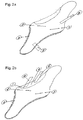
- Figs 2a and 2b show different embodiments of multi -layered ZPZ foils according to the invention to be used in heating elements.
- the size and shape of the two multi -layered ZPZ foils are essentially the same.
- the dashed line on Fig 2a shows the outer perimeter of the multi -layered ZPZ foil in Fig 2b where it differs from the multi -layered ZPZ foil in Fig 2a .
- the dashed line on in Fig 2b shows the outer perimeter of the multi -layered ZPZ foil in Fig 2a where this differs from the multi -layered ZPZ foil in Fig 2b .
- the multi -layered ZPZ foils both comprise a top metal layer 1, a bottom metal layer 2 and an intermediate PTC polymeric compound layer 3.
- the multi -layered ZPZ foil in Fig 2a has a top metal terminal lead 4 and a bottom metal terminal lead 5.
- the multi -layered ZPZ foil in Fig 2b comprises a top metal terminal lead 8 and a bottom metal terminal lead 9 attached to the extended parts 6, 7 of the top metal layer and bottom metal layer, respectively.
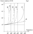
- FIG. 2a and 2b show a diagrammatic representation of the relation between temperature and volume resistivity for a siloxane polymer containing different proportions of carbon black particles and fillers.
- A is a siloxane polymer containing only the CTC powder described in the following examples.
- B) and (D) correspond to the PTC compounds described in the following example 2 and example 1, respectively.
- C), (E) and (F) correspond to other embodiments of the PTC compound of the invention.
- Thermax Stainless Powder N-908 has low surface area and low structure. It is inactive as regards surface chemistry and relatively free of organic functional groups and therefore shows very high chemical and heat resistance. It consists of uniform, soft pellets that are non-pelletizing. The mean particle diameter is 240 nm. It is easily dispersed in the polymer matrix.
- Corax® N 555 is a semi-active carbon black with high structure. It has a particle size distribution between 40 and 48 nm, the arithmetic mean particle diameter being 46.5 nm. The particles form large aggregates visible to the naked eye.
- the powder has a high inherent specific conductivity. It imparts a high viscosity to the polymer matrix.
- the following polymer compound material was prepared, the percentages being based on the weight of the complete composition: 1. PDMS 46.5 % 2. CB MT (CTC powder) 41.2 % 3. CB FEF (PTC powder) 5.2 % 4.Silica 7.2 %
- the silica is a necessary filler to rheologically stabilize the matrix and increase the distance between carbon particles.
- the powder fractions are sieved, the liquid coupling agent is added and the mixture is ultrasonically treated. All components are compounded to a stiff material that is laminated between copper foils.
- the laminate is heat treated at approximately 130°C for 24 hours, where after curing is performed by irradiation with electron-beams into the compounded material, through the metal foils.
- the obtained silicone matrix is nearly completely crosslinked to form one sole molecule.
- the obtained material has a trip temperature of about 45°C.
- a multi -layered ZPZ foil structure of a 0.136 mm thick layer of conductive polymer surrounded by two copper foils of a thickness of 0.012 mm was connected to a power source supplying an AC or DC voltage of 48 V via two electrode strips on the copper foils (see enclosed Fig 1 ).
- the layered structure was cooled to a temperature of -22°C before switching on the power. The temperature rose to +45°C within 17 seconds. The maximum equilibrium temperature was +65°C.
- the following polymer compound material was prepared, the percentages being based on the weight of the complete composition: 1. PDMS 43.2 % 2. CB MT (CTC powder) 50.0 % 3. CB FEF (PTC powder) 4.5 % 4. Silica 2.4 %
- the PTC compound was prepared in the same way as in example 1.
- the obtained composite body has a trip temperature of about 40°C.
- a multi -layered ZPZ foil structure comprising a 0.074 mm thick layer of PTC polymeric compound present in between two copper foils of a thickness of 0.012 mm was connected to a power source supplying an AC or DC voltage of 12 V via two electrode strips on the copper foils.
- the layered structure was cooled to a temperature of -15°C before switching on the power. The temperature rose to 5°C within 30 seconds. The maximum equilibrium temperature was 35°C.
- the trip temperature and maximum equilibrium temperature may be adjusted by changing 1) the proportions of PTC powder and CTC powder, 2) the proportion of silica, 3) the proportion of coupling agent, 4) the irradiation dose and 5) the irradiation temperature.
- the PTC compound of the invention is a completely new type of PTC compound.
- Earlier polymeric PTC materials are based on crystalline polymers or a mixture of crystalline polymers and elastomeric polymers containing electrically conductive particles of PTC type.
- the steep rise in resistance is obtained by a thermal expansion of the polymer matrix followed by a phase change at the melting point.
- the conductive paths through the polymer are disrupted by movement of the particles in the melt and by breaking up of particle agglomerates. As the polymer cools below the melting point not all conductive paths are restored.
- the present PTC polymeric compound comprises a small proportion of 1) small conductive particles (PTC powder) which form large clusters and agglomerates and have a high conductivity, and a large proportion of 2) large conductive particles (CTC powder) not forming clusters and having a relatively low conductivity.
- PTC powder small conductive particles
- CTC powder large conductive particles
- the CTC powder as well as the silica filler are important as to adjusting the rheological properties of the PTC polymeric compound.
- the PTC powder provides conductivity by means of the high inherent specific conductivity of the particles which by large clusters form conductive paths through the polymer.
- the clusters require considerable energy before becoming mobile. However, when finally becoming mobile, they swiftly disrupt the conductive paths and the remaining conductivity is the slowly decreasing basic conductivity formed by the CTC powder. Eventually this disappears at a higher temperature, the equilibrium temperature.
- the trip and maximum temperature of the PTC compound may be adjusted by changing the proportions between PTC powder and CTC powder, a higher proportion of PTC powder generally giving a higher trip temperature. Further, surface treatment of the PTC agglomerates may influence the trip temperature. A stronger bond of the PTC powder to the elastomeric matrix by the use of a higher amount of coupling agent may also increase the trip temperature. However, too much PTC powder and coupling agent may result in loss of the PTC characteristics.
- a through -hole will be burnt across the heater.
- the edges of the metal foils at the through -hole will melt so that the metal edges retract from the hole and the metal layers no longer make contact one to the other.
- the heater will resume its function, except in the damaged part, as the electric current pass in the z-direction between the metal layers.
- a damage will disrupt the electric current permanently and make the heater unserviceable.
Landscapes
- Engineering & Computer Science (AREA)
- Microelectronics & Electronic Packaging (AREA)
- Manufacturing & Machinery (AREA)
- Chemical & Material Sciences (AREA)
- Dispersion Chemistry (AREA)
- Ceramic Engineering (AREA)
- Physics & Mathematics (AREA)
- Electromagnetism (AREA)
- Thermistors And Varistors (AREA)
- Resistance Heating (AREA)
- Compositions Of Macromolecular Compounds (AREA)
- Conductive Materials (AREA)
Claims (12)
- Polymerverbindung mit positivem Temperaturkoeffizienten (PTK-Polymerverbindung) (3), umfassend eine elektrisch isolierende Matrix, im Wesentlichen bestehend aus einem amorphen Siloxanpolymer, und erste und zweite elektrisch leitfähige Teilchen mit unterschiedlichen Oberflächenenergien und elektrischen Leitfähigkeiten, die darin dispergiert sind, wodurch die PTK-Polymerverbindung zu einem leitfähigen Verbundkörper wird, wobei die Verbindung eine Ansprechtemperatur zwischen 25 und 170 °C aufweist und wobei:- die ersten und die zweiten elektrisch leitfähigen Teilchen Ruße mit unterschiedlichen Oberflächenenergien und strukturellen Morphologien umfassen;- die ersten elektrisch leitfähigen Teilchen einen thermischen Ruß umfassen und die zweiten elektrisch leitfähigen Teilchen einen Ofenruß umfassen;- die PTK-Polymerverbindung einen Füllstoff aus pyrogenem Siliciumdioxid umfasst; und- die PTK-Polymerverbindung 3,6 bis 11 Gewichts-% des Ofenrußes, 35 bis 55 Gewichts-% des thermischen Rußes, 2 bis 13 Gewichts-% des Füllstoffes aus pyrogenem Siliciumdioxid und zwischen 35 und 48 Gewichts-% des Siloxan-Elastomerpolymers umfasst.
- PTK-Polymerverbindung nach Anspruch 1, umfassend 0,36 bis 5,76 Gewichts-% Haftvermittler, basiert auf dem Gewicht des Ofenrußes.
- PTK-Polymerverbindung nach Anspruch 2, wobei der Haftvermittler ein lineares Siloxan-Oligomer mit einem mittleren Molekulargewicht von 500 bis 2.500 ist.
- PTK-Polymerverbindung nach einem von Anspruch 1 bis 3, wobei der thermische Ruß eine mittlere Teilchengröße von mindestens 200 nm, vorzugsweise im Bereich von 200 bis 580 nm, typischerweise von etwa 240 nm, aufweist.
- PTK-Polymerverbindung nach einem von Anspruch 1 bis 4, wobei der thermische Ruß eine spezifische Oberfläche, bestimmt mithilfe von Stickstoffabsorption, von etwa 10 m2/g aufweist.
- PTK-Polymerverbindung nach einem von Anspruch 1 bis 5, wobei der Ofenruß eine Teilchengrößenverteilung innerhalb des Bereichs von 20 bis 100 nm, vorzugsweise innerhalb des Bereichs von 40 bis 60 nm und typischerweise innerhalb des Bereichs von 40 bis 48 nm, aufweist.
- PTK-Polymerverbindung nach einem von Anspruch 1 bis 6, wobei der Ofenruß eine spezifische Oberfläche, bestimmt mithilfe von Stickstoffabsorption, von 30 bis 90 m2/g, vorzugsweise von etwa 40 m2/g, aufweist.
- PTK-Polymerverbindung nach einem von Anspruch 1 bis 3 mit einer Ansprechtemperatur zwischen 40 und 140 °C.
- Mehrlagige Folie mit einem Temperaturkoeffizienten von null-positiv-null (NPN-Folie), umfassend einen Verbundkörper (3), der zwischen der ersten (1) und der zweiten (2) im Wesentlichen ebenen Metallfolie vorhanden ist, wobei der Verbundkörper die PTK-Polymerverbindung nach einem von Anspruch 1 bis 8 ist, die ein leitfähiges Netzwerk bildet, das sich von der ersten Metallfolie zur zweiten Metallfolie erstreckt.
- Mehrlagige NPN-Folie nach Anspruch 9, wobei der spezifische Volumenwiderstand des Verbundkörpers von einer Größenordnung ist, die 0,1 MΩcm übersteigt.
- Mehrlagige NPN-Folie nach Anspruch 9 oder 10, umfassend weitere Lagen außerhalb der Metallfolien, wie z.B. Polymerlagen, welche die Metallfolien elektrisch isolieren und schützen sollen.
- Heizvorrichtung, umfassend die mehrlagige Vorrichtung nach einem von Anspruch 9 bis 11 als Heizelement.
Applications Claiming Priority (3)
| Application Number | Priority Date | Filing Date | Title |
|---|---|---|---|
| US82968006P | 2006-10-17 | 2006-10-17 | |
| SE0602172A SE530660C2 (sv) | 2006-10-17 | 2006-10-17 | Värmeelement |
| PCT/SE2007/050714 WO2008048176A1 (en) | 2006-10-17 | 2007-10-05 | Heating element |
Publications (3)
| Publication Number | Publication Date |
|---|---|
| EP2080414A1 EP2080414A1 (de) | 2009-07-22 |
| EP2080414A4 EP2080414A4 (de) | 2014-05-21 |
| EP2080414B1 true EP2080414B1 (de) | 2017-01-18 |
Family
ID=39385814
Family Applications (1)
| Application Number | Title | Priority Date | Filing Date |
|---|---|---|---|
| EP07835299.4A Active EP2080414B1 (de) | 2006-10-17 | 2007-10-05 | Heizelement |
Country Status (10)
| Country | Link |
|---|---|
| US (1) | US8367986B2 (de) |
| EP (1) | EP2080414B1 (de) |
| JP (1) | JP5657889B2 (de) |
| KR (1) | KR101414200B1 (de) |
| CN (1) | CN101523975B (de) |
| CA (1) | CA2665391C (de) |
| DK (1) | DK2080414T3 (de) |
| ES (1) | ES2622067T3 (de) |
| SE (1) | SE530660C2 (de) |
| WO (1) | WO2008048176A1 (de) |
Families Citing this family (27)
| Publication number | Priority date | Publication date | Assignee | Title |
|---|---|---|---|---|
| SE534437C2 (sv) | 2009-09-29 | 2011-08-23 | Conflux Ab | Värmeelement med positiv temperaturkoefficient och deras framställning |
| EP2456003A1 (de) | 2010-11-22 | 2012-05-23 | Saab Automobile Ab | Batteriepack |
| CN102957360A (zh) * | 2011-08-09 | 2013-03-06 | 株式会社村田制作所 | 热敏电阻装置 |
| FR2984418B1 (fr) * | 2011-12-19 | 2014-01-24 | Valeol | Procede de degivrage de structures en materiaux composites, notamment de pales d'une eolienne, composition adaptee et dispositif adapte |
| DE102013215781A1 (de) | 2013-08-09 | 2015-02-12 | Ers Electronic Gmbh | Thermische Abschirmvorrichtung für eine Probecard und entsprechende Probecardanordnung |
| WO2015084241A1 (en) * | 2013-12-02 | 2015-06-11 | Conflux Ab | Compound having exponential temperature dependent electrical resistivity, use of such compound in a self-regulating heating element, self-regulating heating element comprising such compound, and method of forming such compound |
| WO2015084240A1 (en) * | 2013-12-03 | 2015-06-11 | Conflux Ab | Heating arrangement, method for heating, and arrangement and method for controlling an electric current |
| WO2015157106A1 (en) | 2014-04-10 | 2015-10-15 | Illinois Tool Works Inc. | Heater for electric vehicle batteries |
| DE102015014014B4 (de) * | 2015-10-30 | 2017-12-28 | Gentherm Gmbh | Einrichtung zur Temperierung bestimmter Areale und zur Erkennung ihrer personen- und/oder objektbezogenen Belegung sowie Sitz- und/oder Liegevorrichtung mit einer solchen Einrichtung |
| US10350478B2 (en) | 2016-07-06 | 2019-07-16 | Serneke Hybrid Ski Ab | Snow gliding device |
| CN106213586B (zh) * | 2016-08-25 | 2023-06-16 | 上海烟草集团有限责任公司 | 气溶胶生成装置及气溶胶生成方法 |
| US10368394B2 (en) | 2016-09-01 | 2019-07-30 | Hamilton Sundstrand Corporation | PTC heater with autonomous control |
| US11054149B2 (en) * | 2017-05-16 | 2021-07-06 | United States Gypsum Company | Sectionable floor heating system |
| US10775050B2 (en) * | 2017-05-16 | 2020-09-15 | United States Gypsum Company | Sectionable floor heating system |
| SE1751188A1 (en) | 2017-09-25 | 2019-03-12 | Serneke Hybrid Ski Ab | Motor vehicle with snowgliding device |
| CN109561526B (zh) * | 2017-09-26 | 2023-04-25 | 杜邦电子公司 | 加热元件和加热装置 |
| US20190143858A1 (en) * | 2017-11-14 | 2019-05-16 | The Endeavour Group, Inc. | Seat Heater |
| WO2020005151A1 (en) * | 2018-06-25 | 2020-01-02 | Pelen Pte Ltd | Heating device and heating foil |
| US11044789B2 (en) | 2018-10-11 | 2021-06-22 | Goodrich Corporation | Three dimensionally printed heated positive temperature coefficient tubes |
| US11084593B2 (en) | 2018-10-11 | 2021-08-10 | Goodrich Corporation | Additive manufactured heater elements for propeller ice protection |
| CN112312597A (zh) * | 2019-09-12 | 2021-02-02 | 江苏烯泰石墨烯应用技术研究院有限公司 | 高均匀性电加热膜及其制备方法 |
| DE102020127121A1 (de) * | 2019-10-15 | 2021-04-15 | Arte Reverse Engineering GbR (vertretungsberechtigter Gesellschafter Heiko Lantzsch, 98617 Vachdorf) | Heizelement für ein Oberflächenbauteil in einem Kraftfahrzeug |
| US11425797B2 (en) | 2019-10-29 | 2022-08-23 | Rosemount Aerospace Inc. | Air data probe including self-regulating thin film heater |
| IT201900022785A1 (it) * | 2019-12-03 | 2021-06-03 | Irca Spa | Riscaldatore elettrico per riscaldare una sostanza in un autoveicolo |
| CN113080519B (zh) * | 2019-12-23 | 2023-03-14 | 深圳市合元科技有限公司 | 加热器以及包含该加热器的烟具 |
| US11745879B2 (en) | 2020-03-20 | 2023-09-05 | Rosemount Aerospace Inc. | Thin film heater configuration for air data probe |
| US20240064868A1 (en) * | 2020-12-28 | 2024-02-22 | Dongguan Littelfuse Electronics Company Limited | High power pptc heater for low limiting temperature operation |
Citations (1)
| Publication number | Priority date | Publication date | Assignee | Title |
|---|---|---|---|---|
| WO1991017642A1 (en) * | 1990-05-07 | 1991-11-14 | Raychem Corporation | Elongated electrical resistance heater |
Family Cites Families (20)
| Publication number | Priority date | Publication date | Assignee | Title |
|---|---|---|---|---|
| US4330703A (en) * | 1975-08-04 | 1982-05-18 | Raychem Corporation | Layered self-regulating heating article |
| US4654511A (en) * | 1974-09-27 | 1987-03-31 | Raychem Corporation | Layered self-regulating heating article |
| US4177376A (en) | 1974-09-27 | 1979-12-04 | Raychem Corporation | Layered self-regulating heating article |
| US4543474A (en) | 1979-09-24 | 1985-09-24 | Raychem Corporation | Layered self-regulating heating article |
| JPS63170902A (ja) * | 1987-01-09 | 1988-07-14 | 矢崎総業株式会社 | 感温抵抗体 |
| KR890702405A (ko) | 1987-09-30 | 1989-12-23 | 허버트 지. 버카드 | 도전성 폴리머로 구성되는 전기장치 |
| NO880529L (no) | 1988-02-08 | 1989-08-09 | Ramu Int | Selvbegrensede elektrisk varmeelement. |
| JP2810740B2 (ja) | 1989-12-27 | 1998-10-15 | 大東通信機株式会社 | グラフト化法によるptc組成物 |
| JPH0439814A (ja) * | 1990-06-05 | 1992-02-10 | Tokai Carbon Co Ltd | 導電性シートの製造方法 |
| US5250228A (en) * | 1991-11-06 | 1993-10-05 | Raychem Corporation | Conductive polymer composition |
| JPH08102216A (ja) * | 1994-09-30 | 1996-04-16 | Mitsubishi Plastics Ind Ltd | 導電性プラスチツクシート |
| CN1049995C (zh) * | 1994-12-15 | 2000-03-01 | 殷芳卿 | 高分子聚合物正温度系数热敏电阻 |
| US5841111A (en) * | 1996-12-19 | 1998-11-24 | Eaton Corporation | Low resistance electrical interface for current limiting polymers by plasma processing |
| US6104587A (en) * | 1997-07-25 | 2000-08-15 | Banich; Ann | Electrical device comprising a conductive polymer |
| CN1137185C (zh) * | 2000-06-23 | 2004-02-04 | 吉林大学 | 橡胶类聚合物导电复合材料的制备 |
| US6607679B2 (en) | 2001-01-12 | 2003-08-19 | Tdk Corporation | Organic PTC thermistor |
| JP2002241554A (ja) * | 2001-02-13 | 2002-08-28 | Fujikura Ltd | 半導電性混和物 |
| TW543041B (en) * | 2001-12-31 | 2003-07-21 | Polytronics Technology Corp | Manufacturing method of over current protection device |
| JP3882622B2 (ja) * | 2002-01-25 | 2007-02-21 | 松下電器産業株式会社 | Ptc抵抗体 |
| JP2005064090A (ja) * | 2003-08-08 | 2005-03-10 | Nec Tokin Corp | 高分子ptc素子及びその製造方法 |
-
2006
- 2006-10-17 SE SE0602172A patent/SE530660C2/sv unknown
-
2007
- 2007-10-05 US US12/446,187 patent/US8367986B2/en active Active
- 2007-10-05 WO PCT/SE2007/050714 patent/WO2008048176A1/en not_active Ceased
- 2007-10-05 DK DK07835299.4T patent/DK2080414T3/en active
- 2007-10-05 KR KR1020097007706A patent/KR101414200B1/ko active Active
- 2007-10-05 EP EP07835299.4A patent/EP2080414B1/de active Active
- 2007-10-05 CN CN2007800384067A patent/CN101523975B/zh not_active Expired - Fee Related
- 2007-10-05 CA CA2665391A patent/CA2665391C/en active Active
- 2007-10-05 ES ES07835299.4T patent/ES2622067T3/es active Active
- 2007-10-05 JP JP2009533279A patent/JP5657889B2/ja active Active
Patent Citations (1)
| Publication number | Priority date | Publication date | Assignee | Title |
|---|---|---|---|---|
| WO1991017642A1 (en) * | 1990-05-07 | 1991-11-14 | Raychem Corporation | Elongated electrical resistance heater |
Also Published As
| Publication number | Publication date |
|---|---|
| US8367986B2 (en) | 2013-02-05 |
| CN101523975A (zh) | 2009-09-02 |
| EP2080414A1 (de) | 2009-07-22 |
| CA2665391A1 (en) | 2008-04-24 |
| EP2080414A4 (de) | 2014-05-21 |
| JP5657889B2 (ja) | 2015-01-21 |
| CN101523975B (zh) | 2013-11-06 |
| CA2665391C (en) | 2016-08-02 |
| ES2622067T3 (es) | 2017-07-05 |
| KR101414200B1 (ko) | 2014-07-18 |
| SE0602172L (sv) | 2008-04-18 |
| US20100320191A1 (en) | 2010-12-23 |
| WO2008048176A1 (en) | 2008-04-24 |
| JP2010507247A (ja) | 2010-03-04 |
| KR20090080040A (ko) | 2009-07-23 |
| SE530660C2 (sv) | 2008-08-05 |
| DK2080414T3 (en) | 2017-05-01 |
Similar Documents
| Publication | Publication Date | Title |
|---|---|---|
| EP2080414B1 (de) | Heizelement | |
| CA1071281A (en) | Heat-recoverable laminated heater with ptc layer operating above switching temperature | |
| KR970003210B1 (ko) | 전도성 중합체로 이루어지는 전기적 장치 | |
| CA1240407A (en) | Electrical devices comprising cross-linked conductive polymers | |
| CA1143802A (en) | Circuit protection devices comprising ptc elements | |
| US8481898B2 (en) | Self regulating electric heaters | |
| CA1062755A (en) | Layered self-regulating heating article | |
| CA1207467A (en) | Self-regulating electrical heating device | |
| EP0376195A1 (de) | Verfahren zur Herstellung eines selbstregelnden, biegsamen und planen Heizelements | |
| EP2483896B1 (de) | Erhitzungselemente mit positivem temperaturkoeffizienten und ihre herstellung | |
| WO1989007381A1 (en) | Heating element and method for making such a heating element | |
| EP0740841B1 (de) | Wärme-empfindliche beständige verbindung und verfahren zu deren herstellung und verwendung | |
| JP3317895B2 (ja) | 温度自己制御機能ヒータ | |
| JP2852778B2 (ja) | 感熱電気抵抗組成物 | |
| JP3957580B2 (ja) | 自己温度制御型面状ヒータ | |
| GB2033707A (en) | Conductive polymer compositions of an electrical device | |
| CN1624820B (zh) | 一种改进型高分子ptc热敏电阻器及其制造方法 | |
| JP3979188B2 (ja) | 発熱体 | |
| KR790001972B1 (ko) | 적층 자율 조정 가열기 | |
| JPH0737679A (ja) | 正抵抗温度係数を有する発熱体 | |
| JP2004303912A (ja) | Ptc素子 | |
| Sullivan | Processing effects on the performance of PTC composite thermistors | |
| JP2003318006A (ja) | 高分子ptc組成物及び高分子ptc素子 | |
| JP2572429C (de) | ||
| JP2000235903A (ja) | 有機ptc複合材料 |
Legal Events
| Date | Code | Title | Description |
|---|---|---|---|
| PUAI | Public reference made under article 153(3) epc to a published international application that has entered the european phase |
Free format text: ORIGINAL CODE: 0009012 |
|
| 17P | Request for examination filed |
Effective date: 20090325 |
|
| AK | Designated contracting states |
Kind code of ref document: A1 Designated state(s): AT BE BG CH CY CZ DE DK EE ES FI FR GB GR HU IE IS IT LI LT LU LV MC MT NL PL PT RO SE SI SK TR |
|
| DAX | Request for extension of the european patent (deleted) | ||
| A4 | Supplementary search report drawn up and despatched |
Effective date: 20140422 |
|
| RIC1 | Information provided on ipc code assigned before grant |
Ipc: H05B 3/14 20060101AFI20140414BHEP Ipc: H01C 7/02 20060101ALI20140414BHEP |
|
| 17Q | First examination report despatched |
Effective date: 20160517 |
|
| GRAP | Despatch of communication of intention to grant a patent |
Free format text: ORIGINAL CODE: EPIDOSNIGR1 |
|
| INTG | Intention to grant announced |
Effective date: 20161013 |
|
| GRAS | Grant fee paid |
Free format text: ORIGINAL CODE: EPIDOSNIGR3 |
|
| GRAA | (expected) grant |
Free format text: ORIGINAL CODE: 0009210 |
|
| AK | Designated contracting states |
Kind code of ref document: B1 Designated state(s): AT BE BG CH CY CZ DE DK EE ES FI FR GB GR HU IE IS IT LI LT LU LV MC MT NL PL PT RO SE SI SK TR |
|
| REG | Reference to a national code |
Ref country code: GB Ref legal event code: FG4D |
|
| REG | Reference to a national code |
Ref country code: CH Ref legal event code: EP |
|
| REG | Reference to a national code |
Ref country code: AT Ref legal event code: REF Ref document number: 863551 Country of ref document: AT Kind code of ref document: T Effective date: 20170215 |
|
| REG | Reference to a national code |
Ref country code: IE Ref legal event code: FG4D |
|
| REG | Reference to a national code |
Ref country code: DE Ref legal event code: R096 Ref document number: 602007049598 Country of ref document: DE |
|
| REG | Reference to a national code |
Ref country code: NL Ref legal event code: FP |
|
| REG | Reference to a national code |
Ref country code: DK Ref legal event code: T3 Effective date: 20170426 |
|
| REG | Reference to a national code |
Ref country code: SE Ref legal event code: TRGR |
|
| REG | Reference to a national code |
Ref country code: LT Ref legal event code: MG4D |
|
| REG | Reference to a national code |
Ref country code: AT Ref legal event code: MK05 Ref document number: 863551 Country of ref document: AT Kind code of ref document: T Effective date: 20170118 |
|
| REG | Reference to a national code |
Ref country code: ES Ref legal event code: FG2A Ref document number: 2622067 Country of ref document: ES Kind code of ref document: T3 Effective date: 20170705 |
|
| PG25 | Lapsed in a contracting state [announced via postgrant information from national office to epo] |
Ref country code: LT Free format text: LAPSE BECAUSE OF FAILURE TO SUBMIT A TRANSLATION OF THE DESCRIPTION OR TO PAY THE FEE WITHIN THE PRESCRIBED TIME-LIMIT Effective date: 20170118 Ref country code: IS Free format text: LAPSE BECAUSE OF FAILURE TO SUBMIT A TRANSLATION OF THE DESCRIPTION OR TO PAY THE FEE WITHIN THE PRESCRIBED TIME-LIMIT Effective date: 20170518 Ref country code: GR Free format text: LAPSE BECAUSE OF FAILURE TO SUBMIT A TRANSLATION OF THE DESCRIPTION OR TO PAY THE FEE WITHIN THE PRESCRIBED TIME-LIMIT Effective date: 20170419 |
|
| PG25 | Lapsed in a contracting state [announced via postgrant information from national office to epo] |
Ref country code: PT Free format text: LAPSE BECAUSE OF FAILURE TO SUBMIT A TRANSLATION OF THE DESCRIPTION OR TO PAY THE FEE WITHIN THE PRESCRIBED TIME-LIMIT Effective date: 20170518 Ref country code: AT Free format text: LAPSE BECAUSE OF FAILURE TO SUBMIT A TRANSLATION OF THE DESCRIPTION OR TO PAY THE FEE WITHIN THE PRESCRIBED TIME-LIMIT Effective date: 20170118 Ref country code: LV Free format text: LAPSE BECAUSE OF FAILURE TO SUBMIT A TRANSLATION OF THE DESCRIPTION OR TO PAY THE FEE WITHIN THE PRESCRIBED TIME-LIMIT Effective date: 20170118 Ref country code: PL Free format text: LAPSE BECAUSE OF FAILURE TO SUBMIT A TRANSLATION OF THE DESCRIPTION OR TO PAY THE FEE WITHIN THE PRESCRIBED TIME-LIMIT Effective date: 20170118 Ref country code: BG Free format text: LAPSE BECAUSE OF FAILURE TO SUBMIT A TRANSLATION OF THE DESCRIPTION OR TO PAY THE FEE WITHIN THE PRESCRIBED TIME-LIMIT Effective date: 20170418 |
|
| REG | Reference to a national code |
Ref country code: FR Ref legal event code: PLFP Year of fee payment: 11 |
|
| REG | Reference to a national code |
Ref country code: DE Ref legal event code: R097 Ref document number: 602007049598 Country of ref document: DE |
|
| PG25 | Lapsed in a contracting state [announced via postgrant information from national office to epo] |
Ref country code: RO Free format text: LAPSE BECAUSE OF FAILURE TO SUBMIT A TRANSLATION OF THE DESCRIPTION OR TO PAY THE FEE WITHIN THE PRESCRIBED TIME-LIMIT Effective date: 20170118 Ref country code: CZ Free format text: LAPSE BECAUSE OF FAILURE TO SUBMIT A TRANSLATION OF THE DESCRIPTION OR TO PAY THE FEE WITHIN THE PRESCRIBED TIME-LIMIT Effective date: 20170118 Ref country code: SK Free format text: LAPSE BECAUSE OF FAILURE TO SUBMIT A TRANSLATION OF THE DESCRIPTION OR TO PAY THE FEE WITHIN THE PRESCRIBED TIME-LIMIT Effective date: 20170118 Ref country code: EE Free format text: LAPSE BECAUSE OF FAILURE TO SUBMIT A TRANSLATION OF THE DESCRIPTION OR TO PAY THE FEE WITHIN THE PRESCRIBED TIME-LIMIT Effective date: 20170118 |
|
| PLBE | No opposition filed within time limit |
Free format text: ORIGINAL CODE: 0009261 |
|
| STAA | Information on the status of an ep patent application or granted ep patent |
Free format text: STATUS: NO OPPOSITION FILED WITHIN TIME LIMIT |
|
| 26N | No opposition filed |
Effective date: 20171019 |
|
| PG25 | Lapsed in a contracting state [announced via postgrant information from national office to epo] |
Ref country code: SI Free format text: LAPSE BECAUSE OF FAILURE TO SUBMIT A TRANSLATION OF THE DESCRIPTION OR TO PAY THE FEE WITHIN THE PRESCRIBED TIME-LIMIT Effective date: 20170118 |
|
| PG25 | Lapsed in a contracting state [announced via postgrant information from national office to epo] |
Ref country code: MC Free format text: LAPSE BECAUSE OF FAILURE TO SUBMIT A TRANSLATION OF THE DESCRIPTION OR TO PAY THE FEE WITHIN THE PRESCRIBED TIME-LIMIT Effective date: 20170118 |
|
| REG | Reference to a national code |
Ref country code: IE Ref legal event code: MM4A |
|
| PG25 | Lapsed in a contracting state [announced via postgrant information from national office to epo] |
Ref country code: LU Free format text: LAPSE BECAUSE OF NON-PAYMENT OF DUE FEES Effective date: 20171005 |
|
| PG25 | Lapsed in a contracting state [announced via postgrant information from national office to epo] |
Ref country code: MT Free format text: LAPSE BECAUSE OF NON-PAYMENT OF DUE FEES Effective date: 20171005 |
|
| REG | Reference to a national code |
Ref country code: FR Ref legal event code: PLFP Year of fee payment: 12 |
|
| PG25 | Lapsed in a contracting state [announced via postgrant information from national office to epo] |
Ref country code: IE Free format text: LAPSE BECAUSE OF NON-PAYMENT OF DUE FEES Effective date: 20171005 |
|
| PG25 | Lapsed in a contracting state [announced via postgrant information from national office to epo] |
Ref country code: HU Free format text: LAPSE BECAUSE OF FAILURE TO SUBMIT A TRANSLATION OF THE DESCRIPTION OR TO PAY THE FEE WITHIN THE PRESCRIBED TIME-LIMIT; INVALID AB INITIO Effective date: 20071005 |
|
| PG25 | Lapsed in a contracting state [announced via postgrant information from national office to epo] |
Ref country code: CY Free format text: LAPSE BECAUSE OF NON-PAYMENT OF DUE FEES Effective date: 20170118 |
|
| PG25 | Lapsed in a contracting state [announced via postgrant information from national office to epo] |
Ref country code: TR Free format text: LAPSE BECAUSE OF FAILURE TO SUBMIT A TRANSLATION OF THE DESCRIPTION OR TO PAY THE FEE WITHIN THE PRESCRIBED TIME-LIMIT Effective date: 20170118 |
|
| PGFP | Annual fee paid to national office [announced via postgrant information from national office to epo] |
Ref country code: NL Payment date: 20221019 Year of fee payment: 16 |
|
| PGFP | Annual fee paid to national office [announced via postgrant information from national office to epo] |
Ref country code: IT Payment date: 20221026 Year of fee payment: 16 Ref country code: FI Payment date: 20221020 Year of fee payment: 16 Ref country code: ES Payment date: 20221101 Year of fee payment: 16 Ref country code: DK Payment date: 20221014 Year of fee payment: 16 |
|
| PGFP | Annual fee paid to national office [announced via postgrant information from national office to epo] |
Ref country code: CH Payment date: 20221026 Year of fee payment: 16 Ref country code: BE Payment date: 20221017 Year of fee payment: 16 |
|
| REG | Reference to a national code |
Ref country code: CH Ref legal event code: PL |
|
| REG | Reference to a national code |
Ref country code: DK Ref legal event code: EBP Effective date: 20231031 |
|
| REG | Reference to a national code |
Ref country code: NL Ref legal event code: MM Effective date: 20231101 |
|
| REG | Reference to a national code |
Ref country code: BE Ref legal event code: MM Effective date: 20231031 |
|
| PG25 | Lapsed in a contracting state [announced via postgrant information from national office to epo] |
Ref country code: NL Free format text: LAPSE BECAUSE OF NON-PAYMENT OF DUE FEES Effective date: 20231101 Ref country code: CH Free format text: LAPSE BECAUSE OF NON-PAYMENT OF DUE FEES Effective date: 20231031 |
|
| PG25 | Lapsed in a contracting state [announced via postgrant information from national office to epo] |
Ref country code: NL Free format text: LAPSE BECAUSE OF NON-PAYMENT OF DUE FEES Effective date: 20231101 Ref country code: FI Free format text: LAPSE BECAUSE OF NON-PAYMENT OF DUE FEES Effective date: 20231005 Ref country code: CH Free format text: LAPSE BECAUSE OF NON-PAYMENT OF DUE FEES Effective date: 20231031 |
|
| PG25 | Lapsed in a contracting state [announced via postgrant information from national office to epo] |
Ref country code: BE Free format text: LAPSE BECAUSE OF NON-PAYMENT OF DUE FEES Effective date: 20231031 |
|
| PG25 | Lapsed in a contracting state [announced via postgrant information from national office to epo] |
Ref country code: DK Free format text: LAPSE BECAUSE OF NON-PAYMENT OF DUE FEES Effective date: 20231031 |
|
| PG25 | Lapsed in a contracting state [announced via postgrant information from national office to epo] |
Ref country code: DK Free format text: LAPSE BECAUSE OF NON-PAYMENT OF DUE FEES Effective date: 20231031 |
|
| REG | Reference to a national code |
Ref country code: ES Ref legal event code: FD2A Effective date: 20241128 |
|
| PG25 | Lapsed in a contracting state [announced via postgrant information from national office to epo] |
Ref country code: IT Free format text: LAPSE BECAUSE OF NON-PAYMENT OF DUE FEES Effective date: 20231005 |
|
| PG25 | Lapsed in a contracting state [announced via postgrant information from national office to epo] |
Ref country code: IT Free format text: LAPSE BECAUSE OF NON-PAYMENT OF DUE FEES Effective date: 20231005 |
|
| PGFP | Annual fee paid to national office [announced via postgrant information from national office to epo] |
Ref country code: DE Payment date: 20241018 Year of fee payment: 18 |
|
| PGFP | Annual fee paid to national office [announced via postgrant information from national office to epo] |
Ref country code: GB Payment date: 20241017 Year of fee payment: 18 |
|
| PGFP | Annual fee paid to national office [announced via postgrant information from national office to epo] |
Ref country code: FR Payment date: 20241017 Year of fee payment: 18 |
|
| PG25 | Lapsed in a contracting state [announced via postgrant information from national office to epo] |
Ref country code: ES Free format text: LAPSE BECAUSE OF NON-PAYMENT OF DUE FEES Effective date: 20231006 |
|
| PGFP | Annual fee paid to national office [announced via postgrant information from national office to epo] |
Ref country code: SE Payment date: 20241018 Year of fee payment: 18 |
|
| PG25 | Lapsed in a contracting state [announced via postgrant information from national office to epo] |
Ref country code: ES Free format text: LAPSE BECAUSE OF NON-PAYMENT OF DUE FEES Effective date: 20231006 |