EP2080573A2 - Vorrichtung zur Herstellung von Gegenständen aus Metall, insbesondere Leichtmetalllegierungen - Google Patents
Vorrichtung zur Herstellung von Gegenständen aus Metall, insbesondere Leichtmetalllegierungen Download PDFInfo
- Publication number
- EP2080573A2 EP2080573A2 EP08021870A EP08021870A EP2080573A2 EP 2080573 A2 EP2080573 A2 EP 2080573A2 EP 08021870 A EP08021870 A EP 08021870A EP 08021870 A EP08021870 A EP 08021870A EP 2080573 A2 EP2080573 A2 EP 2080573A2
- Authority
- EP
- European Patent Office
- Prior art keywords
- punch
- die
- chamber
- punches
- pressure
- Prior art date
- Legal status (The legal status is an assumption and is not a legal conclusion. Google has not performed a legal analysis and makes no representation as to the accuracy of the status listed.)
- Withdrawn
Links
- 229910052751 metal Inorganic materials 0.000 title claims abstract description 27
- 239000002184 metal Substances 0.000 title claims abstract description 27
- 229910001234 light alloy Inorganic materials 0.000 title claims abstract description 6
- 238000004519 manufacturing process Methods 0.000 title claims abstract description 4
- 238000005242 forging Methods 0.000 claims abstract description 27
- 239000012530 fluid Substances 0.000 claims description 7
- 239000007788 liquid Substances 0.000 claims description 5
- 230000004048 modification Effects 0.000 description 10
- 238000012986 modification Methods 0.000 description 10
- 229910052782 aluminium Inorganic materials 0.000 description 2
- XAGFODPZIPBFFR-UHFFFAOYSA-N aluminium Chemical compound [Al] XAGFODPZIPBFFR-UHFFFAOYSA-N 0.000 description 2
- 238000001816 cooling Methods 0.000 description 2
- 238000000034 method Methods 0.000 description 2
- 230000000630 rising effect Effects 0.000 description 2
- 229910000838 Al alloy Inorganic materials 0.000 description 1
- 229910045601 alloy Inorganic materials 0.000 description 1
- 239000000956 alloy Substances 0.000 description 1
- 230000015572 biosynthetic process Effects 0.000 description 1
- 230000006835 compression Effects 0.000 description 1
- 238000007906 compression Methods 0.000 description 1
- 239000004020 conductor Substances 0.000 description 1
- 230000002950 deficient Effects 0.000 description 1
- 239000007769 metal material Substances 0.000 description 1
- 238000009497 press forging Methods 0.000 description 1
Images

Classifications
-
- B—PERFORMING OPERATIONS; TRANSPORTING
- B22—CASTING; POWDER METALLURGY
- B22D—CASTING OF METALS; CASTING OF OTHER SUBSTANCES BY THE SAME PROCESSES OR DEVICES
- B22D18/00—Pressure casting; Vacuum casting
- B22D18/02—Pressure casting making use of mechanical pressure devices, e.g. cast-forging
-
- B—PERFORMING OPERATIONS; TRANSPORTING
- B22—CASTING; POWDER METALLURGY
- B22D—CASTING OF METALS; CASTING OF OTHER SUBSTANCES BY THE SAME PROCESSES OR DEVICES
- B22D18/00—Pressure casting; Vacuum casting
- B22D18/08—Controlling, supervising, e.g. for safety reasons
-
- B—PERFORMING OPERATIONS; TRANSPORTING
- B22—CASTING; POWDER METALLURGY
- B22D—CASTING OF METALS; CASTING OF OTHER SUBSTANCES BY THE SAME PROCESSES OR DEVICES
- B22D2/00—Arrangement of indicating or measuring devices, e.g. for temperature or viscosity of the fused mass
- B22D2/003—Arrangement of indicating or measuring devices, e.g. for temperature or viscosity of the fused mass for the level of the molten metal
Definitions
- the present invention refers to apparatuses adapted for manufacturing metal articles, in particular of light alloy such as an aluminum alloy, by means of the known method of press-forging by cast in a die (squeeze die cast forging), also known as "liquid forging", by which a molten metal is fed to one or more cavities of a die from a furnace arranged below the die, through a duct associated with the furnace, which metal undergoes a compression during the forging step.
- a die squeeze die cast forging
- liquid forging by which a molten metal is fed to one or more cavities of a die from a furnace arranged below the die, through a duct associated with the furnace, which metal undergoes a compression during the forging step.
- the pressure applied to the metallic material during forging allows to oppose formation of micro-cracks in the forged articles, so that their structure turns out to be more compact and even, and characterized by a higher structural resistance with respect to that obtainable by previously known forging methods.
- the invention relates to an apparatus of the type defined in the preamble of appended claim 1.
- An apparatus of the type mentioned above which is known by EP-A-1 472 027 , comprises a die which may have a plurality of impressions which allow, for example, that a plurality of equal pieces, or pieces different to each other, are manufactured at the same time during a single forging step.
- the upper portion of the die includes a series of movable punches, one for each impression of the die, which are rigidly connected to each other so as to undergo simultaneously a same movement with respect to the upper portion of the die, in order that they apply together a pressure on the metal constituting the articles to be forged.
- the pressure applied to the various articles, or at different zones of a same article, during the forging step may be different from that expected, because of the fact that the various punches are connected to each other so as to move all together with a same stroke, the risk existing that in some forged articles, or at different zones of a same article, micro-cracks may originate, such as to weaken its structure and cause the need to reject them.
- each punch of the die is adapted to be moved in an independent manner with respect to the others punches, so that the expected optimal pressure for the forging step is applied on each article, or on different portions of a same article, the articles obtained have an even quality, and the risk to produce defective articles is excluded a priori.
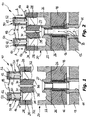
- the apparatus 10 comprises a frame 12 including a furnace (of a type known per se and not shown) adapted to melt a metal fed to it, such as a light alloy, for example an aluminum based alloy.
- the furnace comprises pressure means (also of a type known per se) intended to cause rising of the molten metal along a feeding duct 14 associated to it.
- the duct 14 extends upwards by means of a heated extension 16 crossing a base 18 that supports a die 20 including a lower portion 22, fastened to the base 18 in a known per se manner, and an upper portion 24 which can be separated with respect to the lower portion 22.
- a series of hollow impressions 26 are formed in the portion 22 of the die 20, arranged around an outlet opening 27 of the feeding duct 14.
- Each of the various impressions 26, shown as a non limitative example as generally cup shaped impressions, may pertain to a different article to be forged, or may correspond to different zones of a single article of big dimensions.
- the upper portion 24 of the die 20 is provided with a series of punches 28, the number of which is equal to that of the hollow impressions 26, each of which is slidably and sealingly mounted in a respective cylindrical cavity 30 facing an impression 26.
- One end 32 of each punch 28 facing a respective impression 26 has a shaped surface so as to define, together with the relevant impression 26, a forging cavity the shape of which corresponds to an article, or to a zone of a single article of big dimensions, to be manufactured by means of the apparatus 10.
- the upper portion 24 of the die is usually provided with an appendage 34 which extends towards the outlet opening 27 of the duct 14, in a zone interposed between the punches 28, the perimetral edge 36 of which delimits, together with the edge of the opening 27, in the closed condition of the portions 22 and 24 of the die 20, overflow ports for the molten metal, during the feeding thereof to the impressions 26.
- a sensor device, indicated 38, may be associated to the appendage 34 in a manner known per se, in order to sense that a predetermined level has been reached by the molten metal and to control, as a result, the interruption of the pressurization of the molten metal in the furnace, in order to stop its rising along the duct 14.
- Each punch 28 is fixed at the lower end of a rod 40, the upper end of which is provided with a piston 42 slidably and sealingly mounted in a cylinder 44 adjacent to, and separated from, the cylindrical cavity 30 of the respective punch 28.
- Each cylinder 44 is divided by the piston 42 in two opposite half-chambers, each of which is connected with a respective inlet/outlet duct, indicated 46 and 48, for a service fluid.
- a double-acting actuator 50 for example controlled hydraulically or pneumatically, which allows the movement of the relevant punch 28 to be controlled in a manner independent from the other punches 28.
- a pressure sensor 52 is arranged in the half-chamber of each actuator 50 opposite to the punch 28.
- the sensors 52 of the various actuators 50 are connected by conductors with an electronic control unit (not shown) which receives signals from the sensors 52 and compare them in order to control the movement of each actuator 50 in an independent manner, until each sensor 52 senses that a predetermined forging pressure has been reached, this pressure being the same in each cylinder 44. In this manner, it is possible to assure that each punch 28 applies a pressure equal to that of the others punches 28 on the metal of the article to be forged, and that the pressure applied by the various punches 28 is exactly levelled with respect to a predetermined value.
- the die 20 is open being its portions 22 and 24 separated, and the punches 28 are arranged in a back rest position with respect to the relevant cavities 30.
- the die 20 is closed by controlling the vertical movement of the portion 24 in the direction indicated by arrows A in figure 2 , as a result of driving of a press unit associated with the apparatus 10 in a known per se manner.
- the die 20 is heated and the pressure means of the furnace are operated in order to cause the molten metal to rise along the duct 14, as indicated by arrows B of figure 2 .
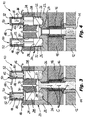
- the molten metal overflows through the ports formed between the edge of the outlet opening 27 and the edge 36 of the appendage 34, until the impressions 26 are filled up according to a dosing predetermined by the configuration of the edge of the opening 27 with respect to the bottom of the impressions 26.
- stopping of the pressure means of the furnace is controlled, so that the molten metal goes down along the duct 14, towards the furnace (arrows C of figure 3 ).
- the electronic control unit of the apparatus 10 controls the driving of the actuators 50 so as to cause advancing of the punches 28 (arrows D of figure 4 ) towards the impressions 26, as a result of feeding the pressurized fluid in the upper half-chambers of the actuators 50.
- the punches 28 apply a compressive force on the molten metal which is present in the impressions 26, which causes both the complete filling of the cavities defined between the impressions 26 and the shaped surfaces of the ends 32 of the punches 28, that is of the cavities which define the shape of the articles or of the article to be forged, and the application of an over-pressure on the metal, which will be usually maintained during the forging step and the successive cooling step.
- each of the actuators 50 being stopped when the value of the pressure sensed by the respective pressure sensor 52 is levelled with the value of pressure predetermined for forging as well as with that sensed by the other sensors 52, in such a manner that all the articles, or all the zones of a same article, undergo the same forging pressure.
- the actuators for driving the punches 28, indicated as a whole by reference 50a are of the single-acting type.
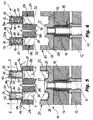
- the actuators 50a comprise a thrust spring 47 arranged in the lower half-chamber of the cylinder 44, that is on the side of the pistons 42 more adjacent to the cylindrical cavities 30, while their upper half-chamber, with the pressure sensors 52 associated to it, can be selectively fed with pressurized fluid through ducts 48 in order to cause the movement of the punches 28 towards the impressions 26 of the lower portion 22 of the die 20.
- the various operational steps of the apparatus remain substantially analogous to those described with reference to the previous modification.
- actuators 50 and 50a described with reference to the previous modifications are of the fluid operated type, they may be replaced, with small changes in the capacity of the skilled person, by electrically driven actuators (not shown), for example of the worm-screw type, in which case the pressure sensors 52 are associated with such electrically driven actuators so as to sense the pressure applied by them during the thrust step of the punches 28.
- the apparatus 10 may comprise a simplified device for driving the punches 28, which does need neither the presence of pressure sensors nor an electronic control unit for managing the operation of the actuator devices.
- the upper portion 24 of the die 20 comprises a unit 56 in which the cylindrical cavities 30 are formed, in which the punches 28 are slidably and sealingly mounted.
- the upper portion of each cavity 30, above the body of the respective punch 28, communicates with the upper portion of the other cavities 30 by means of service ducts 58 (only one of which can be seen in figure 7 ), the volume of the upper portion of the various chambers 30 as well as of the ducts 58 being filled up with a liquid 60, usually oil.
- the punches 28 apply, on the molten metal present in the impressions 26, a pressure which is automatically levelled as a result of the movement of the liquid 60 between the various cavities 30, by virtue of an independent movement of the various punches 28, until each of them applies the same forging pressure on the relevant articles, or at different zones of a same article.
- the various operational steps of the apparatus are substantially analogous to those described with reference to the previous modifications, except for the control step of the movement of the punches 28 which is not provided for, since the actuators, which are replaced by the unit 56, are lacking.
Landscapes
- Engineering & Computer Science (AREA)
- Mechanical Engineering (AREA)
- Forging (AREA)
Applications Claiming Priority (1)
| Application Number | Priority Date | Filing Date | Title |
|---|---|---|---|
| IT000934A ITTO20070934A1 (it) | 2007-12-21 | 2007-12-21 | Apparecchiatura per la fabbricazione di articoli di metallo, in particolare di lega leggera. |
Publications (2)
| Publication Number | Publication Date |
|---|---|
| EP2080573A2 true EP2080573A2 (de) | 2009-07-22 |
| EP2080573A3 EP2080573A3 (de) | 2012-01-25 |
Family
ID=40315922
Family Applications (1)
| Application Number | Title | Priority Date | Filing Date |
|---|---|---|---|
| EP08021870A Withdrawn EP2080573A3 (de) | 2007-12-21 | 2008-12-17 | Vorrichtung zur Herstellung von Gegenständen aus Metall, insbesondere Leichtmetalllegierungen |
Country Status (4)
| Country | Link |
|---|---|
| US (1) | US8210233B2 (de) |
| EP (1) | EP2080573A3 (de) |
| BR (1) | BRPI0805409A2 (de) |
| IT (1) | ITTO20070934A1 (de) |
Families Citing this family (5)
| Publication number | Priority date | Publication date | Assignee | Title |
|---|---|---|---|---|
| JP5527451B1 (ja) * | 2013-03-21 | 2014-06-18 | 宇部興産機械株式会社 | 鋳造装置 |
| KR102457903B1 (ko) * | 2015-05-20 | 2022-10-21 | 알루스트레테지 에스.알.엘. | 경합금 등으로 제조된 물품을 제조하기 위한 설비와 관련된 개선물 |
| CN105903924B (zh) * | 2016-06-14 | 2017-11-28 | 北京交通大学 | 一种复合材料板锤的制备装置及方法 |
| DE102016123491B4 (de) | 2016-12-05 | 2019-12-24 | Schuler Pressen Gmbh | Gießvorrichtung, Presse und Verfahren zum Gießen eines Bauteils |
| IT201900018053A1 (it) * | 2019-10-07 | 2021-04-07 | Euromac Srl | Apparecchiatura e procedimento per la fusione e stampaggio allo stato semi-solido di oggetti in ottone, bronzo, leghe di alluminio, magnesio e leghe leggere e simili. |
Citations (1)
| Publication number | Priority date | Publication date | Assignee | Title |
|---|---|---|---|---|
| EP1472027A1 (de) | 2002-02-07 | 2004-11-03 | Esjotech s.r.l. | Vorrichtung und verfahren zur herstellung von gegenständen aus aluminiumlegierungen oder leichtmetalllegierungen |
Family Cites Families (11)
| Publication number | Priority date | Publication date | Assignee | Title |
|---|---|---|---|---|
| US4049040A (en) * | 1975-08-07 | 1977-09-20 | N L Industries, Inc. | Squeeze casting apparatus and method |
| US4183236A (en) * | 1978-01-30 | 1980-01-15 | Trw Inc. | Method of isothermal forging |
| JPS56102365A (en) * | 1980-01-21 | 1981-08-15 | Honda Motor Co Ltd | Method of filling molten metal in vertical type die casting machine |
| JPS58196159A (ja) * | 1982-05-12 | 1983-11-15 | Honda Motor Co Ltd | 溶湯鍛造用金型 |
| US4991641A (en) * | 1990-05-07 | 1991-02-12 | Electrovert Ltd. | Method of and apparatus for metal casting |
| US5109914A (en) * | 1990-09-04 | 1992-05-05 | Electrovert Ltd. | Injection nozzle for casting metal alloys with low melting temperatures |
| EP0559920B1 (de) * | 1991-10-25 | 1998-07-22 | Toyota Jidosha Kabushiki Kaisha | Vorrichtung zum vakuum-giessen |
| JPH06210426A (ja) * | 1992-03-04 | 1994-08-02 | Mitsubishi Electric Corp | 鋳物の製造方法及び製造装置 |
| JPH0724563A (ja) * | 1993-07-09 | 1995-01-27 | Toyota Motor Corp | 真空鋳造装置および真空鋳造方法 |
| JP2005305466A (ja) * | 2004-04-19 | 2005-11-04 | Art Metal Mfg Co Ltd | 溶湯鍛造装置および溶湯鍛造法 |
| KR101379977B1 (ko) * | 2005-05-19 | 2014-04-01 | 마그나 인터내셔널 인코포레이티드 | 제어된 압력 주조 |
-
2007
- 2007-12-21 IT IT000934A patent/ITTO20070934A1/it unknown
-
2008
- 2008-12-17 EP EP08021870A patent/EP2080573A3/de not_active Withdrawn
- 2008-12-19 BR BRPI0805409-6A patent/BRPI0805409A2/pt not_active Application Discontinuation
- 2008-12-22 US US12/341,870 patent/US8210233B2/en not_active Expired - Fee Related
Patent Citations (1)
| Publication number | Priority date | Publication date | Assignee | Title |
|---|---|---|---|---|
| EP1472027A1 (de) | 2002-02-07 | 2004-11-03 | Esjotech s.r.l. | Vorrichtung und verfahren zur herstellung von gegenständen aus aluminiumlegierungen oder leichtmetalllegierungen |
Also Published As
| Publication number | Publication date |
|---|---|
| US20090158795A1 (en) | 2009-06-25 |
| BRPI0805409A2 (pt) | 2009-08-18 |
| ITTO20070934A1 (it) | 2009-06-22 |
| EP2080573A3 (de) | 2012-01-25 |
| US8210233B2 (en) | 2012-07-03 |
Similar Documents
| Publication | Publication Date | Title |
|---|---|---|
| US6986273B2 (en) | Apparatus and method for opening and closing stacked hydroforming dies | |
| EP2080573A2 (de) | Vorrichtung zur Herstellung von Gegenständen aus Metall, insbesondere Leichtmetalllegierungen | |
| KR100287224B1 (ko) | 스티어링래크바아를제조하는장치 | |
| EP3645192B1 (de) | Verfahren, giessform und vorrichtung zur herstellung eines fahrzeugrads | |
| JPH07112638B2 (ja) | 粉末成形プレスの加圧制御方法 | |
| US10500628B2 (en) | Method and apparatus for reducing cutting impact in a precision blanking press | |
| JP6856123B2 (ja) | 鋳型高さ変更ユニット、抜枠造型機、及び、鋳型高さ変更方法 | |
| EP2210686B1 (de) | Presse zum Heisspressen eines Rohlings mit geschlossenem Gesenk | |
| US20180264765A1 (en) | Press and method for molding an ingot made of thermoplastic or thermosetting material | |
| ITMI20111918A1 (it) | Pressa idraulica verticale adatta allo stampaggio di materiale composito termoplastico o termoindurente. | |
| KR20120083283A (ko) | 스티어링 랙용 단조 금형 장치 | |
| CN115485129B (zh) | 液压机和压制物体的方法 | |
| AU676628B2 (en) | Apparatus for manufacturing steering rack bars | |
| EP1863355B1 (de) | Vorrichtung zur herstellung schalenartig geformter verzehrgüter | |
| JP3657468B2 (ja) | 穴明き製品の成形方法および装置 | |
| JP4523483B2 (ja) | 成型装置 | |
| CN205705385U (zh) | 一种具有人机交互的挤压机 | |
| EP1864776B1 (de) | Hydraulische Presse | |
| CN205705388U (zh) | 一种可多段压力调整的压模系统 | |
| DE102023113473B4 (de) | Hydraulische Umformmaschine zur Werkstückumformung, Hydrauliksteuereinheit und Verfahren zur Steuerung eines Hydraulikzylinders einer hydraulischen Umformmaschine | |
| RU2323801C1 (ru) | Горизонтальная машина для непрерывной разливки и деформации металла | |
| KR20080050667A (ko) | 스틱해제 및 자동 슬라이드 조절기능을 갖는 포징 프레스 | |
| JPH07276100A (ja) | プレス装置 | |
| CA2516115A1 (en) | Apparatus for forming production parts under internal high-pressure conditions | |
| DE102004008157A1 (de) | Gießmaschine zur Herstellung von Gussteilen |
Legal Events
| Date | Code | Title | Description |
|---|---|---|---|
| PUAI | Public reference made under article 153(3) epc to a published international application that has entered the european phase |
Free format text: ORIGINAL CODE: 0009012 |
|
| AK | Designated contracting states |
Kind code of ref document: A2 Designated state(s): AT BE BG CH CY CZ DE DK EE ES FI FR GB GR HR HU IE IS IT LI LT LU LV MC MT NL NO PL PT RO SE SI SK TR |
|
| AX | Request for extension of the european patent |
Extension state: AL BA MK RS |
|
| PUAL | Search report despatched |
Free format text: ORIGINAL CODE: 0009013 |
|
| AK | Designated contracting states |
Kind code of ref document: A3 Designated state(s): AT BE BG CH CY CZ DE DK EE ES FI FR GB GR HR HU IE IS IT LI LT LU LV MC MT NL NO PL PT RO SE SI SK TR |
|
| AX | Request for extension of the european patent |
Extension state: AL BA MK RS |
|
| RIC1 | Information provided on ipc code assigned before grant |
Ipc: B22D 18/08 20060101ALI20111219BHEP Ipc: B22D 18/02 20060101AFI20111219BHEP |
|
| 17P | Request for examination filed |
Effective date: 20120716 |
|
| 17Q | First examination report despatched |
Effective date: 20120814 |
|
| AKX | Designation fees paid |
Designated state(s): AT BE BG CH CY CZ DE DK EE ES FI FR GB GR HR HU IE IS IT LI LT LU LV MC MT NL NO PL PT RO SE SI SK TR |
|
| STAA | Information on the status of an ep patent application or granted ep patent |
Free format text: STATUS: THE APPLICATION IS DEEMED TO BE WITHDRAWN |
|
| 18D | Application deemed to be withdrawn |
Effective date: 20150701 |