EP2080725B1 - Aufzugssystem - Google Patents
Aufzugssystem Download PDFInfo
- Publication number
- EP2080725B1 EP2080725B1 EP20060823009 EP06823009A EP2080725B1 EP 2080725 B1 EP2080725 B1 EP 2080725B1 EP 20060823009 EP20060823009 EP 20060823009 EP 06823009 A EP06823009 A EP 06823009A EP 2080725 B1 EP2080725 B1 EP 2080725B1
- Authority
- EP
- European Patent Office
- Prior art keywords
- light
- car
- operation mode
- hoistway
- emitting device
- Prior art date
- Legal status (The legal status is an assumption and is not a legal conclusion. Google has not performed a legal analysis and makes no representation as to the accuracy of the status listed.)
- Not-in-force
Links
Images

Classifications
-
- B—PERFORMING OPERATIONS; TRANSPORTING
- B66—HOISTING; LIFTING; HAULING
- B66B—ELEVATORS; ESCALATORS OR MOVING WALKWAYS
- B66B5/00—Applications of checking, fault-correcting, or safety devices in elevators
- B66B5/0043—Devices enhancing safety during maintenance
- B66B5/005—Safety of maintenance personnel
- B66B5/0056—Safety of maintenance personnel by preventing crushing
- B66B5/0062—Safety of maintenance personnel by preventing crushing by devices, being operable or not, mounted on the elevator car
-
- B—PERFORMING OPERATIONS; TRANSPORTING
- B66—HOISTING; LIFTING; HAULING
- B66B—ELEVATORS; ESCALATORS OR MOVING WALKWAYS
- B66B5/00—Applications of checking, fault-correcting, or safety devices in elevators
-
- B—PERFORMING OPERATIONS; TRANSPORTING
- B66—HOISTING; LIFTING; HAULING
- B66B—ELEVATORS; ESCALATORS OR MOVING WALKWAYS
- B66B1/00—Control systems of elevators in general
- B66B1/24—Control systems with regulation, i.e. with retroactive action, for influencing travelling speed, acceleration, or deceleration
- B66B1/28—Control systems with regulation, i.e. with retroactive action, for influencing travelling speed, acceleration, or deceleration electrical
Definitions
- the present invention relates to an elevator apparatus including a car which can be raised and lowered in a hoistway.
- a safety device for maintenance of an elevator including a load weight detecting section for detecting a load weight of a car and a car door passage detecting section for detecting passage through an entrance of an opened car door, for detecting whether or not a maintenance person is present on the car based on information from each of the load weight detecting section and the car door passage detecting section.
- the load weight detecting section detects an increase in load weight of the car and, in addition, the car door passage detecting section does not detect the passage, the presence of the maintenance person on the top of the car is detected to inhibit a normal operation of the elevator (see Patent Document 1).
- a safety device provided on a top of an elevator car, including a light-emitting device and a light-receiving device for receiving light from the light-emitting device, the light-emitting device and the light-receiving device being provided on the car, for detecting whether or not a worker is present on the top of the car.
- a light-emitting device and a light-receiving device for receiving light from the light-emitting device, the light-emitting device and the light-receiving device being provided on the car, for detecting whether or not a worker is present on the top of the car.
- two reflecting mirrors are provided on the top of the car.
- One of the reflecting mirrors is located above the light-emitting device, whereas the other reflecting mirror is located above the light-receiving device.
- the light from the light-emitting device is reflected by one of the reflecting mirrors to horizontally travel above a working area on the car. Thereafter, the light is reflected by the other reflecting mirror to reach the light-receiving device.
- the conventional safety device on the top of the elevator car when the reception of the light by the light-receiving device is stopped, the presence of the worker on the top of the car is detected to issue an alarm and stop the car (see Patent Document 2).
- Document JP H 02 169482 discloses an elevator safety system wherein a signal from a transmitter held by a maintenance inspector is received by an antenna on top of the hoistway so the elevator car operation is stopped.
- the present invention has been made in order to solve the problems described above, and has an object to obtain an elevator apparatus capable of preventing a height size of a hoistway from being increased and further ensuring the detection of the presence/absence of a maintenance person on a top of a car.
- An elevator apparatus includes: a car movable in a hoistway; a light-emitting device for emitting light, the light-emitting device being provided to any one of a top of the hoistway and an upper part of the car; a light-receiving device for receiving the light from the light-emitting device, the light-receiving device being provided to another one of the top of the hoistway and the upper part of the car; and a controller capable of switching an operation mode of an elevator between a normal operation mode for moving the car at normal speed and an inspection operation mode for moving the car at a speed lower than the normal speed, the controller performing switching from the normal operation mode to the inspection operation mode when detection of light reception by the light-receiving device is stopped.
- the light-emitting device is provided to any one of the top of the hoistway and the upper part of the car, whereas the light-receiving device is provided to the other one of the top of the hoistway and the upper part of the car.
- the operation mode of the elevator is switched by the controller from the normal operation mode to the inspection operation mode. Therefore, when the maintenance person rides on the top of the car, the light from the light-emitting device is blocked by the maintenance person. As a result, the detection of the reception of light by the light-receiving device can be stopped.
- the detection of the presence/absence of the maintenance person on the top of the car can be further ensured. Moreover, it is no longer necessary to cause the light from the light-emitting device to horizontally pass above the car, and hence the members such as the reflecting mirrors provided on the car for the horizontal passage of the light can be eliminated. Thus, the substantial height size of the car can be reduced, thereby preventing the height size of the hoistway from being increased.
- FIG. 1 is a longitudinal sectional view illustrating an elevator apparatus according to a first embodiment of the present invention.
- FIG. 2 is a sectional view taken along the line II-II illustrated in FIG. 1 .
- a car 2 and a counterweight 3 which can be vertically moved (raised and lowered) are provided in a hoistway 1.
- a landing entrance 5 for bringing the interior of the hoistway 1 and a landing 4 into communication with each other, and a landing door (not shown) for opening and closing the landing entrance 5 are provided.
- a top unit 6 including a plurality of devices placed into a unit is provided at the top of the hoistway 1.
- the top unit 6 includes a horizontally located mounting frame 7, and a hoisting machine (driving device) 8 and a plurality of driven sheaves (not shown) which are provided on the mounting frame 7.
- Each of the hoistingmachine 8 and the driven sheaves is located at an individually determined position (predetermined position).
- the hoisting machine 8 includes a driving sheave (not shown) rotatably driven about a main shaft of the hoisting machine 8.
- the hoisting machine 8 is a thin hoisting machine having a size in a direction along the main shaft (axial direction) smaller than its radial size. Further, the hoisting machine 8 is horizontally located so as to cause the direction of the main shaft to be vertical.
- a plurality of main ropes (not shown) are continuously looped around each of the driving sheave and the driven sheaves.
- the car 2 and the counterweight 3 are suspended by each of the main ropes in the hoistway.
- the car 2 and the counterweight 3 are moved in the hoistway by the rotation of the driving sheave.
- Each of the driven sheaves is rotated with the movement of the car 2 and the counterweight 3.
- multiple (three in this case) light-emitting devices 9a, 9b, and 9c for emitting light are provided.
- the light-emitting devices 9a to 9c are located to be horizontally spaced apart from each other.
- the light-emitting devices 9a to 9c are also embedded in the upper part of the car 2 with their upper parts being exposed.
- the light is emitted upward from each of the light-emitting devices 9a to 9c along a traveling direction of the car 2. Specifically, the light is emitted from each of the light-emitting devices 9a to 9c toward the top of the hoistway 1.
- multiple (three in this case) light-receiving devices 10a, 10b, and 10c for individually receiving the light emitted from each of the light-emitting devices 9a to 9c are provided.
- the light-receiving devices 10a to 10c which are the same in the number as the light-emitting devices 9a to 9c are provided.
- the light-receiving devices 10a to 10c are located to be horizontally spaced apart from each other.
- the light-receiving devices 10a to 10c are arranged in a height direction of the hoistway 1 (traveling direction of car 2) within a dimensional range of the top unit 6.
- the light-receiving devices 10a to 10c are mounted to the hoisting machine 8, and are located inside the mounting frame 7.
- the light-receiving devices 10a to 10c individually detect the presence/absence of the light received respectively from the light-emitting devices 9a to 9c.
- a return switch 11 operable on the top of the car 2 is provided on the car 2.
- a controller 12 for controlling an operation of the elevator is provided on an inner wall of the hoistway 1. Information from each of the light-receiving devices 10a to 10c and the return switch 11 is transmitted to the controller 12.
- the operation of the elevator can be switched by the controller 12 between a normal operation mode for performing a normal operation and an inspection operation mode for performing maintenance and inspection work for the elevator.
- a speed pattern is set by the controller 12 based on a call registration performed by an operation of at least any one of a landing button (not shown) provided at the landing 4 and a destination floor button (not shown) provided in the car 2.
- the car 2 is moved at normal speed according to the thus set speed pattern.
- the car 2 In the inspection mode, the car 2 is moved by an operation of a switch for moving the car at low speed (not shown) provided on the top of the car 2. In the inspection operation mode, the car 2 is moved at a speed lower than the speed (normal speed) of the car 2 in the normal operation mode.
- the controller 12 controls the switching from the normal mode to the inspection operation mode based on the information from each of the light-receiving devices 10a to 10c. Specifically, when the detection of the reception of light by at least any one of the light-receiving devices 10a to 10c is stopped, the controller 12 performs the switching from the normal operation mode to the inspection operation mode. Moreover, after the switching from the normal operation mode to the inspection operation mode, the controller 12 inhibits the switching from the inspection operation mode to the normal operation mode in response to the information from each of the light-receiving devices 10a to 10c.
- the controller 12 also controls the switching from the inspection operation mode to the normal operation mode based on information from the return switch 11. Specifically, only when detecting the operation of the return switch 11, the controller 12 performs the switching from the inspection operation mode to the normal operation mode.
- the operation mode of the elevator is not switched to the normal operation mode unless the return switch 11 is operated even if the reception of light is then detected again by all the light-receiving devices 10a to 10c.
- a maintenance person 13 For the maintenance and inspection of the devices provided in the hoistway 1, a maintenance person 13 sometimes rides on the top of the car 2 to perform the maintenance and inspection work.
- the normal maintenance and inspection are performed for a predetermined device to be maintained, which is installed in the hoistway 1. Therefore, a working position of the maintenance person 13 is determined according to the position of the device to be maintained.
- the predetermined device to be maintained for example, the hoisting machine 8, the controller 12, and the like are given.
- a predetermined working area within which the maintenance person 13 can move for the maintenance and inspection is set.
- a maintenance space for the device to be maintained is ensured.
- the maintenance person 13 performs the maintenance and inspection work for the device to be maintained within the maintenance space.
- the position of the maintenance space for the device to be maintained is set based on the position of the device to be maintained.
- Each of the light-emitting devices 9a to 9c is located with priority within the maintenance space for the device to be maintained. Specifically, the horizontal position of each of the light-emitting devices 9a to 9c is set based on the position of the device to be maintained.
- FIG. 2 illustrates a maintenance space 14 for the controller 12 corresponding to the device to be maintained.
- the maintenance space 14 for the controller 12 is a space on the car 2, which neighbors the controller 12, in a vertical plane of projection of the hoistway 1.
- the light-emitting device 9a corresponding to one of the light-emitting devices 9a to 9c is located within the maintenance space 14 for the controller 12.
- the other light-emitting devices 9b and 9c are located in maintenance spaces for other devices to be maintained (for example, hoisting machine 8 and the like) which are different from the controller 12.
- the operation mode of the elevator is the normal operation mode
- the car 2 is moved at normal speed.
- the reception of the light emitted from each of the light-emitting devices 9a to 9c is detected by the light-receiving devices 10a to 10c, respectively.
- the normal operation mode is kept.
- the maintenance person 13 passes through the landing entrance 5 from the landing 4 to ride on the top of the car 2.
- the light from at least any one of the light-emitting devices 9a to 9c is blocked by the maintenance person 13. Consequently, the detection of the reception of light by at least any one of the light-receiving devices 10a to 10c is stopped.
- the operation mode of the elevator is switched from the normal operation mode to the inspection operation mode by the control of the controller 12.
- the operation of the elevator is switched by the operation of the switch for moving the car at low speed, which is provided on the top of the car 2, to an inspection operation for moving the car 2 at low speed.
- the inspection operation mode is kept as the operation mode of the elevator. Specifically, the operation mode of the elevator is kept regardless of the information from each of the light-receiving devices 10a to 10c. Therefore, the operation mode of the elevator is not switched from the inspection operation mode to the normal operation mode in response to the information from each of the light-receiving devices 10a to 10c.
- the return switch 11 For returning the operation mode of the elevator back to the normal operation mode, the return switch 11 is operated by the maintenance person 13. As a result, the operation mode of the elevator is switched from the inspection operation mode to the normal operation mode.
- the light-emitting devices 9a to 9c are provided in the upper part of the car 2, whereas the light-receiving devices 10a to 10c are provided at the top of the hoistway 1.
- the operation mode of the elevator is switched by the controller 12 from the normal operation mode to the inspection operation mode. Therefore, when the maintenance person 13 rides on the top of the car 2, the light from at least any one of the light-emitting devices 9a to 9c is blocked by the maintenance person 13. In this manner, the detection of the reception of light by at least any one of the light-receiving devices 10a to 10c can be stopped.
- the detection of the presence/absence of the maintenance person 13 on the top of the car 2 can be further ensured.
- the ride of the maintenance person 13 on the top of the car 2 is sufficient to enable the switching of the operation mode to the inspection operation mode.
- the switching from the normal operation mode to the inspection operation mode can be further ensured.
- the multiple light-emitting devices 9a to 9c are located to be horizontally spaced apart from each other, whereas the multiple light-receiving devices 10a to 10c are located to be horizontally spaced apart from each other. Therefore, the presence/absence of the maintenance person 13 can be detected at a plurality of positions on the top of the car 2, thereby further ensuring the detection of the presence/absence of the maintenance person 13 on the top of the car 2.
- the respective horizontal positions of the light-emitting devices 9a to 9c are set based on the positions of the predetermined devices to be maintained, which are provided in the hoistway 1. Therefore, the presence/absence of the maintenance person 13 can be detected at the position with a high possibility of the presence of the maintenance person 13 for the maintenance and inspection. As a result, the detection of the presence/absence of the maintenance person 13 on the top of the car 2 can be further ensured.
- controller 12 performs the switching from the inspection operation mode to the normal operation mode only when the operation of the return switch 11 provided on the top of the car 2 is detected, and hence the inspection operation mode can be prevented from being accidentally switched to the normal operation mode against the will of the maintenance person 13.
- the top unit 6 including the hoisting machine 8 is provided at the top of the hoistway 1.
- the light-receiving devices 10a to 10c are provided within the range of the top unit 6 in the height direction of the hoistway 1. Therefore, each of the light-receiving devices 10a to 10c can be prevented from projecting downward beyond the top unit 6. As a result, the height size of the hoistway 1 can be further prevented from being increased.
- each of the light-emitting devices 9a to 9c is provided in the upper part of the car 2 and each of the light-receiving devices 10a to 10c is provided at the top of the hoistway 1 in the above-mentioned example, each of the light-receiving devices 10a to 10c may be provided in the upper part of the car 2 and the light-emitting devices 9a to 9c may be provided at the top of the hoistway 1.
- each of the light-emitting devices 9a to 9c may also be replaced by a transmitter for infrared communication, whereas each of the light-receiving devices 10a to 10c may be replaced by a receiver for infrared communication.
- the light from each of the light-emitting devices 9a to 9c is made to be an infrared ray, and the control information transmitted between the car 2 and the controller 12 may be contained in the light from each of the light-emitting devices 9a to 9c. In this case, the control information is transmitted from each of the light-emitting devices 9a to 9c to each of the light-receiving devices 10a to 10c.
- control information when each of the light-emitting devices 9a to 9c is provided in the upper part of the car 2, information of the call registration or the like is given, for example.
- information of the position of the car 2 or the like is given, for example.
- control cable travelling cable
- the control information is contained in the light from each of the light-emitting devices 9a to 9c.
- the control cable can be partially eliminated.
- the control cable can be reduced in weight, thereby lowering the cost of the control cable.
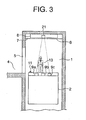
- FIG. 3 is a longitudinal sectional view illustrating the elevator apparatus according to a second embodiment of the present invention.
- a CCD camera (image recognition device) 21 is provided as the light-receiving device.
- the CCD camera 21 is capable of detecting the light from each of the light-emitting devices 9a to 9c as an image. In this manner, the light from each of the light-emitting devices 9a to 9c is detected by the same CCD camera 21.
- the image information detected by the CCD camera 21 is transmitted to the controller 12.
- the CCD camera 21 is provided to the hoisting machine 8.
- the controller 12 controls the switching from the normal operation mode to the inspection operation mode based on the image information from the CCD camera 21. Specifically, the controller 12 compares the image information from the CCD camera 21 and set reference information, which is preset, to control the switching from the normal operation mode to the inspection operation mode.
- the set reference information is image information when the light from the respective light-emitting devices 9a to 9c are all detected by the CCD camera 21 (specifically, the light from each of the light-emitting devices 9a to 9c to the CCD camera 21 is not blocked).
- the controller 12 When the image information from the CCD camera 21 does not match the set reference information to result in the stop of the detection of the light from at least any one of the light-emitting devices 9a to 9c, the controller 12 performs the switching from the normal operation mode to the inspection operation mode.
- the other structure is the same as that described in the first embodiment.
- the CCD camera 21 capable of detecting as the image the light from each of the light-emitting devices 9a to 9c is used as the light-receiving device. Therefore, the detection of the light from each of the light-emitting devices 9a to 9c can be further ensured, thereby further ensuring the detection of the presence/absence of the maintenance person 13 on the top of the car 2.
- each of the light-emitting devices 9a to 9c is provided in the upper part of the car 2 and the CCD camera 21 is provided at the top of the hoistway 1.
- the CCD camera 21 may be provided in the upper part of the car 2, whereas each of the light-emitting devices 9a to 9c may be provided at the top of the hoistway 1.
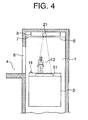
- FIG. 4 is a longitudinal sectional view illustrating the elevator apparatus according to a third embodiment of the present invention.
- a light-emitting device 31 is provided in the upper part of the car 2.
- the light-emitting device 31 includes a line light source for linearly emitting light to the CCD camera 21.
- the line light source of the light-emitting device 31 extends horizontally.
- a plurality of LEDs arranged in a linearly continuous manner or the like can be given.
- the line light source may be either linear or curvilinear.
- the CCD camera 21 is capable of detecting the light from the light-emitting device 31 as the image.
- the image information detected by the CCD camera 21 is transmitted to the controller 12.
- the controller 12 compares the image information from the CCD camera 21 and the set reference information, which is preset, to control the switching from the normal operation mode to the inspection operation mode.
- the set reference information is image information when the light from all parts of the line light source (specifically, the entire line light source) of the light-emitting device 31 is detected by the CCD camera 21 (specifically, the light from the entire line light source to the CCD camera 21 is not blocked).
- the controller 12 performs the switching from the normal operation mode to the inspection operation mode.
- the other structure is the same as that described in the second embodiment.
- the light-emitting device 31 has the line light source for linearly emitting the light to the CCD camera 21. Therefore, the range of light emission by the light-emitting device 31 can be continuous . As a result, the detection of the presence/absence of the maintenance person 31 on the top of the car 2 can be further ensured.
- the light source of the light-emitting device 31 is the line light source.
- a surface light source for emitting light in a planar manner to the CCD camera 21 may also be the light source of the light-emitting device.
- the light-emitting device is provided within a predetermined range of the upper part of the car 2.
- the image information when the light from all the parts of the surface light source (specifically, the entire surface light source) of the light-emitting device is detected by the CCD camera 21 is set as the set reference information. In this manner, the range where the light emission by the light-emitting device is continuous can be further increased, thereby further ensuring the detection of the presence/absence of the maintenance person 13 on the top of the car 2.
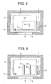
- FIG. 5 is a horizontal sectional view illustrating the elevator apparatus according to a fourth embodiment of the present invention.
- a light-emitting device 41 including a line light source is horizontally provided in the upper part of the car 2.
- the light-emitting device 41 is provided on the side of the predetermined working area within the area of the car 2 to be closer to the landing entrance 5 in the vertical plane of projection of the hoistway 1.
- the line light source of the light-emitting device 41 is arranged along a width direction of the landing entrance 5. Further, the line light source of the light-emitting device 41 is arranged over the entire landing entrance 5 in the width direction of the landing entrance 5.
- a length of the line light source of the light-emitting device 41 is set longer than a width dimension of the landing entrance 5.
- the line light source of the light-emitting device 41 is provided between the landing entrance 5 and the predetermined working area on the car 2 in the vertical plane of projection of the hoistway 1.
- the other structure is the same as that described in the third embodiment.
- the line light source of the light-emitting device 41 is provided between the landing entrance 5 and the predetermined working area on the car 2 in the vertical plane of projection of the hoistway 1. Therefore, the maintenance person 13 moving between the landing entrance 5 and the top of the car 2 can be detected. As a result, the detection of the presence/absence of the maintenance person 13 on the top of the car 2 can be further ensured.
- FIG. 6 is a horizontal sectional view illustrating the elevator apparatus according to a fifth embodiment of the present invention.
- multiple (two in this example) light-emitting devices 51 and 52 are provided in the upper part of the car 2.
- Each of the light-emitting devices 51 and 52 includes a line light source for linearly emitting the light to the CCD camera 21.
- Each of the light-emitting devices 51 and 52 is provided within the maintenance space 14 for the controller 12. Further, the line light source of each of the light-emitting devices 51 and 52 is provided along a width direction of the controller 12. Specifically, the horizontal position of each of the light-emitting devices 51 and 52 is set based on the position of the controller 12 corresponding to the device to be maintained.
- the light-emitting devices 51 and 52 are provided to be horizontally spaced apart from each other. Though not shown, the light-emitting devices 51 and 52 are also provided within the maintenance space for the device to be maintained which is different from the controller 12. The other structure is the same as that described in the fourth embodiment.
- each of the plurality of the light-emitting devices 51 and 52 includes the line light source, and the horizontal position of each of the light-emitting devices 51 and 52 is set based on the position of the controller 12. Therefore, the presence/absence of the maintenance person 13 can be detected at the position with a high possibility of the presence of the maintenance person 13 during the maintenance and inspection. As a result, the detection of the presence/absence of the maintenance person 13 on the top of the car 2 can be further ensured. Moreover, the range of the light emission by the light-emitting devices 51 and 52 can be made continuous , and hence the detection of the presence/absence of the maintenance person 13 on the top of the car 2 can be further ensured.
- the light source of each of the light-emitting devices 51 and 52 is the line light source in the example described above
- the surface light source for emitting the light in a planar manner to the CCD camera 21 may be used as the light source of the light-emitting device.
- the image information when the light from all the parts of the surface light source of the light-emitting device (specifically, entire surface light source) is detected by the CCD camera 21 is set as the set reference information for the controller 12. In this manner, the range where the light emission by the light-emitting devices is continuous can be further increased, thereby further ensuring the detection of the presence/absence of the maintenance person 13 on the top of the car 2.
- the number of the CCD camera 21 is one in the second to fifth embodiments, the number of the CCD camera 21 may also be plural.
Landscapes
- Engineering & Computer Science (AREA)
- Automation & Control Theory (AREA)
- Indicating And Signalling Devices For Elevators (AREA)
- Maintenance And Inspection Apparatuses For Elevators (AREA)
- Cage And Drive Apparatuses For Elevators (AREA)
Claims (10)
- Aufzugsvorrichtung mit:einer Kabine (2), die in einem Aufzugsschacht (1) bewegbar ist, gekennzeichnet durcheine Lichtemissionseinrichtung (9a, 9b, 9c) zur Emission von Licht, wobei die Lichtemissionseinrichtung (9a, 9b, 9c) entweder an einer Oberseite des Aufzugsschachts (1) oder einem oberen Teil der Kabine (2) angeordnet ist;eine Lichtempfangseinrichtung (10a, 10b, 10c) zum Empfangen des Lichts von der Lichtemissionseinrichtung (9a, 9b, 9c), wobei die Lichtempfangseinrichtung (10a, 10b, 10c) an dem jeweils anderen Element aus der Oberseite des Aufzugsschachts (1) und dem oberen Teil der Kabine (2) angeordnet ist; undeine Steuereinrichtung (12), die geeignet ist, einen Betriebsmodus des Aufzugs zwischen einem Normalbetriebsmodus zur Bewegung der Kabine (2) mit Normalgeschwindigkeit und einem Inspektionsbetriebsmodus zur Bewegung der Kabine (2) mit einer geringeren Geschwindigkeit als die Normalgeschwindigkeit umzuschalten, wobei die Steuereinrichtung (12) das Umschalten von dem Normalbetriebsmodus zum Inspektionsbetriebsmodus ausführt, wenn die Erfassung des Lichtempfangs durch die Lichtempfangseinrichtung (10a, 10b, 10c) gestoppt ist.
- Aufzugsvorrichtung nach Anspruch 1,
bei der mehrere der Lichtemissionseinrichtungen (9a, 9b, 9c) derart angeordnet sind, dass sie horizontal voneinander beabstandet sind, und mehrere der Lichtempfangseinrichtungen (10a, 10b, 10c) derart angeordnet sind, dass sie horizontal voneinander beabstandet sind, und
die Steuereinrichtung (12) das Umschalten vom Normalbetriebsmodus in den Inspektionsbetriebsmodus ausführt, wenn die Erfassung des Lichtempfangs von zumindest einer der Lichtempfangseinrichtungen (10a, 10b, 10c) gestoppt ist. - Aufzugsvorrichtung nach Anspruch 1, bei der eine Horizontalposition der Lichtemissionseinrichtung (9a, 9b, 9c) oder der Lichtempfangseinrichtung (10a, 10b, 10c), die an dem oberen Teil der Kabine (2) angeordnet ist, basierend auf einer Position einer vorbestimmten, zu wartenden Einrichtung eingestellt ist, welche in dem Aufzugsschacht (1) angeordnet ist.
- Aufzugsvorrichtung nach Anspruch 1, ferner mit einem Umkehrschalter (11), der an der Kabine (2) angebracht ist, wobei der Umkehrschalter (11) an der Kabine (2) betätigbar ist,
wobei die Steuereinrichtung (12) das Umschalten von dem Inspektionsbetriebsmodus zum Normalbetriebsmodus nur dann ausführt, wenn die Steuereinrichtung (12) eine Betätigung des Umkehrschalters (11) erfasst. - Aufzugsvorrichtung nach Anspruch 1, ferner mit einer oberseitigen Einheit (6) mit einer Antriebseinrichtung (8) zum Anheben und Ablassen der Kabine (2), wobei die oberseitige Einheit (6) an der Oberseite des Aufzugsschachts (1) angeordnet ist,
wobei die Lichtemissionseinrichtung (9a, 9b, 9c) oder die Lichtempfangseinrichtung (10a, 10b, 10c), die an der Oberseite des Aufzugsschachts (1) angeordnet ist, innerhalb eines Bereichs der oberseitigen Einheit (6) in einer Höhenrichtung des Aufzugsschachts (1) angeordnet ist. - Aufzugsvorrichtung nach Anspruch 1, bei der das Licht von der Lichtemissionseinrichtung (9a, 9b, 9c) Steuerungsinformation enthält, die zwischen der Kabine (2) und der Steuereinrichtung (12) zu übertragen ist.
- Aufzugsvorrichtung nach Anspruch 1, bei der die Lichtempfangseinrichtung (21) eine Bilderkennungseinrichtung ist, die in der Lage ist, das Licht von der Lichtemissionseinrichtung (9a, 9b, 9c) als ein Bild zu erfassen.
- Aufzugsvorrichtung nach Anspruch 7, bei der die Lichtemissionseinrichtung (31) eine Linien-Lichtquelle zur linearen Lichtemission an die Lichtempfangseinrichtung (21) aufweist.
- Aufzugsvorrichtung nach Anspruch 7, bei der die Lichtemissionseinrichtung eine Flächenlichtquelle zur Lichtemission an die Lichtempfangseinrichtung auf eine ebene Weise aufweist.
- Aufzugsvorrichtung nach Anspruch 8 oder 9, bei der
die Lichtemissionseinrichtung (41) an dem oberen Teil der Kabine (2) angeordnet ist, und die Lichtempfangseinrichtung (21) an der Oberseite des Aufzugsschachts (1) angeordnet ist, und
die Lichtemissionseinrichtung (41) zwischen einem Stockwerkflur-Eingang (5), welcher dazu dient, den Aufzugsschacht (1) und einen Stockwerkflur (4) miteinander in Verbindung zu bringen, und einem vorbestimmten Arbeitsbereich auf der Kabine (2) in einer vertikalen Projektionsebene des Aufzugsschachts (1) angeordnet ist.
Applications Claiming Priority (1)
| Application Number | Priority Date | Filing Date | Title |
|---|---|---|---|
| PCT/JP2006/322095 WO2008056398A1 (fr) | 2006-11-06 | 2006-11-06 | Système pour un ascenseur |
Publications (3)
| Publication Number | Publication Date |
|---|---|
| EP2080725A1 EP2080725A1 (de) | 2009-07-22 |
| EP2080725A4 EP2080725A4 (de) | 2013-07-10 |
| EP2080725B1 true EP2080725B1 (de) | 2015-05-20 |
Family
ID=39364227
Family Applications (1)
| Application Number | Title | Priority Date | Filing Date |
|---|---|---|---|
| EP20060823009 Not-in-force EP2080725B1 (de) | 2006-11-06 | 2006-11-06 | Aufzugssystem |
Country Status (5)
| Country | Link |
|---|---|
| EP (1) | EP2080725B1 (de) |
| JP (1) | JP4885975B2 (de) |
| KR (1) | KR100975475B1 (de) |
| CN (1) | CN101535161B (de) |
| WO (1) | WO2008056398A1 (de) |
Cited By (2)
| Publication number | Priority date | Publication date | Assignee | Title |
|---|---|---|---|---|
| US10526168B2 (en) | 2015-10-22 | 2020-01-07 | Otis Elevator Company | Service alarm device for warning if an elevator safety device is not activated |
| EP4717653A1 (de) * | 2024-09-25 | 2026-04-01 | Otis Elevator Company | Zulässigen arbeitsbereich in einem virtuellen sicherheitsnetzsystem |
Families Citing this family (13)
| Publication number | Priority date | Publication date | Assignee | Title |
|---|---|---|---|---|
| JP4784949B2 (ja) * | 2009-03-09 | 2011-10-05 | 東芝エレベータ株式会社 | エレベータ運転制御装置 |
| JP5605833B2 (ja) * | 2010-08-20 | 2014-10-15 | 東芝エレベータ株式会社 | エレベータの制御装置 |
| JP2012184091A (ja) * | 2011-03-07 | 2012-09-27 | Toshiba Elevator Co Ltd | エレベータ制御装置 |
| KR101405169B1 (ko) * | 2012-09-21 | 2014-06-13 | 티센크루프엘리베이터코리아 주식회사 | 엘리베이터 카 상부용 자동 안전 시스템 |
| JP5743346B2 (ja) * | 2013-08-08 | 2015-07-01 | 東芝エレベータ株式会社 | エレベータシステム、およびこれに利用するエレベータ制御装置、エレベータ制御方法 |
| US11485608B2 (en) | 2016-03-18 | 2022-11-01 | Otis Elevator Company | Elevator safety system |
| CN106542395A (zh) * | 2016-12-06 | 2017-03-29 | 宁波永良电梯技术发展有限公司 | 电梯井道监测系统及其监测方法 |
| CN106882664B (zh) * | 2017-04-17 | 2019-02-26 | 太原优班图科技有限公司 | 一种环保节能型的电梯监控系统 |
| EP3409628A1 (de) * | 2017-05-29 | 2018-12-05 | KONE Corporation | Verfahren zur steuerung einer aufzugsbeleuchtung und aufzug |
| EP3424858B1 (de) | 2017-07-03 | 2020-04-01 | Otis Elevator Company | Aufzugswartungsraumprojektionssysteme |
| US10983210B2 (en) | 2017-09-25 | 2021-04-20 | Otis Elevator Company | Elevator sensor array system |
| CN113939469B (zh) * | 2019-06-20 | 2023-06-02 | 三菱电机株式会社 | 电梯的控制装置 |
| CN110921445B (zh) * | 2019-12-30 | 2020-10-27 | 中国矿业大学 | 一种罐笼人员数量和肢体外伸监测装置及方法 |
Family Cites Families (16)
| Publication number | Priority date | Publication date | Assignee | Title |
|---|---|---|---|---|
| JPS53121678A (en) * | 1977-03-31 | 1978-10-24 | Mitsubishi Electric Corp | Smoke detecting method of elevator shafts |
| JPS6296285A (ja) * | 1985-10-21 | 1987-05-02 | 株式会社東芝 | エレベ−タの安全装置 |
| JP2576147B2 (ja) * | 1987-09-29 | 1997-01-29 | 富士通株式会社 | 実装部品の欠品検査装置 |
| JPH0188686U (de) * | 1987-12-01 | 1989-06-12 | ||
| JPH02169482A (ja) * | 1988-12-19 | 1990-06-29 | Toshiba Corp | エレベータの制御装置 |
| JP3413868B2 (ja) * | 1993-04-05 | 2003-06-09 | 三菱電機株式会社 | リニアモータ駆動方式エレベータ装置 |
| JPH08113440A (ja) * | 1994-10-18 | 1996-05-07 | Mitsubishi Denki Bill Techno Service Kk | エレベータのかご上作業安全装置 |
| US6202797B1 (en) * | 1999-08-26 | 2001-03-20 | Otis Elevator Company | Automatic protection of elevator mechanics |
| EP1431228B1 (de) * | 2000-02-09 | 2013-11-20 | Mitsubishi Denki Kabushiki Kaisha | Schutzgerät, um auf einer Aufzugskabine zu arbeiten |
| JP4397559B2 (ja) * | 2000-02-09 | 2010-01-13 | 三菱電機株式会社 | エレベータのかご上作業安全装置 |
| JP2003212448A (ja) * | 2002-01-25 | 2003-07-30 | Hitachi Building Systems Co Ltd | エレベータの空間光伝送装置 |
| JP2004196428A (ja) * | 2002-12-16 | 2004-07-15 | Hitachi Ltd | エレベーター装置 |
| JP3824586B2 (ja) | 2003-01-24 | 2006-09-20 | 三菱電機ビルテクノサービス株式会社 | エレベータの保守安全装置 |
| JP2005096891A (ja) | 2003-09-22 | 2005-04-14 | Toshiba Elevator Co Ltd | エレベータかご上の安全装置 |
| JP2005096878A (ja) * | 2003-09-22 | 2005-04-14 | Mitsubishi Electric Corp | エレベータのかご機器通信装置 |
| JP2005193995A (ja) * | 2003-12-26 | 2005-07-21 | Mitsubishi Electric Corp | エレベーターかごの揺れ変位検出装置 |
-
2006
- 2006-11-06 JP JP2008542947A patent/JP4885975B2/ja not_active Expired - Fee Related
- 2006-11-06 CN CN2006800562981A patent/CN101535161B/zh not_active Expired - Fee Related
- 2006-11-06 WO PCT/JP2006/322095 patent/WO2008056398A1/ja not_active Ceased
- 2006-11-06 EP EP20060823009 patent/EP2080725B1/de not_active Not-in-force
- 2006-11-06 KR KR1020097009654A patent/KR100975475B1/ko not_active Expired - Fee Related
Cited By (2)
| Publication number | Priority date | Publication date | Assignee | Title |
|---|---|---|---|---|
| US10526168B2 (en) | 2015-10-22 | 2020-01-07 | Otis Elevator Company | Service alarm device for warning if an elevator safety device is not activated |
| EP4717653A1 (de) * | 2024-09-25 | 2026-04-01 | Otis Elevator Company | Zulässigen arbeitsbereich in einem virtuellen sicherheitsnetzsystem |
Also Published As
| Publication number | Publication date |
|---|---|
| EP2080725A1 (de) | 2009-07-22 |
| KR100975475B1 (ko) | 2010-08-11 |
| JPWO2008056398A1 (ja) | 2010-02-25 |
| CN101535161B (zh) | 2011-10-26 |
| JP4885975B2 (ja) | 2012-02-29 |
| WO2008056398A1 (fr) | 2008-05-15 |
| KR20090076969A (ko) | 2009-07-13 |
| CN101535161A (zh) | 2009-09-16 |
| EP2080725A4 (de) | 2013-07-10 |
Similar Documents
| Publication | Publication Date | Title |
|---|---|---|
| EP2080725A1 (de) | Aufzugssystem | |
| KR100449794B1 (ko) | 슬라이드 도어 장치 | |
| CN101628676B (zh) | 电梯维修时用的安全装置 | |
| CN101426711B (zh) | 滑动门装置和电梯 | |
| US11505427B2 (en) | Elevator with a safety arrangement and method for creating a safe working space in the upper part of the elevator shaft | |
| CN102317192B (zh) | 电梯装置及其检查方法 | |
| US12559349B2 (en) | Elevator safety systems with landing door monitoring | |
| JP2013220895A (ja) | エレベータの運転制御システム | |
| CN110626898A (zh) | 电梯系统 | |
| KR101250697B1 (ko) | 엘리베이터 도어의 제어 장치 | |
| US20200131005A1 (en) | Elevator system | |
| JP2020026327A (ja) | エレベータ制御装置 | |
| JP2010089877A (ja) | エレベータ装置 | |
| EP3828115B1 (de) | Notstoppvorrichtung für einen aufzug | |
| CN114599598B (zh) | 电梯装置以及电梯装置的门位置检测装置 | |
| CN105384017B (zh) | 电梯装置 | |
| WO2019111306A1 (ja) | エレベーター装置、及びエレベーター装置の着床位置検出器の交換方法 | |
| CN112955396B (zh) | 电梯装置 | |
| JP4387522B2 (ja) | エレベーター装置 | |
| EP4345044B1 (de) | Sicherheitssystem für aufzug | |
| KR102530062B1 (ko) | 엘리베이터 운행 모드 전환 시스템 | |
| JP7449494B2 (ja) | エレベータ | |
| KR102913183B1 (ko) | 엘리베이터 신호등 시스템 | |
| EP1493706B1 (de) | Aufzugsvorrichtung | |
| JP6765227B2 (ja) | 出入口開閉不良時マットずれ検出エレベーター、及び出入口開閉不良時マットずれ検出エレベーターの制御方法 |
Legal Events
| Date | Code | Title | Description |
|---|---|---|---|
| PUAI | Public reference made under article 153(3) epc to a published international application that has entered the european phase |
Free format text: ORIGINAL CODE: 0009012 |
|
| 17P | Request for examination filed |
Effective date: 20090423 |
|
| AK | Designated contracting states |
Kind code of ref document: A1 Designated state(s): AT BE BG CH CY CZ DE DK EE ES FI FR GB GR HU IE IS IT LI LT LU LV MC NL PL PT RO SE SI SK TR |
|
| DAX | Request for extension of the european patent (deleted) | ||
| A4 | Supplementary search report drawn up and despatched |
Effective date: 20130606 |
|
| RIC1 | Information provided on ipc code assigned before grant |
Ipc: B66B 5/00 20060101AFI20130531BHEP |
|
| GRAP | Despatch of communication of intention to grant a patent |
Free format text: ORIGINAL CODE: EPIDOSNIGR1 |
|
| INTG | Intention to grant announced |
Effective date: 20141217 |
|
| GRAS | Grant fee paid |
Free format text: ORIGINAL CODE: EPIDOSNIGR3 |
|
| GRAA | (expected) grant |
Free format text: ORIGINAL CODE: 0009210 |
|
| AK | Designated contracting states |
Kind code of ref document: B1 Designated state(s): AT BE BG CH CY CZ DE DK EE ES FI FR GB GR HU IE IS IT LI LT LU LV MC NL PL PT RO SE SI SK TR |
|
| REG | Reference to a national code |
Ref country code: GB Ref legal event code: FG4D |
|
| REG | Reference to a national code |
Ref country code: CH Ref legal event code: EP |
|
| REG | Reference to a national code |
Ref country code: AT Ref legal event code: REF Ref document number: 727648 Country of ref document: AT Kind code of ref document: T Effective date: 20150615 |
|
| REG | Reference to a national code |
Ref country code: IE Ref legal event code: FG4D |
|
| REG | Reference to a national code |
Ref country code: DE Ref legal event code: R096 Ref document number: 602006045492 Country of ref document: DE |
|
| REG | Reference to a national code |
Ref country code: AT Ref legal event code: MK05 Ref document number: 727648 Country of ref document: AT Kind code of ref document: T Effective date: 20150520 |
|
| REG | Reference to a national code |
Ref country code: LT Ref legal event code: MG4D |
|
| REG | Reference to a national code |
Ref country code: NL Ref legal event code: MP Effective date: 20150520 |
|
| PG25 | Lapsed in a contracting state [announced via postgrant information from national office to epo] |
Ref country code: FI Free format text: LAPSE BECAUSE OF FAILURE TO SUBMIT A TRANSLATION OF THE DESCRIPTION OR TO PAY THE FEE WITHIN THE PRESCRIBED TIME-LIMIT Effective date: 20150520 Ref country code: PT Free format text: LAPSE BECAUSE OF FAILURE TO SUBMIT A TRANSLATION OF THE DESCRIPTION OR TO PAY THE FEE WITHIN THE PRESCRIBED TIME-LIMIT Effective date: 20150921 Ref country code: ES Free format text: LAPSE BECAUSE OF FAILURE TO SUBMIT A TRANSLATION OF THE DESCRIPTION OR TO PAY THE FEE WITHIN THE PRESCRIBED TIME-LIMIT Effective date: 20150520 Ref country code: LT Free format text: LAPSE BECAUSE OF FAILURE TO SUBMIT A TRANSLATION OF THE DESCRIPTION OR TO PAY THE FEE WITHIN THE PRESCRIBED TIME-LIMIT Effective date: 20150520 |
|
| PG25 | Lapsed in a contracting state [announced via postgrant information from national office to epo] |
Ref country code: IS Free format text: LAPSE BECAUSE OF FAILURE TO SUBMIT A TRANSLATION OF THE DESCRIPTION OR TO PAY THE FEE WITHIN THE PRESCRIBED TIME-LIMIT Effective date: 20150920 Ref country code: BG Free format text: LAPSE BECAUSE OF FAILURE TO SUBMIT A TRANSLATION OF THE DESCRIPTION OR TO PAY THE FEE WITHIN THE PRESCRIBED TIME-LIMIT Effective date: 20150820 Ref country code: LV Free format text: LAPSE BECAUSE OF FAILURE TO SUBMIT A TRANSLATION OF THE DESCRIPTION OR TO PAY THE FEE WITHIN THE PRESCRIBED TIME-LIMIT Effective date: 20150520 Ref country code: GR Free format text: LAPSE BECAUSE OF FAILURE TO SUBMIT A TRANSLATION OF THE DESCRIPTION OR TO PAY THE FEE WITHIN THE PRESCRIBED TIME-LIMIT Effective date: 20150821 Ref country code: AT Free format text: LAPSE BECAUSE OF FAILURE TO SUBMIT A TRANSLATION OF THE DESCRIPTION OR TO PAY THE FEE WITHIN THE PRESCRIBED TIME-LIMIT Effective date: 20150520 |
|
| PG25 | Lapsed in a contracting state [announced via postgrant information from national office to epo] |
Ref country code: DK Free format text: LAPSE BECAUSE OF FAILURE TO SUBMIT A TRANSLATION OF THE DESCRIPTION OR TO PAY THE FEE WITHIN THE PRESCRIBED TIME-LIMIT Effective date: 20150520 Ref country code: EE Free format text: LAPSE BECAUSE OF FAILURE TO SUBMIT A TRANSLATION OF THE DESCRIPTION OR TO PAY THE FEE WITHIN THE PRESCRIBED TIME-LIMIT Effective date: 20150520 |
|
| REG | Reference to a national code |
Ref country code: DE Ref legal event code: R097 Ref document number: 602006045492 Country of ref document: DE |
|
| PG25 | Lapsed in a contracting state [announced via postgrant information from national office to epo] |
Ref country code: SK Free format text: LAPSE BECAUSE OF FAILURE TO SUBMIT A TRANSLATION OF THE DESCRIPTION OR TO PAY THE FEE WITHIN THE PRESCRIBED TIME-LIMIT Effective date: 20150520 Ref country code: PL Free format text: LAPSE BECAUSE OF FAILURE TO SUBMIT A TRANSLATION OF THE DESCRIPTION OR TO PAY THE FEE WITHIN THE PRESCRIBED TIME-LIMIT Effective date: 20150520 Ref country code: CZ Free format text: LAPSE BECAUSE OF FAILURE TO SUBMIT A TRANSLATION OF THE DESCRIPTION OR TO PAY THE FEE WITHIN THE PRESCRIBED TIME-LIMIT Effective date: 20150520 Ref country code: RO Free format text: LAPSE BECAUSE OF NON-PAYMENT OF DUE FEES Effective date: 20150520 |
|
| PLBE | No opposition filed within time limit |
Free format text: ORIGINAL CODE: 0009261 |
|
| STAA | Information on the status of an ep patent application or granted ep patent |
Free format text: STATUS: NO OPPOSITION FILED WITHIN TIME LIMIT |
|
| 26N | No opposition filed |
Effective date: 20160223 |
|
| PG25 | Lapsed in a contracting state [announced via postgrant information from national office to epo] |
Ref country code: IT Free format text: LAPSE BECAUSE OF FAILURE TO SUBMIT A TRANSLATION OF THE DESCRIPTION OR TO PAY THE FEE WITHIN THE PRESCRIBED TIME-LIMIT Effective date: 20150520 |
|
| PG25 | Lapsed in a contracting state [announced via postgrant information from national office to epo] |
Ref country code: SI Free format text: LAPSE BECAUSE OF FAILURE TO SUBMIT A TRANSLATION OF THE DESCRIPTION OR TO PAY THE FEE WITHIN THE PRESCRIBED TIME-LIMIT Effective date: 20150520 |
|
| PG25 | Lapsed in a contracting state [announced via postgrant information from national office to epo] |
Ref country code: LU Free format text: LAPSE BECAUSE OF FAILURE TO SUBMIT A TRANSLATION OF THE DESCRIPTION OR TO PAY THE FEE WITHIN THE PRESCRIBED TIME-LIMIT Effective date: 20151106 Ref country code: MC Free format text: LAPSE BECAUSE OF FAILURE TO SUBMIT A TRANSLATION OF THE DESCRIPTION OR TO PAY THE FEE WITHIN THE PRESCRIBED TIME-LIMIT Effective date: 20150520 |
|
| REG | Reference to a national code |
Ref country code: CH Ref legal event code: PL |
|
| GBPC | Gb: european patent ceased through non-payment of renewal fee |
Effective date: 20151106 |
|
| PG25 | Lapsed in a contracting state [announced via postgrant information from national office to epo] |
Ref country code: LI Free format text: LAPSE BECAUSE OF NON-PAYMENT OF DUE FEES Effective date: 20151130 Ref country code: CH Free format text: LAPSE BECAUSE OF NON-PAYMENT OF DUE FEES Effective date: 20151130 |
|
| REG | Reference to a national code |
Ref country code: IE Ref legal event code: MM4A |
|
| REG | Reference to a national code |
Ref country code: FR Ref legal event code: ST Effective date: 20160729 |
|
| PG25 | Lapsed in a contracting state [announced via postgrant information from national office to epo] |
Ref country code: BE Free format text: LAPSE BECAUSE OF FAILURE TO SUBMIT A TRANSLATION OF THE DESCRIPTION OR TO PAY THE FEE WITHIN THE PRESCRIBED TIME-LIMIT Effective date: 20150520 |
|
| PG25 | Lapsed in a contracting state [announced via postgrant information from national office to epo] |
Ref country code: GB Free format text: LAPSE BECAUSE OF NON-PAYMENT OF DUE FEES Effective date: 20151106 Ref country code: IE Free format text: LAPSE BECAUSE OF NON-PAYMENT OF DUE FEES Effective date: 20151106 |
|
| PG25 | Lapsed in a contracting state [announced via postgrant information from national office to epo] |
Ref country code: FR Free format text: LAPSE BECAUSE OF NON-PAYMENT OF DUE FEES Effective date: 20151130 |
|
| PG25 | Lapsed in a contracting state [announced via postgrant information from national office to epo] |
Ref country code: HU Free format text: LAPSE BECAUSE OF FAILURE TO SUBMIT A TRANSLATION OF THE DESCRIPTION OR TO PAY THE FEE WITHIN THE PRESCRIBED TIME-LIMIT; INVALID AB INITIO Effective date: 20061106 |
|
| PG25 | Lapsed in a contracting state [announced via postgrant information from national office to epo] |
Ref country code: SE Free format text: LAPSE BECAUSE OF FAILURE TO SUBMIT A TRANSLATION OF THE DESCRIPTION OR TO PAY THE FEE WITHIN THE PRESCRIBED TIME-LIMIT Effective date: 20150520 Ref country code: CY Free format text: LAPSE BECAUSE OF FAILURE TO SUBMIT A TRANSLATION OF THE DESCRIPTION OR TO PAY THE FEE WITHIN THE PRESCRIBED TIME-LIMIT Effective date: 20150520 Ref country code: NL Free format text: LAPSE BECAUSE OF FAILURE TO SUBMIT A TRANSLATION OF THE DESCRIPTION OR TO PAY THE FEE WITHIN THE PRESCRIBED TIME-LIMIT Effective date: 20150520 |
|
| PG25 | Lapsed in a contracting state [announced via postgrant information from national office to epo] |
Ref country code: TR Free format text: LAPSE BECAUSE OF FAILURE TO SUBMIT A TRANSLATION OF THE DESCRIPTION OR TO PAY THE FEE WITHIN THE PRESCRIBED TIME-LIMIT Effective date: 20150520 |
|
| REG | Reference to a national code |
Ref country code: DE Ref legal event code: R084 Ref document number: 602006045492 Country of ref document: DE |
|
| PGFP | Annual fee paid to national office [announced via postgrant information from national office to epo] |
Ref country code: DE Payment date: 20191022 Year of fee payment: 14 |
|
| REG | Reference to a national code |
Ref country code: DE Ref legal event code: R119 Ref document number: 602006045492 Country of ref document: DE |
|
| PG25 | Lapsed in a contracting state [announced via postgrant information from national office to epo] |
Ref country code: DE Free format text: LAPSE BECAUSE OF NON-PAYMENT OF DUE FEES Effective date: 20210601 |