EP2080862A2 - Ferrure de serrage - Google Patents
Ferrure de serrage Download PDFInfo
- Publication number
- EP2080862A2 EP2080862A2 EP09150597A EP09150597A EP2080862A2 EP 2080862 A2 EP2080862 A2 EP 2080862A2 EP 09150597 A EP09150597 A EP 09150597A EP 09150597 A EP09150597 A EP 09150597A EP 2080862 A2 EP2080862 A2 EP 2080862A2
- Authority
- EP
- European Patent Office
- Prior art keywords
- clamping
- coupling
- clamp fitting
- fitting according
- coupling legs
- Prior art date
- Legal status (The legal status is an assumption and is not a legal conclusion. Google has not performed a legal analysis and makes no representation as to the accuracy of the status listed.)
- Granted
Links
Images

Classifications
-
- E—FIXED CONSTRUCTIONS
- E05—LOCKS; KEYS; WINDOW OR DOOR FITTINGS; SAFES
- E05D—HINGES OR SUSPENSION DEVICES FOR DOORS, WINDOWS OR WINGS
- E05D15/00—Suspension arrangements for wings
- E05D15/06—Suspension arrangements for wings for wings sliding horizontally more or less in their own plane
- E05D15/0621—Details, e.g. suspension or supporting guides
- E05D15/0626—Details, e.g. suspension or supporting guides for wings suspended at the top
-
- E—FIXED CONSTRUCTIONS
- E05—LOCKS; KEYS; WINDOW OR DOOR FITTINGS; SAFES
- E05Y—INDEXING SCHEME ASSOCIATED WITH SUBCLASSES E05D AND E05F, RELATING TO CONSTRUCTION ELEMENTS, ELECTRIC CONTROL, POWER SUPPLY, POWER SIGNAL OR TRANSMISSION, USER INTERFACES, MOUNTING OR COUPLING, DETAILS, ACCESSORIES, AUXILIARY OPERATIONS NOT OTHERWISE PROVIDED FOR, APPLICATION THEREOF
- E05Y2600/00—Mounting or coupling arrangements for elements provided for in this subclass
- E05Y2600/60—Mounting or coupling members; Accessories therefor
- E05Y2600/628—Profiles; Strips
-
- E—FIXED CONSTRUCTIONS
- E05—LOCKS; KEYS; WINDOW OR DOOR FITTINGS; SAFES
- E05Y—INDEXING SCHEME ASSOCIATED WITH SUBCLASSES E05D AND E05F, RELATING TO CONSTRUCTION ELEMENTS, ELECTRIC CONTROL, POWER SUPPLY, POWER SIGNAL OR TRANSMISSION, USER INTERFACES, MOUNTING OR COUPLING, DETAILS, ACCESSORIES, AUXILIARY OPERATIONS NOT OTHERWISE PROVIDED FOR, APPLICATION THEREOF
- E05Y2800/00—Details, accessories and auxiliary operations not otherwise provided for
- E05Y2800/67—Materials; Strength alteration thereof
- E05Y2800/672—Glass
-
- E—FIXED CONSTRUCTIONS
- E05—LOCKS; KEYS; WINDOW OR DOOR FITTINGS; SAFES
- E05Y—INDEXING SCHEME ASSOCIATED WITH SUBCLASSES E05D AND E05F, RELATING TO CONSTRUCTION ELEMENTS, ELECTRIC CONTROL, POWER SUPPLY, POWER SIGNAL OR TRANSMISSION, USER INTERFACES, MOUNTING OR COUPLING, DETAILS, ACCESSORIES, AUXILIARY OPERATIONS NOT OTHERWISE PROVIDED FOR, APPLICATION THEREOF
- E05Y2900/00—Application of doors, windows, wings or fittings thereof
- E05Y2900/10—Application of doors, windows, wings or fittings thereof for buildings or parts thereof
- E05Y2900/13—Type of wing
- E05Y2900/132—Doors
Definitions
- the invention relates to a clamping fitting for a disc specified in the preamble of claim 1. Art.
- Such a clamping fitting is from the DE 699 23 615 T2 known. Trained as a clamping shoe clamp fitting forms a suspension point of a full glass wing of a sliding door on a carriage, which is guided in a guide rail of the door frame slidably. The distance between the clamping plates of the clamping bracket can be adjusted by means of a spacer for fixing washers of different thicknesses.
- a disadvantage is the relatively limited adaptability of the fitting to different pane thicknesses; In the embodiment described concretely, for example, only two possible pane thicknesses are covered by the spacer.
- the invention is therefore an object of the invention to provide a clamping fitting, which can be easily mounted on discs of different thickness and has a small number of components.
- the clamping plates each have a coupling leg, which extends in each case to the opposite clamping plate, wherein the coupling legs are connected to each other in several positions with different coverage.
- the adjustment of the clamping fitting to be clamped slice thickness can be done by the width overlap of the cooperating coupling leg can be adjusted in several stages. Since commercially available glass panes for all-glass doors are supplied with thickness graduations of, for example, 2 mm, a corresponding grid dimension over the entire adjustment range can be particularly expedient for such applications of the clamping fitting.
- a stable joining of the coupling legs can be achieved by at least partially form-fitting interlocking profiles of the coupling legs, which can be formed, for example, as mutually complementary tooth profiles.
- One of the clamping plates has at a distance from the cooperating coupling legs a thereto approximately parallel angled bore web, which extends to a support surface of the other clamping plate and in which the threaded holes are integrated for the clamping screws.
- the cross section of this bore web in the central region of the clamping plate can be increased to a suspension tab, which engages positively in an opposite recess of the other clamping plate. This results in a compact design for a clamping fitting, which is to be suspended via a central, engaging in the suspension strap retaining screw.
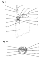
- a clamp fitting 1 arranged in an upper edge region of a pane 2 of an all-glass sliding wing is shown.
- the clamping fitting 1 forms a suspension point of the disc 2, wherein the clamping fitting 1 is attached only by frictional forces on the surfaces of the disc 2.
- the disc 2 is connected in each case by means of the clamping fitting 1 via a retaining screw 16 with a slidably guided in a guide rail trolley.
- the clamping fitting 1 has two clamping plates 3, 8.
- the mutually opposite inner surfaces of the clamping plates 3, 8 are formed parallel to each other and lie respectively with the interposition of a slip-resistant intermediate layer 15 with the set clamping force on the surface of the plane-parallel plate 2.
- Above this clamping region extends from the inside of the clamping plate 8 projecting coupling leg 9 immediately above the upper end of the disc 2. Its width is slightly smaller than or equal to the thickness of the disc 2 with the smallest falling in the adjustment disc thickness.
- the coupling leg 9 is provided on its upper surface with a tooth profile 10, which extends over the entire cross-sectional width of the same.
- the tooth profile 10 comprises in cross-section in this embodiment, a total of five equally sized teeth alternately with five correspondingly large tooth gaps, wherein the teeth are inclined slightly obliquely upward in the direction of the clamping plate 8. These teeth extend over the entire length of the clamping plate. 8
- FIG. 2a engages in this tooth profile 10 a form-fitting a corresponding tooth profile 5, which is formed in the lower surface of a extending in the opposite direction to the coupling leg 9 coupling leg 4.
- This coupling leg 4 with also elongate cross-section extends directly above the coupling leg 9 at right angles to the inside of the other clamping plate.
- This bore web 11 extends in cross section also at right angles from the inside of the clamping plate 8, wherein the planar top of the bore web 11 is at the same height as the upper narrow side of the clamping plate. 3
- the bore web 11 is penetrated in its cross-sectional longitudinal direction of several, in the exemplary embodiment a total of four threaded holes, in each of which a clamping screw 14 can be screwed.
- the ends of the fferenschafte the four arranged in a row clamping screws 14 are axially supported on a flat upper support surface 6 of the clamping plate 3.
- the clamping plates 3, 8 are pressed apart when screwing in the clamping screws 14 in the bore web 11 in the upper region and thereby compressed in the lower, the disc 2 encompassing area.
- the bore web 11 is increased in the central region of the clamping plate 8 to a suspension lug 12, wherein the top of the suspension lug 12 is at the same height as the bore web 11 itself.
- the suspension lug 12 engages in a rectangular recess 7, which from the opposite region of the clamping plate 3 recessed and the upper narrow side of the clamping plate 3 is open.
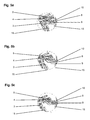
- the adjustment of the clamp fitting 1 for adaptation to three different pane thicknesses is carried out in a simple manner by determining the coverage of the coupling legs 4, 9 by appropriate positioning in a pre-assembly phase, as in the Fig. 4 is shown.
- the coupling leg 4 of the clamping plate 3 is inserted into the cavity between the coupling leg 9 and the bore web 11 and the tooth profiles of the superimposed coupling legs 4, 9 engaged with each other.
- a complete engagement of the tooth profiles 5, 10 can, according to the disc thickness of 8 mm Fig. 5a be provided.
- the coverage must be in accordance with Fig. 5b be reduced by one tooth width.
- a further reduction of the meshing engagement according to a tooth width according to Fig. 5c is required to fit a disc thickness of 12 mm.
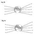
- the retaining screw 16 can be transversely displaced thereto and the screw head 17 thereby insert below the suspension tab 12 through the recess 7 in the clamping fitting 1, wherein the screw shaft in the mounted position penetrates a groove 13 in the suspension lug 12.
- the screw head 17 In the end position of the screw head 17 is partially between the bottom of the bore web 11 and the top coupling leg 4 and is fixed in this position by an unscrewed nut 18 on the suspension lug 12.
- cover 19 which are clipped onto the clamping plates 3, 8, as in the Fig. 3 is shown.
Landscapes
- Engineering & Computer Science (AREA)
- Mechanical Engineering (AREA)
- Securing Of Glass Panes Or The Like (AREA)
- Holding Or Fastening Of Disk On Rotational Shaft (AREA)
Applications Claiming Priority (1)
| Application Number | Priority Date | Filing Date | Title |
|---|---|---|---|
| DE102008004751A DE102008004751B3 (de) | 2008-01-16 | 2008-01-16 | Klemmbeschlag |
Publications (3)
| Publication Number | Publication Date |
|---|---|
| EP2080862A2 true EP2080862A2 (fr) | 2009-07-22 |
| EP2080862A3 EP2080862A3 (fr) | 2013-12-25 |
| EP2080862B1 EP2080862B1 (fr) | 2017-11-15 |
Family
ID=40556129
Family Applications (1)
| Application Number | Title | Priority Date | Filing Date |
|---|---|---|---|
| EP09150597.4A Active EP2080862B1 (fr) | 2008-01-16 | 2009-01-15 | Ferrure de serrage |
Country Status (2)
| Country | Link |
|---|---|
| EP (1) | EP2080862B1 (fr) |
| DE (1) | DE102008004751B3 (fr) |
Cited By (2)
| Publication number | Priority date | Publication date | Assignee | Title |
|---|---|---|---|---|
| DE202010012157U1 (de) | 2010-09-02 | 2010-11-25 | Tittel, Karsten | Türblattbefestigung |
| CN116181172A (zh) * | 2023-03-17 | 2023-05-30 | 朗斯家居股份有限公司 | 一种可拆装上承重锁紧吊夹结构 |
Families Citing this family (3)
| Publication number | Priority date | Publication date | Assignee | Title |
|---|---|---|---|---|
| DE102009027240A1 (de) * | 2009-06-26 | 2010-12-30 | Geze Gmbh | Flügel und Verfahren zur Montage eines Flügels |
| DE102012004941B4 (de) * | 2012-03-12 | 2013-10-10 | Frascio Deutschland Gmbh | Klemmbeschlag |
| DE202019106086U1 (de) | 2019-11-01 | 2021-02-03 | Pauli + Sohn Gmbh Metallwaren | Klemmvorrichtung für einen Türflügel |
Citations (2)
| Publication number | Priority date | Publication date | Assignee | Title |
|---|---|---|---|---|
| DE10064672A1 (de) | 2000-12-23 | 2002-06-27 | Geze Gmbh | Rahmenprofilsystem zur Herstellung eines Profilrahmens eines Flügels einer Tür oder eines Fensters |
| DE69923615T2 (de) | 1998-03-06 | 2006-01-05 | Klein-Iberica S.A. | Montagevorrichtung für Glasschiebetüren |
Family Cites Families (3)
| Publication number | Priority date | Publication date | Assignee | Title |
|---|---|---|---|---|
| EP1052363A1 (fr) * | 1999-05-08 | 2000-11-15 | SKS Stakusit Bautechnik GmbH | Cadre de profilés, notamment de profilés en U pour le maintien d'éléments planes commes des vitres, des panneaux en matière plastique et similaires |
| DE20104198U1 (de) * | 2001-03-12 | 2001-06-07 | Informationstechnik Meng GmbH, 55765 Birkenfeld | Haltevorrichtung |
| DE102008023061B4 (de) * | 2008-05-09 | 2014-08-21 | Geze Gmbh | Klemmbeschlag |
-
2008
- 2008-01-16 DE DE102008004751A patent/DE102008004751B3/de active Active
-
2009
- 2009-01-15 EP EP09150597.4A patent/EP2080862B1/fr active Active
Patent Citations (2)
| Publication number | Priority date | Publication date | Assignee | Title |
|---|---|---|---|---|
| DE69923615T2 (de) | 1998-03-06 | 2006-01-05 | Klein-Iberica S.A. | Montagevorrichtung für Glasschiebetüren |
| DE10064672A1 (de) | 2000-12-23 | 2002-06-27 | Geze Gmbh | Rahmenprofilsystem zur Herstellung eines Profilrahmens eines Flügels einer Tür oder eines Fensters |
Cited By (2)
| Publication number | Priority date | Publication date | Assignee | Title |
|---|---|---|---|---|
| DE202010012157U1 (de) | 2010-09-02 | 2010-11-25 | Tittel, Karsten | Türblattbefestigung |
| CN116181172A (zh) * | 2023-03-17 | 2023-05-30 | 朗斯家居股份有限公司 | 一种可拆装上承重锁紧吊夹结构 |
Also Published As
| Publication number | Publication date |
|---|---|
| EP2080862A3 (fr) | 2013-12-25 |
| DE102008004751B3 (de) | 2009-08-06 |
| EP2080862B1 (fr) | 2017-11-15 |
Similar Documents
| Publication | Publication Date | Title |
|---|---|---|
| EP2815136B2 (fr) | Système de montage | |
| EP2634347B1 (fr) | Support de verre, agencement de profilé et construction de cadre | |
| AT511046B1 (de) | Rahmensystem eines partikelschutzgitters | |
| EP1849952A2 (fr) | Système de montage pour fenêtres et analogues | |
| EP2080862B1 (fr) | Ferrure de serrage | |
| EP2927409B1 (fr) | Joint pour une porte coulissante | |
| DE202012104033U1 (de) | Haltevorrichtung für eine Brüstungs- oder Geländerplatte sowie Geländer oder Brüstung mit Scheibe | |
| EP1500767B1 (fr) | Dispositif de support et de fixation d'encadrements pour portes ou fenêtres à la périphérie d'une ouverture de paroi | |
| EP2050918B1 (fr) | Joint descendant doté d'une ouverture de passage | |
| EP2700778A1 (fr) | Dispositif de soutien déplaçable d'une plaque | |
| DE202004011539U1 (de) | Band für Türen, Fenster u.dgl. | |
| DE102013100922B4 (de) | Laufteil zum Führen eines Möbelteils in einer Führungsrichtung über eine Führungsschiene und Möbelbeschlag | |
| EP1486639B1 (fr) | Joint d'étanchéité descendant pour porte | |
| DE19740603C2 (de) | Stulpschienenbefestigung | |
| DE19808847C2 (de) | Tür- oder Fensterbeschlag | |
| EP1828513B1 (fr) | Bande pour portes, fenêtres et éléments similaires | |
| EP3816383B1 (fr) | Agencement de porte coulissante | |
| DE19712117A1 (de) | Vorrichtung zum Befestigen von Sonnen- oder Blickschutzeinrichtungen | |
| EP2085551A2 (fr) | Dispositif de guidage pour un battant coulissant | |
| EP1659246A1 (fr) | Charnière pour volets | |
| EP1544403B1 (fr) | Vantail, en particulier d'une fenêtre, porte ou paroi | |
| DE102020126347B3 (de) | Abstandhalter, Führungsschiene für einen Raffstore oder eine Jalousie sowie Raffstore und Jalousie und Verfahren hierfür | |
| DE10030337C2 (de) | Gleitschiene mit integrierter Befestigungsvorrichtung | |
| DE202008014536U1 (de) | Schiebetürboxsystem | |
| DE202009014566U1 (de) | Anschlag für eine verschiebbare Tür oder Fenster |
Legal Events
| Date | Code | Title | Description |
|---|---|---|---|
| PUAI | Public reference made under article 153(3) epc to a published international application that has entered the european phase |
Free format text: ORIGINAL CODE: 0009012 |
|
| AK | Designated contracting states |
Kind code of ref document: A2 Designated state(s): AT BE BG CH CY CZ DE DK EE ES FI FR GB GR HR HU IE IS IT LI LT LU LV MC MK MT NL NO PL PT RO SE SI SK TR |
|
| AX | Request for extension of the european patent |
Extension state: AL BA RS |
|
| PUAL | Search report despatched |
Free format text: ORIGINAL CODE: 0009013 |
|
| AK | Designated contracting states |
Kind code of ref document: A3 Designated state(s): AT BE BG CH CY CZ DE DK EE ES FI FR GB GR HR HU IE IS IT LI LT LU LV MC MK MT NL NO PL PT RO SE SI SK TR |
|
| AX | Request for extension of the european patent |
Extension state: AL BA RS |
|
| RIC1 | Information provided on ipc code assigned before grant |
Ipc: E05D 15/06 20060101AFI20131118BHEP |
|
| 17P | Request for examination filed |
Effective date: 20140623 |
|
| RBV | Designated contracting states (corrected) |
Designated state(s): AT BE BG CH CY CZ DE DK EE ES FI FR GB GR HR HU IE IS IT LI LT LU LV MC MK MT NL NO PL PT RO SE SI SK TR |
|
| AKX | Designation fees paid |
Designated state(s): AT BE BG CH CY CZ DE DK EE ES FI FR GB GR HR HU IE IS IT LI LT LU LV MC MK MT NL NO PL PT RO SE SI SK TR |
|
| GRAP | Despatch of communication of intention to grant a patent |
Free format text: ORIGINAL CODE: EPIDOSNIGR1 |
|
| INTG | Intention to grant announced |
Effective date: 20170607 |
|
| GRAS | Grant fee paid |
Free format text: ORIGINAL CODE: EPIDOSNIGR3 |
|
| GRAA | (expected) grant |
Free format text: ORIGINAL CODE: 0009210 |
|
| AK | Designated contracting states |
Kind code of ref document: B1 Designated state(s): AT BE BG CH CY CZ DK EE ES FI FR GB GR HR HU IE IS IT LI LT LU LV MC MK MT NL NO PL PT RO SE SI SK TR |
|
| RBV | Designated contracting states (corrected) |
Designated state(s): AT BE BG CH CY CZ DK EE ES FI FR GB GR HR HU IE IS IT LI LT LU LV MC MK MT NL NO PL PT RO SE SI SK TR |
|
| REG | Reference to a national code |
Ref country code: CH Ref legal event code: EP Ref country code: GB Ref legal event code: FG4D Free format text: NOT ENGLISH Ref country code: DE Ref legal event code: R108 Ref country code: AT Ref legal event code: REF Ref document number: 946454 Country of ref document: AT Kind code of ref document: T Effective date: 20171115 |
|
| REG | Reference to a national code |
Ref country code: IE Ref legal event code: FG4D Free format text: LANGUAGE OF EP DOCUMENT: GERMAN |
|
| REG | Reference to a national code |
Ref country code: NL Ref legal event code: MP Effective date: 20171115 |
|
| REG | Reference to a national code |
Ref country code: LT Ref legal event code: MG4D |
|
| PG25 | Lapsed in a contracting state [announced via postgrant information from national office to epo] |
Ref country code: ES Free format text: LAPSE BECAUSE OF FAILURE TO SUBMIT A TRANSLATION OF THE DESCRIPTION OR TO PAY THE FEE WITHIN THE PRESCRIBED TIME-LIMIT Effective date: 20171115 Ref country code: FI Free format text: LAPSE BECAUSE OF FAILURE TO SUBMIT A TRANSLATION OF THE DESCRIPTION OR TO PAY THE FEE WITHIN THE PRESCRIBED TIME-LIMIT Effective date: 20171115 Ref country code: LT Free format text: LAPSE BECAUSE OF FAILURE TO SUBMIT A TRANSLATION OF THE DESCRIPTION OR TO PAY THE FEE WITHIN THE PRESCRIBED TIME-LIMIT Effective date: 20171115 Ref country code: NL Free format text: LAPSE BECAUSE OF FAILURE TO SUBMIT A TRANSLATION OF THE DESCRIPTION OR TO PAY THE FEE WITHIN THE PRESCRIBED TIME-LIMIT Effective date: 20171115 Ref country code: NO Free format text: LAPSE BECAUSE OF FAILURE TO SUBMIT A TRANSLATION OF THE DESCRIPTION OR TO PAY THE FEE WITHIN THE PRESCRIBED TIME-LIMIT Effective date: 20180215 Ref country code: SE Free format text: LAPSE BECAUSE OF FAILURE TO SUBMIT A TRANSLATION OF THE DESCRIPTION OR TO PAY THE FEE WITHIN THE PRESCRIBED TIME-LIMIT Effective date: 20171115 |
|
| PG25 | Lapsed in a contracting state [announced via postgrant information from national office to epo] |
Ref country code: BG Free format text: LAPSE BECAUSE OF FAILURE TO SUBMIT A TRANSLATION OF THE DESCRIPTION OR TO PAY THE FEE WITHIN THE PRESCRIBED TIME-LIMIT Effective date: 20180215 Ref country code: LV Free format text: LAPSE BECAUSE OF FAILURE TO SUBMIT A TRANSLATION OF THE DESCRIPTION OR TO PAY THE FEE WITHIN THE PRESCRIBED TIME-LIMIT Effective date: 20171115 Ref country code: HR Free format text: LAPSE BECAUSE OF FAILURE TO SUBMIT A TRANSLATION OF THE DESCRIPTION OR TO PAY THE FEE WITHIN THE PRESCRIBED TIME-LIMIT Effective date: 20171115 Ref country code: GR Free format text: LAPSE BECAUSE OF FAILURE TO SUBMIT A TRANSLATION OF THE DESCRIPTION OR TO PAY THE FEE WITHIN THE PRESCRIBED TIME-LIMIT Effective date: 20180216 |
|
| PG25 | Lapsed in a contracting state [announced via postgrant information from national office to epo] |
Ref country code: SK Free format text: LAPSE BECAUSE OF FAILURE TO SUBMIT A TRANSLATION OF THE DESCRIPTION OR TO PAY THE FEE WITHIN THE PRESCRIBED TIME-LIMIT Effective date: 20171115 Ref country code: CZ Free format text: LAPSE BECAUSE OF FAILURE TO SUBMIT A TRANSLATION OF THE DESCRIPTION OR TO PAY THE FEE WITHIN THE PRESCRIBED TIME-LIMIT Effective date: 20171115 Ref country code: DK Free format text: LAPSE BECAUSE OF FAILURE TO SUBMIT A TRANSLATION OF THE DESCRIPTION OR TO PAY THE FEE WITHIN THE PRESCRIBED TIME-LIMIT Effective date: 20171115 Ref country code: CY Free format text: LAPSE BECAUSE OF FAILURE TO SUBMIT A TRANSLATION OF THE DESCRIPTION OR TO PAY THE FEE WITHIN THE PRESCRIBED TIME-LIMIT Effective date: 20171115 Ref country code: EE Free format text: LAPSE BECAUSE OF FAILURE TO SUBMIT A TRANSLATION OF THE DESCRIPTION OR TO PAY THE FEE WITHIN THE PRESCRIBED TIME-LIMIT Effective date: 20171115 |
|
| PG25 | Lapsed in a contracting state [announced via postgrant information from national office to epo] |
Ref country code: PL Free format text: LAPSE BECAUSE OF FAILURE TO SUBMIT A TRANSLATION OF THE DESCRIPTION OR TO PAY THE FEE WITHIN THE PRESCRIBED TIME-LIMIT Effective date: 20171115 Ref country code: RO Free format text: LAPSE BECAUSE OF FAILURE TO SUBMIT A TRANSLATION OF THE DESCRIPTION OR TO PAY THE FEE WITHIN THE PRESCRIBED TIME-LIMIT Effective date: 20171115 |
|
| REG | Reference to a national code |
Ref country code: CH Ref legal event code: PL |
|
| PLBE | No opposition filed within time limit |
Free format text: ORIGINAL CODE: 0009261 |
|
| STAA | Information on the status of an ep patent application or granted ep patent |
Free format text: STATUS: NO OPPOSITION FILED WITHIN TIME LIMIT |
|
| PG25 | Lapsed in a contracting state [announced via postgrant information from national office to epo] |
Ref country code: MT Free format text: LAPSE BECAUSE OF FAILURE TO SUBMIT A TRANSLATION OF THE DESCRIPTION OR TO PAY THE FEE WITHIN THE PRESCRIBED TIME-LIMIT Effective date: 20171115 |
|
| 26N | No opposition filed |
Effective date: 20180817 |
|
| GBPC | Gb: european patent ceased through non-payment of renewal fee |
Effective date: 20180215 |
|
| PG25 | Lapsed in a contracting state [announced via postgrant information from national office to epo] |
Ref country code: LU Free format text: LAPSE BECAUSE OF NON-PAYMENT OF DUE FEES Effective date: 20180115 Ref country code: FR Free format text: LAPSE BECAUSE OF NON-PAYMENT OF DUE FEES Effective date: 20180131 |
|
| REG | Reference to a national code |
Ref country code: IE Ref legal event code: MM4A |
|
| REG | Reference to a national code |
Ref country code: FR Ref legal event code: ST Effective date: 20180928 |
|
| REG | Reference to a national code |
Ref country code: BE Ref legal event code: MM Effective date: 20180131 |
|
| PG25 | Lapsed in a contracting state [announced via postgrant information from national office to epo] |
Ref country code: CH Free format text: LAPSE BECAUSE OF NON-PAYMENT OF DUE FEES Effective date: 20180131 Ref country code: LI Free format text: LAPSE BECAUSE OF NON-PAYMENT OF DUE FEES Effective date: 20180131 Ref country code: SI Free format text: LAPSE BECAUSE OF FAILURE TO SUBMIT A TRANSLATION OF THE DESCRIPTION OR TO PAY THE FEE WITHIN THE PRESCRIBED TIME-LIMIT Effective date: 20171115 Ref country code: BE Free format text: LAPSE BECAUSE OF NON-PAYMENT OF DUE FEES Effective date: 20180131 |
|
| PG25 | Lapsed in a contracting state [announced via postgrant information from national office to epo] |
Ref country code: IE Free format text: LAPSE BECAUSE OF NON-PAYMENT OF DUE FEES Effective date: 20180115 |
|
| PG25 | Lapsed in a contracting state [announced via postgrant information from national office to epo] |
Ref country code: GB Free format text: LAPSE BECAUSE OF NON-PAYMENT OF DUE FEES Effective date: 20180215 |
|
| REG | Reference to a national code |
Ref country code: AT Ref legal event code: MM01 Ref document number: 946454 Country of ref document: AT Kind code of ref document: T Effective date: 20180115 |
|
| PG25 | Lapsed in a contracting state [announced via postgrant information from national office to epo] |
Ref country code: AT Free format text: LAPSE BECAUSE OF NON-PAYMENT OF DUE FEES Effective date: 20180115 |
|
| PG25 | Lapsed in a contracting state [announced via postgrant information from national office to epo] |
Ref country code: MC Free format text: LAPSE BECAUSE OF FAILURE TO SUBMIT A TRANSLATION OF THE DESCRIPTION OR TO PAY THE FEE WITHIN THE PRESCRIBED TIME-LIMIT Effective date: 20171115 |
|
| PG25 | Lapsed in a contracting state [announced via postgrant information from national office to epo] |
Ref country code: TR Free format text: LAPSE BECAUSE OF FAILURE TO SUBMIT A TRANSLATION OF THE DESCRIPTION OR TO PAY THE FEE WITHIN THE PRESCRIBED TIME-LIMIT Effective date: 20171115 |
|
| PG25 | Lapsed in a contracting state [announced via postgrant information from national office to epo] |
Ref country code: PT Free format text: LAPSE BECAUSE OF FAILURE TO SUBMIT A TRANSLATION OF THE DESCRIPTION OR TO PAY THE FEE WITHIN THE PRESCRIBED TIME-LIMIT Effective date: 20171115 Ref country code: HU Free format text: LAPSE BECAUSE OF FAILURE TO SUBMIT A TRANSLATION OF THE DESCRIPTION OR TO PAY THE FEE WITHIN THE PRESCRIBED TIME-LIMIT; INVALID AB INITIO Effective date: 20090115 |
|
| PG25 | Lapsed in a contracting state [announced via postgrant information from national office to epo] |
Ref country code: MK Free format text: LAPSE BECAUSE OF NON-PAYMENT OF DUE FEES Effective date: 20171115 |
|
| PG25 | Lapsed in a contracting state [announced via postgrant information from national office to epo] |
Ref country code: IS Free format text: LAPSE BECAUSE OF FAILURE TO SUBMIT A TRANSLATION OF THE DESCRIPTION OR TO PAY THE FEE WITHIN THE PRESCRIBED TIME-LIMIT Effective date: 20180315 |
|
| P01 | Opt-out of the competence of the unified patent court (upc) registered |
Effective date: 20230510 |
|
| PGFP | Annual fee paid to national office [announced via postgrant information from national office to epo] |
Ref country code: IT Payment date: 20260126 Year of fee payment: 18 |