EP2080907A2 - Lüfteranlage - Google Patents
Lüfteranlage Download PDFInfo
- Publication number
- EP2080907A2 EP2080907A2 EP09150737A EP09150737A EP2080907A2 EP 2080907 A2 EP2080907 A2 EP 2080907A2 EP 09150737 A EP09150737 A EP 09150737A EP 09150737 A EP09150737 A EP 09150737A EP 2080907 A2 EP2080907 A2 EP 2080907A2
- Authority
- EP
- European Patent Office
- Prior art keywords
- hub
- permanent magnet
- fan assembly
- rotation shaft
- fan
- Prior art date
- Legal status (The legal status is an assumption and is not a legal conclusion. Google has not performed a legal analysis and makes no representation as to the accuracy of the status listed.)
- Withdrawn
Links
- 230000000903 blocking effect Effects 0.000 claims abstract description 78
- 239000000463 material Substances 0.000 claims abstract description 51
- 238000000465 moulding Methods 0.000 claims description 52
- 230000008878 coupling Effects 0.000 claims description 13
- 238000010168 coupling process Methods 0.000 claims description 13
- 238000005859 coupling reaction Methods 0.000 claims description 13
- 210000002445 nipple Anatomy 0.000 claims description 6
- 230000006866 deterioration Effects 0.000 description 12
- 238000001816 cooling Methods 0.000 description 7
- 229920005992 thermoplastic resin Polymers 0.000 description 7
- 230000000712 assembly Effects 0.000 description 5
- 238000000429 assembly Methods 0.000 description 5
- 238000007710 freezing Methods 0.000 description 5
- 230000008014 freezing Effects 0.000 description 5
- 238000003780 insertion Methods 0.000 description 4
- 230000037431 insertion Effects 0.000 description 4
- 238000000034 method Methods 0.000 description 4
- 230000008901 benefit Effects 0.000 description 3
- 238000007664 blowing Methods 0.000 description 3
- 239000000428 dust Substances 0.000 description 3
- 238000009413 insulation Methods 0.000 description 3
- 239000012212 insulator Substances 0.000 description 3
- 230000004048 modification Effects 0.000 description 3
- 238000012986 modification Methods 0.000 description 3
- 239000003990 capacitor Substances 0.000 description 2
- 238000000576 coating method Methods 0.000 description 2
- 230000003993 interaction Effects 0.000 description 2
- 238000005057 refrigeration Methods 0.000 description 2
- 238000000926 separation method Methods 0.000 description 2
- 230000006978 adaptation Effects 0.000 description 1
- 230000010062 adhesion mechanism Effects 0.000 description 1
- 239000000853 adhesive Substances 0.000 description 1
- 230000001070 adhesive effect Effects 0.000 description 1
- 230000004888 barrier function Effects 0.000 description 1
- 230000015556 catabolic process Effects 0.000 description 1
- 239000011248 coating agent Substances 0.000 description 1
- 238000010276 construction Methods 0.000 description 1
- 238000006731 degradation reaction Methods 0.000 description 1
- 230000002542 deteriorative effect Effects 0.000 description 1
- 238000010438 heat treatment Methods 0.000 description 1
- 239000000314 lubricant Substances 0.000 description 1
- 230000007257 malfunction Effects 0.000 description 1
- 230000013011 mating Effects 0.000 description 1
- 238000005192 partition Methods 0.000 description 1
- 229920000052 poly(p-xylylene) Polymers 0.000 description 1
- 230000008569 process Effects 0.000 description 1
- 238000004904 shortening Methods 0.000 description 1
- 238000006467 substitution reaction Methods 0.000 description 1
- 238000010257 thawing Methods 0.000 description 1
- XLYOFNOQVPJJNP-UHFFFAOYSA-N water Substances O XLYOFNOQVPJJNP-UHFFFAOYSA-N 0.000 description 1
Images





Classifications
-
- F—MECHANICAL ENGINEERING; LIGHTING; HEATING; WEAPONS; BLASTING
- F25—REFRIGERATION OR COOLING; COMBINED HEATING AND REFRIGERATION SYSTEMS; HEAT PUMP SYSTEMS; MANUFACTURE OR STORAGE OF ICE; LIQUEFACTION SOLIDIFICATION OF GASES
- F25D—REFRIGERATORS; COLD ROOMS; ICE-BOXES; COOLING OR FREEZING APPARATUS NOT OTHERWISE PROVIDED FOR
- F25D17/00—Arrangements for circulating cooling fluids; Arrangements for circulating gas, e.g. air, within refrigerated spaces
- F25D17/04—Arrangements for circulating cooling fluids; Arrangements for circulating gas, e.g. air, within refrigerated spaces for circulating air, e.g. by convection
- F25D17/06—Arrangements for circulating cooling fluids; Arrangements for circulating gas, e.g. air, within refrigerated spaces for circulating air, e.g. by convection by forced circulation
- F25D17/062—Arrangements for circulating cooling fluids; Arrangements for circulating gas, e.g. air, within refrigerated spaces for circulating air, e.g. by convection by forced circulation in household refrigerators
-
- F—MECHANICAL ENGINEERING; LIGHTING; HEATING; WEAPONS; BLASTING
- F04—POSITIVE - DISPLACEMENT MACHINES FOR LIQUIDS; PUMPS FOR LIQUIDS OR ELASTIC FLUIDS
- F04D—NON-POSITIVE-DISPLACEMENT PUMPS
- F04D17/00—Radial-flow pumps, e.g. centrifugal pumps; Helico-centrifugal pumps
- F04D17/08—Centrifugal pumps
- F04D17/16—Centrifugal pumps for displacing without appreciable compression
-
- F—MECHANICAL ENGINEERING; LIGHTING; HEATING; WEAPONS; BLASTING
- F04—POSITIVE - DISPLACEMENT MACHINES FOR LIQUIDS; PUMPS FOR LIQUIDS OR ELASTIC FLUIDS
- F04D—NON-POSITIVE-DISPLACEMENT PUMPS
- F04D25/00—Pumping installations or systems
- F04D25/02—Units comprising pumps and their driving means
- F04D25/06—Units comprising pumps and their driving means the pump being electrically driven
- F04D25/0606—Units comprising pumps and their driving means the pump being electrically driven the electric motor being specially adapted for integration in the pump
- F04D25/0613—Units comprising pumps and their driving means the pump being electrically driven the electric motor being specially adapted for integration in the pump the electric motor being of the inside-out type, i.e. the rotor is arranged radially outside a central stator
-
- F—MECHANICAL ENGINEERING; LIGHTING; HEATING; WEAPONS; BLASTING
- F04—POSITIVE - DISPLACEMENT MACHINES FOR LIQUIDS; PUMPS FOR LIQUIDS OR ELASTIC FLUIDS
- F04D—NON-POSITIVE-DISPLACEMENT PUMPS
- F04D29/00—Details, component parts, or accessories
- F04D29/05—Shafts or bearings, or assemblies thereof, specially adapted for elastic fluid pumps
- F04D29/056—Bearings
- F04D29/057—Bearings hydrostatic; hydrodynamic
-
- F—MECHANICAL ENGINEERING; LIGHTING; HEATING; WEAPONS; BLASTING
- F04—POSITIVE - DISPLACEMENT MACHINES FOR LIQUIDS; PUMPS FOR LIQUIDS OR ELASTIC FLUIDS
- F04D—NON-POSITIVE-DISPLACEMENT PUMPS
- F04D29/00—Details, component parts, or accessories
- F04D29/08—Sealings
- F04D29/083—Sealings especially adapted for elastic fluid pumps
-
- F—MECHANICAL ENGINEERING; LIGHTING; HEATING; WEAPONS; BLASTING
- F25—REFRIGERATION OR COOLING; COMBINED HEATING AND REFRIGERATION SYSTEMS; HEAT PUMP SYSTEMS; MANUFACTURE OR STORAGE OF ICE; LIQUEFACTION SOLIDIFICATION OF GASES
- F25D—REFRIGERATORS; COLD ROOMS; ICE-BOXES; COOLING OR FREEZING APPARATUS NOT OTHERWISE PROVIDED FOR
- F25D17/00—Arrangements for circulating cooling fluids; Arrangements for circulating gas, e.g. air, within refrigerated spaces
- F25D17/04—Arrangements for circulating cooling fluids; Arrangements for circulating gas, e.g. air, within refrigerated spaces for circulating air, e.g. by convection
- F25D17/06—Arrangements for circulating cooling fluids; Arrangements for circulating gas, e.g. air, within refrigerated spaces for circulating air, e.g. by convection by forced circulation
- F25D17/067—Evaporator fan units
-
- F—MECHANICAL ENGINEERING; LIGHTING; HEATING; WEAPONS; BLASTING
- F25—REFRIGERATION OR COOLING; COMBINED HEATING AND REFRIGERATION SYSTEMS; HEAT PUMP SYSTEMS; MANUFACTURE OR STORAGE OF ICE; LIQUEFACTION SOLIDIFICATION OF GASES
- F25D—REFRIGERATORS; COLD ROOMS; ICE-BOXES; COOLING OR FREEZING APPARATUS NOT OTHERWISE PROVIDED FOR
- F25D2317/00—Details or arrangements for circulating cooling fluids; Details or arrangements for circulating gas, e.g. air, within refrigerated spaces, not provided for in other groups of this subclass
- F25D2317/06—Details or arrangements for circulating cooling fluids; Details or arrangements for circulating gas, e.g. air, within refrigerated spaces, not provided for in other groups of this subclass with forced air circulation
- F25D2317/068—Details or arrangements for circulating cooling fluids; Details or arrangements for circulating gas, e.g. air, within refrigerated spaces, not provided for in other groups of this subclass with forced air circulation characterised by the fans
- F25D2317/0681—Details thereof
-
- F—MECHANICAL ENGINEERING; LIGHTING; HEATING; WEAPONS; BLASTING
- F25—REFRIGERATION OR COOLING; COMBINED HEATING AND REFRIGERATION SYSTEMS; HEAT PUMP SYSTEMS; MANUFACTURE OR STORAGE OF ICE; LIQUEFACTION SOLIDIFICATION OF GASES
- F25D—REFRIGERATORS; COLD ROOMS; ICE-BOXES; COOLING OR FREEZING APPARATUS NOT OTHERWISE PROVIDED FOR
- F25D2317/00—Details or arrangements for circulating cooling fluids; Details or arrangements for circulating gas, e.g. air, within refrigerated spaces, not provided for in other groups of this subclass
- F25D2317/06—Details or arrangements for circulating cooling fluids; Details or arrangements for circulating gas, e.g. air, within refrigerated spaces, not provided for in other groups of this subclass with forced air circulation
- F25D2317/068—Details or arrangements for circulating cooling fluids; Details or arrangements for circulating gas, e.g. air, within refrigerated spaces, not provided for in other groups of this subclass with forced air circulation characterised by the fans
- F25D2317/0683—Details or arrangements for circulating cooling fluids; Details or arrangements for circulating gas, e.g. air, within refrigerated spaces, not provided for in other groups of this subclass with forced air circulation characterised by the fans the fans not of the axial type
Definitions
- the present invention relates to a fan assembly, and more particularly, to a fan assembly which prevents an introduction of foreign materials into the fan assembly to avoid a restriction of the movement of rotatable components due to the introduction of the foreign materials, and ultimately the deterioration of such components due to the presence of the foreign materials .
- refrigerators are appliances used to keep items frozen and/or refrigerated therein.
- Related art refrigerators may include a refrigerator main body having a cooling chamber therein and a refrigeration cycle device having a compressor and a condenser, for maintaining a cooled state in the cooling chamber.
- a machine chamber is disposed at a rear region of the refrigerator main body, and the compressor and the condenser are provided in the machine chamber.
- a fan for accelerating air flow is also provided inside the machine chamber so as to facilitate the cooling of the condenser and/or the compressor.
- a cool air channel for allowing the circulation of air in the cooling chamber may be provided at one side of the cooling chamber in the refrigerator main body.
- An evaporator for allowing a heat-exchange of air, and a cool air blower fan for blowing the cool air heat-exchanged through the evaporator into the cooling chamber are provided in the cool air channel.
- the cool air blower fan is disposed at one side of the evaporator, defrosting by the evaporator may occur and unwanted moisture may be generated. In this regard, the moisture may negatively interfere with the operation of the rotatable components and reduces the lifespan of components.
- frost or ice may restrict the movement of the rotatable elements, and thus facilitate a forced deterioration of such components, as well as possible malfunction of the fan's operation.
- the machine chamber may contain a relatively great deal of dust and foreign materials, it may be easy for dust or foreign materials, e.g., bugs, to be introduced between the rotatable elements and the fixed elements of the blowing fan, resulting in further restriction of the movement of the rotatable elements.
- Such foreign materials introduced between the rotatable elements and the fixed elements may also facilitate rapid deterioration of the components, thereby causing malfunctioning and thus further shortening the lifespan of the blowing fan.
- the present invention provides a fan assembly configured to block an introduction of foreign materials.
- a feature of the present invention is to provide a fan assembly capable of preventing foreign materials from entering the fan assembly and deteriorating components therein.
- An additional feature of the present invention is to provide a fan assembly that that is reduced in dimension such that it require less space and may be available for various applications that utilize fan assemblies.
- a non-limiting embodiment provides a fan assembly that may including a rotation shaft, a permanent magnet rotatable around a central axis of the rotation shaft, a fan including a hub having a receiving space therein with one side open and disposed outside the permanent magnet, the fan being rotatable around the central axis of the rotation shaft, a stator disposed inside the permanent magnet, and a blocking portion disposed at the open side of the hub configured to prevent foreign materials from entering an interior of the permanent magnet.
- the fan assembly may include a printed circuit board (PCB) disposed at the open side of the hub, and a molding portion configured to allow the PCB to be integrally connected to an end portion of the stator.
- PCB printed circuit board
- an end portion of the permanent magnet is provided at an interior of the blocking portion such that the blocking portion overlaps the end portion of the permanent magnet in an axial direction.
- the blocking portion may include a rib protruding from the molding portion in an axial direction and extending in a circumferential direction so as to be disposed at one side of at least one of the permanent magnet or the hub.
- the blocking portion may include a first blocking portion provided at the molding portion to overlap one side of an end portion of the permanent magnet in an axial direction, and a second blocking portion provided at the molding portion to overlap one side of an end portion of the hub in the axial direction.
- the hub may be configured to have a cross-section having a diameter gradually increasing toward the open side of the hub.
- the blocking portion may be configured to be disposed at an outer circumferential surface of the hub.
- the blocking portion may protrude from the molding portion, may be disposed outside the hub, and may extend in a circumferential direction.
- a bearing assembly for supporting the rotation shaft may be provided at one side of the molding portion, and the blocking portion may protrude from the bearing assembly and extends around the hub.
- the fan assembly may also include a frame disposed inside the hub, coupled to the rotation shaft, and rotatably supporting the permanent magnet.
- a permanent magnet supporting portion may be configured as a recessed portion of an inner diameter surface of the frame in the radial direction coupling the permanent magnet thereto.
- the hub may further include a nipple protruding from a central area of the hub in an axial direction, and a shaft receiving portion in which an end portion of the rotation shaft is inserted.
- a permanent magnet supporting portion may protrude from an inner surface of the hub in an axial direction and extend in a circumferential direction.
- the present invention is described herein as being used with refrigeration systems, it is not limited to such applications.
- the present invention further contemplates use of the fan assembly in, but not limited to computer systems, HVAC systems, automotive applications, alone, and other known cooling and heating systems.
- a refrigerator may include a refrigerator main body 110 having a freezing chamber 120 and a refrigerating chamber 130 separated by a partition wall 112 therebetween, and a freezing chamber door (not shown) and a refrigerating chamber door (not shown) both coupled to a front surface of the refrigerator main body 110 so as to open/close the interiors of the freezing chamber 120 and the refrigerating chamber 130.
- a cover 121 is disposed at a rear lower region of the freezing chamber 120.
- An evaporator 125 through which air is heat-exchanged to be cooled, is provided at a rear side of the cover 121.
- Inlet holes 122 through which air inside the freezing chamber 120 is introduced, are provided at a lower region of the cover 121.
- a fan assembly 200 in accordance with a non-limiting embodiment of the present invention is disposed above the evaporator 125.
- a cool air duct 127 is disposed at an upper side of the fan assembly 200.
- the cool air duct 127 includes a cool air channel therein such that cool air from the evaporator 125 flows through and is discharged from the cool air channel.
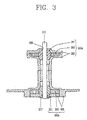
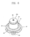
- the fan assembly 200 may include a rotation shaft 211, a permanent magnet 221 having a receiving space therein and rotatable around a central axis of the rotation shaft 211, a fan 230 being rotatable around the central axis of the rotation shaft 211, and including a hub 231 having a receiving space therein with one side open and disposed outside the permanent magnet 221, and a plurality of blades 241 disposed at a circumference of the hub 231, a stator 270 disposed inside the permanent magnet 221, and a blocking portion 290 disposed to overlap at least one of an end portion of the permanent magnet 221 and the open side of the hub 231 by a certain distance in an axial direction.
- the fan assembly 200 may be supported by a mount plate 150.
- the mount plate 150 is provided with a receiving portion 151 in which the fan assembly 200 is partially received.
- the fan 230 may be implemented as a centrifugal fan which includes the hub 231 having one side thereof open and cylindrically formed to have the receiving space therein.
- the present invention contemplates that the hub 231 may be formed in any suitable shape.
- the plurality of blades 241 protrude from the circumference of the hub 231 in the axial direction at spaced intervals and are inclined along the circumferential direction, whereby the fan 230 intakes air in the axial direction and discharges air in a radial direction.
- the rotation shaft 211 is disposed at a central portion of the hub 231.
- a first bearing assembly 260a and a second bearing assembly 260b are coupled to the circumference of the rotation shaft 211 so as to rotatably support the rotation shaft 211.
- the stator 270 is disposed around the first bearing 260a and the second bearing assembly 260b.
- a shaft base 215 is disposed at one end portion of the rotation shaft 211, i.e., a top end portion of the rotation shaft 211 in the drawing.
- the shaft base 215 is integrally rotatably coupled to the central portion of the hub 231 of the fan 230 via a high frequency bonding, although other suitable bonding techniques are contemplated by the present invention.
- a nipple 233 which outwardly protrudes from the central area of the hub 231 in an axial direction includes a shaft receiving portion 235 into which an end portion of the rotation shaft 211 is inserted.
- This construction facilitates a coupling between the rotation shaft 211 and the hub 231 and additionally allows suitable mating between the rotation shaft 211 and the rotational center of the hub 231.
- such components can restrict the rotation shaft 211 and the hub 231 coupled to each other from being moved with respect to a vertical direction.
- a fixing unit e.g., a fixing ring 217, is disposed at the other end of the rotation shaft 211 so as to prevent the separation of the second bearing assembly 260b.
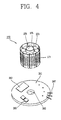
- the stator 270 may include a stator core 271 laminated (or insulated in any suitable manner) in the axial direction, a stator coil 273 wound onto the stator core 271, and an insulator 275 interposed between the stator core 271 and the stator coil 273 for the insulation therebetween.
- a coupling portion 276 coupling the first bearing assembly 260a and the second bearing assembly 260b is provided in a central area of the stator 270.
- the permanent magnet 221 is disposed outside the stator 270 to be spaced apart from the stator 270 with a certain air gap so as to be configured as an outer rotor type motor.
- a molding portion 280 is formed at an end portion of one side of the stator 270, i.e., a bottom end portion of the stator 270 in the drawing.
- a PCB (Printed Circuit Board) 281 is disposed at the bottom side of the stator 270.
- the molding portion 280 may be formed in any suitable shape, such as a disc shape with a certain thickness such that the stator 270 can be integrally connected to the PCB 281.
- the molding portion 280 may be formed of any suitable material, such as thermoplastic resin to cover the bottom end portion of the stator 270 and the PCB 281.
- a permanent magnet supporting portion 237 is provided inside the hub 231 which may be formed in any suitable shape, such as a cylindrical shape, and protrudes parallel with the rotation shaft 211 to extend in the circumferential and axial directions of the hub 231.
- the permanent magnet 221 may be formed in any suitable shape, such as a cylindrical shape, and pole-anisotropically magnetized, whereby the permanent magnet supporting portion 237 does not have to include a back yoke.
- the surface of the permanent magnet 221 is coated with coatings, such as parylene or any suitable coating, so as to prevent a performance degradation due to moisture.
- the permanent magnet 221 is adhered onto an inner diameter surface of the permanent magnet supporting portion 237 with an adhesive, such as Loctite or the like, although other suitable adhesion mechanisms are contemplated by the present invention.
- the blocking portion 290 is provided at the molding portion 280 outside the permanent magnet 221 and the permanent magnet supporting portion 237, such that the blocking portion 290 overlaps a portion of an outer circumferential surface of the permanent magnet 221 and the permanent magnet supporting portion 237 by a certain length in the axial direction. Accordingly, the introduction of external foreign materials inside the permanent magnet supporting portion 237 can be prevented and thus the restriction of the movement of the rotatable elements and the rapid deterioration of the same can also be prevented.
- the first bearing assembly 260a and the second bearing assembly 260b may respectively include a bearing 261 coupled to the circumference of the rotation shaft 211 to rotatably support the rotation shaft 211, a felt 263 containing oil or other suitable lubricants and contacting a circumference of the bearing 261, and housing 265 covering both the bearing 261 and the felt 263.
- the PCB 281 may be formed in any suitable shape, such as a disc, and includes a 3-phase drive integrated circuit (IC) 283, a capacitor 285 and connection terminals 287 to be electrically connected to the exterior.
- IC 3-phase drive integrated circuit
- a through hole 282 in which the second bearing assembly 260b is inserted is provided in the central area of the PCB 281 .
- the molding portion 280 may be formed in any suitable shape, such as a disc shape with a certain thickness by using thermoplastic resin (or any suitable material) such that the stator 270 can be disposed at the upper central area of the PCB 281, and part of the lower end portion of the stator 270 and the PCB 281 can be covered.
- the blocking portion 290 is provided on an upper surface of the molding portion 280, so as to protrude outside the permanent magnet 221 and the permanent magnet supporting portion 237 in the radial direction of the permanent magnet 221, thereby overlapping the permanent magnet 221 and the permanent magnet supporting portion 237 by a certain length in the axial direction.
- the blocking portion 290 is cylindrical in shape (although other suitable shapes are contemplated by the present invention) and extends in a circumferential direction of the permanent magnet 221.
- Cables 284 connected to the PCB 281 are drawn out of one side of the molding portion 280.
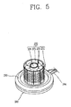
- a mount plate 150 is coupled to a lower side of the molding portion 280. Further, as shown in at least Fig. 5 , the first bearing assembly 260a and the second bearing assembly 260b are coupled to upper and lower sides of the coupling portion 276 of the stator 270, respectively.
- the end portion of the rotation shaft 211 to which the shaft base 215 is coupled is inserted into a shaft opening 266 of the first bearing assembly 260a so as to be protruded to a lower side of the second bearing assembly 260b.
- the fixing ring 217 is coupled to the end portion of the rotation shaft 211 protruding from the outside of the second bearing assembly 260b, thereby preventing the separation of the second bearing assembly 260b, and thus maintaining the first and second bearing assemblies together.
- the permanent magnet 221 and the fan 230 rotate around the central axis of the rotation shaft 211 by the interaction between the stator coil 273 and the permanent magnet 221.
- the first bearing assembly 260a and the second bearing assembly 260b allow smooth rotation of the rotation shaft 211.
- the blocking portion 290 protrudes from the molding portion 280 in the axial direction to overlap the permanent magnet supporting portion 237 by a certain distance, thereby blocking the introduction of external foreign materials inside the permanent magnet supporting portion 237.
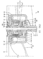
- FIG. 8 A fan assembly in accordance with a second non-limiting embodiment of the present invention will now be described with reference to Fig. 8 .
- the same configurations to the aforementioned and illustrated configurations are given with the same reference numerals for the sake of explanation. Thus, detailed description thereof will not be repeated.
- a fan assembly 300 may include a rotation shaft 211, a permanent magnet 221 having a receiving space therein and rotatable around the central axis of the rotation shaft 211, a fan 230 rotatable around the central axis of the rotation shaft 211, and including a hub 231 having a receiving space therein with one side open and disposed outside the permanent magnet 221, and a plurality of blades 241 disposed at the circumference of the hub 231, a stator 270 provided inside the permanent magnet 221, a first blocking portion 290 disposed to overlap the end portion of the permanent magnet 221 by a certain distance in an axial direction, and a second blocking portion 310 disposed at the open side of the hub 231 to be spaced apart from the first blocking portion 290 in a radial direction.
- the fan 230 may be implemented as a centrifugal fan which includes the hub 231 having one side open and cylindrically formed to have the receiving space therein.
- the present invention also contemplates other suitable shapes for the hub 231.
- the plurality of blades 241 protrude in the axial direction at the circumference of the hub 231 and are inclined along the circumferential direction at spaced intervals, whereby the fan 230 intakes air in the axial direction and discharges air in a radial direction.
- the rotation shaft 211 is disposed at the central portion of the hub 231.
- a first bearing assembly 260a and a second bearing assembly 260b are disposed around the rotation shaft 211 so as to rotatably support the rotation shaft 211.
- the stator 270 is disposed around both the first bearing 260a and the second bearing assembly 260b.
- a shaft base 215 is disposed at one end portion of the rotation shaft 211, so as to be integrally and rotatably coupled to the central portion of the hub 210 of the fan 230 via a high frequency bonding, although other suitable bonding techniques are contemplated by the present invention.
- the stator 270 may include a stator core 271 layered (or insulated in any suitable manner) in the axial direction, a stator coil 273 wound onto the stator core 271, and an insulator 275 interposed between the stator core 271 and the stator coil 273 for the insulation therebetween.
- the permanent magnet 221 is disposed at the outside of the stator 270 with a certain air gap therebetween so as to be integrally rotatable with the hub 231, thereby implementing an outer rotor type motor.
- the permanent magnet supporting portion 237 is provided for supporting the permanent magnet 221.
- the PCB 281 and the molding portion 280 are provided at one side end portion of the stator 270, i.e., at the bottom end portion of the stator 270 in the drawing.
- the molding portion 280 may be formed of any suitable material, such as a thermoplastic resin and in any suitable shape, such as a disc shape with a certain thickness such that the bottom end portion of the stator 270 can be integrally connected to the PCB 281.
- the first blocking portion 290 is provided at an upper surface of the molding portion 280 outside the permanent magnet 221 and the permanent magnet supporting portion 237, so as to overlap the permanent magnet 221 and the permanent magnet supporting portion 237 by a certain length in the axial direction, thereby blocking the introduction of external foreign materials into the receiving space of the permanent magnet 221.
- the second blocking portion 310 is provided inside the hub 231 to protrude along the axial direction of the rotation shaft 211, is spaced apart from the outer diameter surface of the molding portion 280 by a certain distance, and extends along the circumferential direction, thereby being implemented as a shape of a circular rib, although other suitable shapes are contemplated by the present invention. Accordingly, foreign materials outside the hub 231 can be blocked from being introduced inside thereof.
- the permanent magnet 221 and the fan 230 rotate around the central axis of the rotation shaft 211 by the interaction between the stator coil 273 and the permanent magnet 221.
- the second blocking portion 310 blocks foreign materials outside the hub 231 from being introduced inside thereof.
- the first blocking portion 290 can block foreign materials introduced through the second blocking portion 310 from being introduced into the receiving space of the permanent magnet 221.
- a fan assembly 400 may include a rotation shaft 211, a permanent magnet 221 having a receiving space therein and rotating around the central axis of the rotation shaft 211, a fan 430 rotating around the central axis of the rotation shaft 211, and including a hub 431 having a receiving space therein with one side open and disposed outside the permanent magnet 221, and a plurality of blades 441 disposed at a circumference of the hub 431, a stator 270 disposed inside the permanent magnet 221, a PCB 281 disposed at the open side of the hub 431, a molding portion 280 for allowing the PCB 281 to be integrally connected to one end portion of the stator 270, and a blocking portion 410 extending from the end of the hub 431 outside the molding portion 280 in the axial direction to overlap the molding portion 280.
- the fan 430 may be implemented as a propeller type axial flow fan which blows air in an axial direction by including the hub 431 having one side open and may be cylindrically formed (although other suitable shapes are contemplated by the present invention) to have a receiving space therein, and a plurality of blades 441 extending from the circumference of the hub 431 in a radial direction and aligned to be spaced apart from one another in the circumferential direction.
- One side of the fan 430 is supported by a supporting member 160.
- the rotation shaft 211 is disposed at the central portion of the hub 431.
- a first bearing assembly 260a and a second bearing assembly 260b each having a bearing 261, a felt 263 and a housing 265 all for rotatably supporting the rotation shaft 211 are provided at the circumference of the rotation shaft 211.
- the stator 270 is installed around the first and second bearing assemblies 260a and 260b.
- the stator 270 may include a stator core 271 layered in the axial direction, a stator coil 273 wound onto the stator core 271, and an insulator 275 interposed between the stator core 271 and the stator coil 273 for the insulation therebetween.
- a coupling portion 276 for allowing the first bearing assembly 260a and the second bearing assembly 260b to be received for coupling is provided in the central area of the stator 270.
- the permanent magnet 221 is disposed outside the stator 270 with a certain air gap therebetween, thereby configuring an outer rotor type motor.
- One side of the permanent magnet 221 is supported by a frame 225 having one side open in a cylindrical shape, although other suitable shapes are contemplated by the present invention.
- a permanent magnet supporting portion 226 is configured as a recessed portion of an inner diameter surface of the frame 225.
- the frame 225 has an extended inner diameter in the radial direction.
- a stepped portion 228 outwardly protrudes from an end portion of the frame 225.
- a protrusion 227 is disposed at the central area of the stepped portion 228 and is configured to be inserted into the hub 431.
- a shaft coupling portion 433 is provided such that the end portion of the rotation shaft 211 may be inserted therewithin to a certain depth through the central area of the hub 431.
- An insertion bore 435 in which the protrusion 227 is inserted is provided at one side of the shaft coupling portion 433.
- a recess portion 437 is configured to receive the stepped portion 228 therein, and is provided at the circumference of the insertion bore 435.
- the insertion bore 435 may have a length shorter than the length of the protrusion 227, such that the frame 225 may be spaced apart from the inner surface of the hub 431.
- the molding portion 280 having a disc shape is provided at one side end portion of the stator 270, i.e., a bottom end portion of the stator 270.
- the PCB 281 may be formed in any suitable shape, such as a disc shape and has a three-phase drive IC 283 and a capacitor 285 (see Fig. 4 ) aligned at one side of the stator 270.
- the molding portion 280 may be formed of any suitable material, such as a thermoplastic resin to have the disc shape with a certain thickness so as to allow the stator 270 to be integrally connected to the PCB 281.
- the blocking portion 410 is provided at the end of the hub 431 outside the molding portion 280 along the radial direction to be spaced apart from the molding portion 280 by a certain distance, thereby overlapping the molding portion 280 by a certain length in the axial direction. Accordingly, foreign materials outside the hub 431 can be blocked from being introduced into the hub 431 to prevent deterioration of the fan assembly and restriction of the movement of rotatable components due to the presence of foreign materials.
- the blocking portion 410 has the same thickness as that of the hub 431; however, it may be be thicker than the hub 431.
- the blocking portion 410 can block external foreign materials from being introduced into the hub 431, thus preventing the restriction of the movement of the rotatable elements and the deterioration of the fan assembly 400 due to the presence of the foreign materials.
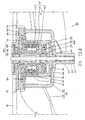
- a fan assembly in accordance with a fourth non-limiting embodiment of the present invention will now be described with reference to Figs. 10 and 11 .
- a fan assembly 450 may include a rotation shaft 211, a permanent magnet 221 having a receiving space therein and rotatable around the central axis of the rotation shaft 211, a fan 430 rotatable around the central axis of the rotation shaft 211, and including a hub 431 having a receiving space therein with one side open and disposed outside the permanent magnet 221, and a plurality of blades 441 disposed at a circumference of the hub 431, a stator 270 disposed inside the permanent magnet 221, a first blocking portion 290 disposed to overlap the end portion of the permanent magnet 221 by a certain distance in an axial direction, and a second blocking portion 410 disposed at the open area of the hub 431 to be spaced apart from the first blocking portion 290 in the radial direction.
- the fan 430 may be implemented as a propeller type axial flow fan which blows air in the axial direction by including the hub 431, and a plurality of blades 441 protruding in the radial direction at the circumference of the hub 431 to be spaced apart from one another in the circumferential direction.
- the rotation shaft 211 is inserted into the central area of the hub 431.
- the first and second bearing assemblies 260a and 260b are disposed at the circumference of the rotation shaft 211 to rotatably support the rotation shaft 211.
- the stator 270 is coupled between the first and second bearing assemblies 260a and 260b.
- the permanent magnet 221 is rotatably coupled to the outside of the stator 270 with a certain air gap therebetween.
- One side of the permanent magnet 221 is supported by the frame 225 integrally coupled both to the rotation shaft 211 and to the hub 431.
- the molding portion 280 having a disc shape (although other suitable shapes are contemplated) is provided at one side of the stator 270 to allow the left end portion of the stator 270 to be integrally connected to the PCB 281.
- the first blocking portion 290 protrudes from one side surface of the molding portion 280 along the radial direction of the permanent magnet 221 outside the permanent magnet supporting portion 226 so as to overlap the permanent magnet supporting portion 226 by a certain length in the axial direction. Accordingly, foreign materials outside the permanent magnet supporting portion 226 can be blocked from being introduced into the receiving space of the permanent magnet 221.
- the second blocking portion 410 extends from the end of the hub 431 in the axial direction outside the molding portion 280, so as to overlap the molding portion 280 by a certain length, whereby foreign materials outside the hub 431 can be blocked from being introduced into the hub 431.
- the second blocking portion 410 has the same thickness as that of the hub 431; however, the second blocking portion 410 may be thicker than the hub 431.
- the second blocking portion 410 blocks foreign materials introduced into the hub 431 from the exterior, and the first blocking portion 290 blocks foreign materials introduced through the second blocking portion 410 from being introduced into the receiving space of the permanent magnet 221, thereby preventing the restriction and forced deterioration of the fan assembly due to the introduction of the foreign materials.
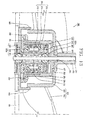
- a fan assembly 500 may include a rotation shaft 211, a permanent magnet 221 having a receiving space therein and rotatable around the central axis of the rotation shaft 211, a fan 430 being rotatable around the central axis of the rotation shaft 211 and including a hub 431 having a receiving space therein with one side open and disposed outside the permanent magnet 221, and a plurality of blades 441 disposed at a circumference of the hub 431, a stator 270 disposed inside the permanent magnet 221, a first blocking portion 290 disposed to overlap the end portion of the permanent magnet 221 by a certain distance in an axial direction, and a second blocking portion 510 disposed at the open area of the hub 431 to be spaced apart from the first blocking portion 290 in the radial direction thereof.
- the fan 430 may be implemented as a propeller type axial flow fan with including the hub 431, and a plurality of blades 441 protruding in the radial direction at the circumference of the hub 431 to be spaced apart from one another in the circumferential direction.
- the stator 270 is disposed inside the hub 431.
- the first bearing assembly 260a and the second bearing assembly 260b are coupled inside the stator 270 so as to support the rotation shaft 211.
- the permanent magnet 221 is disposed outside the stator 270 with a certain air gap therebetween to be rotatably supported by the frame 225.
- a molding portion 280 may be formed of any suitable material, such as a thermoplastic resin in any suitable shape, such as a disc shape, so as to allow the stator 270 to be integrally connected to the PCB 281.
- the first blocking portion 290 protrudes from the upper surface of the molding portion 280 along the radial direction of the permanent magnet 221 outside the permanent magnet supporting portion 226 so as to overlap the permanent magnet supporting portion 226 by a certain length in the axial direction. Accordingly, foreign materials outside the permanent magnet supporting portion 226 can be blocked from being introduced into the receiving space of the permanent magnet 221.
- the second blocking portion 510 protrudes from the molding portion 280 in the radial direction of the molding portion 280 outside the first blocking portion 290 so as to overlap the end portion of the hub 431 by a certain length in the axial direction. Thus, external foreign materials can be blocked from being introduced into the hub 431.
- the second blocking portion 510 blocks external foreign materials from being introduced into the hub 431.
- the first blocking portion 290 blocks foreign materials introduced through the second blocking portion 510 from being introduced into the permanent magnet supporting portion 226, thereby preventing the restriction and forced deterioration of the fan assembly due to the introduction of foreign materials.
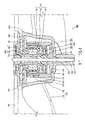
- a fan assembly 550 may include a rotation shaft 211, a permanent magnet 221 having a receiving space therein and rotatable around the central axis of the rotation shaft 211, a fan 430 being rotatable around the central axis of the rotation shaft 211 and including a hub 431 having a receiving space therein with one side open and disposed outside the permanent magnet 221, and a plurality of blades 441 disposed at a circumference of the hub 431, a stator 270 disposed inside the permanent magnet 221, a first blocking portion 290 disposed to overlap the end portion of the permanent magnet 221 in a non-contacted state with each other by a certain distance in an axial direction, and a second blocking portion 560 disposed at the open side of the hub 431 to be spaced apart from the first blocking portion 290 in the radial direction thereof. That is, the second blocking portion 560 is provided at an outer circumferential surface of the hub 431, extends along the outer circumferential surface in a
- the fan 430 may be implemented as a propeller type axial flow fan including the hub 431, and a plurality of blades 441 protruding from the circumference of the hub 431 in the radial direction to be spaced apart from one another in the circumferential direction.
- the stator 270 is disposed inside the hub 431.
- the first bearing assembly 260a and the second bearing assembly 260b are coupled inside the stator 270 so as to support the rotation shaft 211.
- the permanent magnet 221 is disposed outside the stator 270 with a certain air gap therebetween to be rotatably supported by the frame 225.
- the molding portion 280 may be formed of any suitable material, such as a thermoplastic resin in any suitable shape, such as a disc shape, so as to allow the stator 270 to be integrally connected to the PCB 281.
- the first blocking portion 290 protrudes from one side surface of the molding portion 280 along the radial direction of the permanent magnet 221 outside the permanent magnet supporting portion 226 so as to overlap the permanent magnet supporting portion 226 by a certain length in the axial direction. Accordingly, foreign materials outside the permanent magnet supporting portion 226 can be blocked from being introduced into the receiving space of the permanent magnet 221.
- the second bearing assembly 260b is provided at a central portion of an interior space of the second blocking portion 560.
- the second blocking portion 560 may be formed in any suitable shape, such as a cylindrical rib that protrudes from housing 265 outside the hub 431 in the radial direction thereof and spaced apart from the hub 431 by a certain distance, to overlap the hub 431 by a certain length in the axial direction. Accordingly, external foreign materials can be blocked from being introduced into the hub 431.
- the second blocking portion 560 blocks external foreign materials from being introduced into the hub 431.
- the first blocking portion 290 blocks foreign materials introduced through the second blocking portion 560 from being introduced into the permanent magnet supporting portion 226, thereby providing an additional barrier to prevent foreign materials from restricting the movement of rotatable components and the deterioration of the fan assembly.
- a fan assembly 600 may include a rotation shaft 211, a permanent magnet 221 having a receiving space therein and rotatable around the central axis of the rotation shaft 211, a fan 630 being rotatable around the central axis of the rotation shaft 211 and including a hub 631 having a receiving space therein with one side open and disposed outside the permanent magnet 221, and a plurality of blades 441 disposed at a circumference of the hub 631, a stator 270 disposed inside the permanent magnet 221, and a blocking portion 640 disposed at the open area of the hub 631 in an axial direction to block introduction of foreign materials into the receiving space of the permanent magnet 221.
- the fan 630 may be implemented as a propeller type axial flow fan which blows air in the axial direction by including the hub 631, and the plurality of blades 441 protruding in the radial direction at the circumference of the hub 631 to be spaced apart from one another in the circumferential direction.
- the rotation shaft 211 is inserted into the central area of the hub 631 by a certain depth.
- the first bearing assembly 260a and the second bearing assembly 260b are disposed around the rotation shaft 211.
- the stator 270 is coupled between the first bearing assembly 260a and the second bearing assembly 260b.
- the permanent magnet 221 supported by the frame 225 is disposed outside the stator 270 with a certain air gap therebetween.
- a molding portion 280 may be formed of any suitable material, such as a thermoplastic resin in any suitable shape, such as a disc shape with a certain thickness, is provided at one side of the stator 270, i.e., at a bottom end portion of the stator 270, so as to cover both the bottom end portion of the stator 270 and the PCB 281.
- a suitable material such as a thermoplastic resin in any suitable shape, such as a disc shape with a certain thickness
- the hub 631 is configured such that its diameter gradually increases toward its open side, i.e., toward the molding portion 280.
- a shaft coupling portion 633 in which one end portion of the rotation shaft 211 is inserted, outwardly protrudes from an outer surface of the hub 631.
- an insertion bore 635 in which the protrusion 227 of the frame 225 is inserted and a recess portion 637 in which a stepped portion 228 of the frame 225 is received are provided at the hub 631, respectively.
- the blocking portion 640 is configured such that the bottom end portion of the hub 631 is spaced apart from the outer surface portion of the molding portion 280 by a certain distance to overlap each other by a certain length in the axial direction. Accordingly, foreign materials outside the hub 631 can be blocked from being introduced inside through a narrow gap of the overlapped portion of the hub 631.
- the blocking portion 640 has the same thickness as that of the hub 631; however, the blocking portion 640 may be thicker or thinner than the hub 631.
- the blocking portion 640 blocks external foreign materials from being introduced into the hub 631. Accordingly, the restriction and the deterioration of rotatable elements, such as the frame 225, the permanent magnet 221, the rotation shaft 211 and the like, can be prevented.
- foreign materials which may be introduced into a fan through an open side of the fan can be blocked, so as to prevent restriction of the movement of rotatable components, the deterioration of the fan assembly, and a decrease in the operational lifespan of the fan assembly due to the presence of foreign materials.
- a permanent magnet and a stator are disposed inside a hub of the fan and a molding portion and a blocking portion(s) are disposed at an open side of the hub. Accordingly, the length of the fan in an axial direction can be shortened and also the introduction of foreign materials through the open side of the fan can be prevented.
- the molding portion is formed to cover a PCB to protect the PCB from moisture or water.
- the molding portion also allows the integral connection between the stator and the PCB, thus simplifying a fabricating process and reducing a fabricating cost.
- a first blocking portion and a second blocking portion are disposed at the open side of the hub of the fan. Accordingly, foreign materials, e.g., moisture, ice, dust or the like, can more effectively be blocked from being introduced into the fan.
- a permanent magnet rotating outside the stator is disposed inside a centrifugal fan, which allows the fan to decrease in size, both in a radial direction and in an axial direction, resulting in the advantage of minimizing the fan, such that a fan assembly is configured to increase the capacity inside the refrigerator.
- a nipple protruding from the central area of the hub in the axial direction is provided, and a shaft receiving portion in which an end portion of the rotation shaft is inserted is provided in the nipple, so as to facilitate the coupling between the rotation shaft and the hub.
- the nipple is received in the shaft receiving portion, which can facilitate the rotation shaft to match with the central area of the hub and also prevent a relative movement of the rotation shaft and the hub in a vertical direction.
- inventions of the disclosure may be referred to herein, individually and/or collectively, by the term "invention" merely for convenience and without intending to voluntarily limit the scope of this application to any particular invention or inventive concept.
- inventions may be referred to herein, individually and/or collectively, by the term "invention" merely for convenience and without intending to voluntarily limit the scope of this application to any particular invention or inventive concept.
- specific embodiments have been illustrated and described herein, it should be appreciated that any subsequent arrangement designed to achieve the same or similar purpose may be substituted for the specific embodiments shown.
- This disclosure is intended to cover any and all subsequent adaptations or variations of various embodiments. Combinations of the above embodiments, and other embodiments not specifically described herein, will be apparent to those of skill in the art upon reviewing the description.
Landscapes
- Engineering & Computer Science (AREA)
- Mechanical Engineering (AREA)
- General Engineering & Computer Science (AREA)
- Physics & Mathematics (AREA)
- Fluid Mechanics (AREA)
- Chemical & Material Sciences (AREA)
- Combustion & Propulsion (AREA)
- Thermal Sciences (AREA)
- Structures Of Non-Positive Displacement Pumps (AREA)
- Connection Of Motors, Electrical Generators, Mechanical Devices, And The Like (AREA)
- Cold Air Circulating Systems And Constructional Details In Refrigerators (AREA)
Applications Claiming Priority (1)
| Application Number | Priority Date | Filing Date | Title |
|---|---|---|---|
| KR1020080006351A KR101474425B1 (ko) | 2008-01-21 | 2008-01-21 | 냉장고용 팬 조립체 |
Publications (2)
| Publication Number | Publication Date |
|---|---|
| EP2080907A2 true EP2080907A2 (de) | 2009-07-22 |
| EP2080907A3 EP2080907A3 (de) | 2012-06-20 |
Family
ID=40386171
Family Applications (1)
| Application Number | Title | Priority Date | Filing Date |
|---|---|---|---|
| EP09150737A Withdrawn EP2080907A3 (de) | 2008-01-21 | 2009-01-16 | Lüfteranlage |
Country Status (4)
| Country | Link |
|---|---|
| US (1) | US8573954B2 (de) |
| EP (1) | EP2080907A3 (de) |
| KR (1) | KR101474425B1 (de) |
| CN (1) | CN101493098B (de) |
Families Citing this family (20)
| Publication number | Priority date | Publication date | Assignee | Title |
|---|---|---|---|---|
| TWM382382U (en) * | 2009-06-05 | 2010-06-11 | Delta Electronics Inc | An and its stator module and water-repellent structure |
| KR101133365B1 (ko) | 2010-11-18 | 2012-04-06 | 엘지이노텍 주식회사 | 스핀들 모터 |
| US20120126644A1 (en) * | 2010-11-24 | 2012-05-24 | Bill Wu | Waterproof and dustproof motor heat dissipation structure and fan device using the same |
| KR101197950B1 (ko) * | 2011-04-13 | 2012-11-05 | 뉴모텍(주) | 팬 모터 |
| CN107800230A (zh) * | 2011-04-20 | 2018-03-13 | 台达电子工业股份有限公司 | 马达及应用其的风扇 |
| TW201244339A (en) * | 2011-04-20 | 2012-11-01 | Delta Electronics Inc | Motor and fan using the same |
| JP5845862B2 (ja) * | 2011-06-17 | 2016-01-20 | 日本電産株式会社 | モータ |
| US20120112461A1 (en) * | 2011-12-21 | 2012-05-10 | Earth Sure Renewable Energy Corporation | Dual use fan assembly for hvac systems and automotive systems to generate clean alternative elecric energy |
| KR101245456B1 (ko) * | 2012-01-26 | 2013-03-19 | 엘지이노텍 주식회사 | 스핀들 모터 |
| US9057380B2 (en) * | 2012-06-29 | 2015-06-16 | Asia Vital Components Co., Ltd. | Fan having debris entry prevention gap |
| KR20140065026A (ko) | 2012-11-15 | 2014-05-29 | 엘지전자 주식회사 | 슬림형 공기 조화기 |
| EP2936659B1 (de) * | 2012-12-21 | 2020-09-30 | Fisher & Paykel Appliances Limited | Motor |
| KR20160059313A (ko) * | 2014-11-18 | 2016-05-26 | 엘지전자 주식회사 | 팬-모터 조립체 및 이를 구비하는 냉장고 |
| KR101677650B1 (ko) | 2014-12-23 | 2016-11-29 | 엘지전자 주식회사 | 팬-모터 조립체 및 이를 구비한 냉장고 |
| JP6281616B2 (ja) * | 2016-09-16 | 2018-02-21 | 東芝ホームテクノ株式会社 | ファンモータ |
| JP2018178802A (ja) * | 2017-04-07 | 2018-11-15 | 日本電産株式会社 | ファンモータ |
| CN107181334B (zh) * | 2017-05-19 | 2023-07-28 | 嘉善卡固电气设备股份有限公司 | 风机定子及其风机 |
| CN109944819A (zh) * | 2019-04-17 | 2019-06-28 | 深圳市赫瑞科技有限公司 | 一种防腐蚀风扇 |
| CN114600347B (zh) | 2019-11-08 | 2024-08-23 | 松下知识产权经营株式会社 | 风机 |
| CN218542660U (zh) * | 2022-11-15 | 2023-02-28 | 台达电子工业股份有限公司 | 风扇模块 |
Citations (1)
| Publication number | Priority date | Publication date | Assignee | Title |
|---|---|---|---|---|
| US6158985A (en) | 1998-10-07 | 2000-12-12 | Sanyo Denki Co., Ltd. | Air fan including waterproof structure |
Family Cites Families (19)
| Publication number | Priority date | Publication date | Assignee | Title |
|---|---|---|---|---|
| US4934041A (en) * | 1988-07-27 | 1990-06-19 | Nidec Corporation | Method of assembling brushless electric motors |
| US5574321A (en) * | 1994-05-04 | 1996-11-12 | Emerson Electric Co. | Integral refrigerator motor fan blades |
| US5986379A (en) * | 1996-12-05 | 1999-11-16 | General Electric Company | Motor with external rotor |
| US5962938A (en) * | 1997-10-21 | 1999-10-05 | General Electric Company | Motor with external rotor |
| CN2338522Y (zh) * | 1998-05-19 | 1999-09-15 | 曾永昌 | 结构改良的轴流风扇 |
| JP4716065B2 (ja) * | 2000-06-21 | 2011-07-06 | ミネベア株式会社 | 軸流送風機 |
| JP3694224B2 (ja) | 2000-08-22 | 2005-09-14 | 山洋電気株式会社 | 防水構造を備えた遠心ファン |
| US6376946B1 (en) * | 2001-08-23 | 2002-04-23 | Bill Lee | D.C. brushless air fan with an annular oil trough |
| US6572346B2 (en) * | 2001-09-24 | 2003-06-03 | Hsieh Hsin-Mao | Cooling fan |
| US6616422B2 (en) * | 2001-10-09 | 2003-09-09 | Adda Corporation | Cooling fan dust structure for keeping off flying dust from entering into spindle |
| TW595834U (en) * | 2002-05-30 | 2004-06-21 | Hon Hai Prec Ind Co Ltd | A oil-sealed assembly for the motor |
| KR100471444B1 (ko) | 2002-08-14 | 2005-03-08 | 엘지전자 주식회사 | 송풍팬 |
| KR100484828B1 (ko) | 2002-11-27 | 2005-04-22 | 엘지전자 주식회사 | 냉장고의 냉기순환용 축류팬 |
| JP4108488B2 (ja) * | 2003-01-17 | 2008-06-25 | 山洋電気株式会社 | 防水型ブラシレスファンモータ |
| US6940195B2 (en) * | 2003-05-12 | 2005-09-06 | Delta Electronics, Inc. | Fastening structure for securing stator of motor |
| KR100547328B1 (ko) | 2003-09-05 | 2006-01-26 | 엘지전자 주식회사 | 에어컨 실외기의 축류팬 |
| KR100569891B1 (ko) | 2003-12-18 | 2006-04-10 | 엘지전자 주식회사 | 냉장고의 송풍팬 운전 제어방법 |
| JP2005214617A (ja) | 2004-01-28 | 2005-08-11 | Lg Electronics Inc | 横流ファンを有する冷蔵庫 |
| CN100453822C (zh) * | 2006-03-15 | 2009-01-21 | 台达电子工业股份有限公司 | 风扇、马达及其叶轮 |
-
2008
- 2008-01-21 KR KR1020080006351A patent/KR101474425B1/ko active Active
- 2008-12-17 US US12/337,110 patent/US8573954B2/en not_active Expired - Fee Related
-
2009
- 2009-01-16 CN CN2009100025633A patent/CN101493098B/zh active Active
- 2009-01-16 EP EP09150737A patent/EP2080907A3/de not_active Withdrawn
Patent Citations (1)
| Publication number | Priority date | Publication date | Assignee | Title |
|---|---|---|---|---|
| US6158985A (en) | 1998-10-07 | 2000-12-12 | Sanyo Denki Co., Ltd. | Air fan including waterproof structure |
Also Published As
| Publication number | Publication date |
|---|---|
| CN101493098A (zh) | 2009-07-29 |
| US8573954B2 (en) | 2013-11-05 |
| KR101474425B1 (ko) | 2014-12-22 |
| KR20090080425A (ko) | 2009-07-24 |
| US20090185919A1 (en) | 2009-07-23 |
| EP2080907A3 (de) | 2012-06-20 |
| CN101493098B (zh) | 2011-12-21 |
Similar Documents
| Publication | Publication Date | Title |
|---|---|---|
| US8573954B2 (en) | Fan assembly | |
| US10184712B2 (en) | Fan-motor assembly and refrigerator having the same | |
| US8546989B2 (en) | Motor and electrical appliance provided with same | |
| US10054356B2 (en) | Fan-motor assembly including support plate to support fan and motor and refrigerator including the fan-motor assembly | |
| US9745987B2 (en) | Fan | |
| EP2789857B1 (de) | Motorbetriebener Verdichter | |
| US8057195B2 (en) | Outer rotor type fan-motor | |
| EP2080906B1 (de) | Gebläseanordnung | |
| US20180135649A1 (en) | Axial fan and refrigerator | |
| US10767658B2 (en) | Axial fan and refrigerator | |
| JP2009191761A (ja) | 密閉型電動圧縮機 | |
| EP2075473A1 (de) | Ventilatormodul | |
| KR101452763B1 (ko) | 팬-모터 조립체 및 이를 구비한 냉장고 | |
| KR200463568Y1 (ko) | 냉장고 | |
| JP2009138697A (ja) | 車両用コンプレッサ | |
| KR101392926B1 (ko) | 팬-모터 조립체 및 이를 구비한 냉장고 | |
| EP3985837B1 (de) | Ventilatormotor | |
| JP7307591B2 (ja) | 固定子、モータ、圧縮機、及び冷凍装置 | |
| KR20250096476A (ko) | 모터 및 이를 구비하는 공기조화기 | |
| KR20150125358A (ko) | 냉장고용 팬 어셈블리 | |
| KR20150071444A (ko) | 모터 및 이를 포함하는 냉장고 | |
| KR20100029620A (ko) | 팬모터의 팬 |
Legal Events
| Date | Code | Title | Description |
|---|---|---|---|
| PUAI | Public reference made under article 153(3) epc to a published international application that has entered the european phase |
Free format text: ORIGINAL CODE: 0009012 |
|
| AK | Designated contracting states |
Kind code of ref document: A2 Designated state(s): AT BE BG CH CY CZ DE DK EE ES FI FR GB GR HR HU IE IS IT LI LT LU LV MC MK MT NL NO PL PT RO SE SI SK TR |
|
| AX | Request for extension of the european patent |
Extension state: AL BA RS |
|
| PUAL | Search report despatched |
Free format text: ORIGINAL CODE: 0009013 |
|
| AK | Designated contracting states |
Kind code of ref document: A3 Designated state(s): AT BE BG CH CY CZ DE DK EE ES FI FR GB GR HR HU IE IS IT LI LT LU LV MC MK MT NL NO PL PT RO SE SI SK TR |
|
| AX | Request for extension of the european patent |
Extension state: AL BA RS |
|
| RIC1 | Information provided on ipc code assigned before grant |
Ipc: F04D 29/057 20060101ALI20120515BHEP Ipc: F04D 29/08 20060101ALI20120515BHEP Ipc: F04D 25/06 20060101AFI20120515BHEP Ipc: H02K 5/10 20060101ALI20120515BHEP |
|
| 17P | Request for examination filed |
Effective date: 20121220 |
|
| AKX | Designation fees paid |
Designated state(s): AT BE BG CH CY CZ DE DK EE ES FI FR GB GR HR HU IE IS IT LI LT LU LV MC MK MT NL NO PL PT RO SE SI SK TR |
|
| 17Q | First examination report despatched |
Effective date: 20130423 |
|
| STAA | Information on the status of an ep patent application or granted ep patent |
Free format text: STATUS: THE APPLICATION IS DEEMED TO BE WITHDRAWN |
|
| 18D | Application deemed to be withdrawn |
Effective date: 20140916 |