EP2936659B1 - Motor - Google Patents
Motor Download PDFInfo
- Publication number
- EP2936659B1 EP2936659B1 EP13864222.8A EP13864222A EP2936659B1 EP 2936659 B1 EP2936659 B1 EP 2936659B1 EP 13864222 A EP13864222 A EP 13864222A EP 2936659 B1 EP2936659 B1 EP 2936659B1
- Authority
- EP
- European Patent Office
- Prior art keywords
- rotor
- motor
- stator
- configurations
- poles
- Prior art date
- Legal status (The legal status is an assumption and is not a legal conclusion. Google has not performed a legal analysis and makes no representation as to the accuracy of the status listed.)
- Active
Links
- 239000012212 insulator Substances 0.000 claims description 23
- 229920001971 elastomer Polymers 0.000 claims description 17
- 239000005060 rubber Substances 0.000 claims description 17
- 238000004804 winding Methods 0.000 claims description 15
- 230000004323 axial length Effects 0.000 claims description 12
- 239000008393 encapsulating agent Substances 0.000 claims description 9
- 230000008878 coupling Effects 0.000 claims description 4
- 238000010168 coupling process Methods 0.000 claims description 4
- 238000005859 coupling reaction Methods 0.000 claims description 4
- 239000000463 material Substances 0.000 description 36
- 238000004378 air conditioning Methods 0.000 description 20
- XBBZAULFUPBZSP-UHFFFAOYSA-N 2,4-dichloro-1-(3-chlorophenyl)benzene Chemical compound ClC1=CC(Cl)=CC=C1C1=CC=CC(Cl)=C1 XBBZAULFUPBZSP-UHFFFAOYSA-N 0.000 description 11
- 239000004033 plastic Substances 0.000 description 11
- 229920003023 plastic Polymers 0.000 description 11
- 230000000295 complement effect Effects 0.000 description 9
- 239000002245 particle Substances 0.000 description 6
- 238000010276 construction Methods 0.000 description 5
- 230000004907 flux Effects 0.000 description 5
- 239000004412 Bulk moulding compound Substances 0.000 description 4
- XRWSZZJLZRKHHD-WVWIJVSJSA-N asunaprevir Chemical compound O=C([C@@H]1C[C@H](CN1C(=O)[C@@H](NC(=O)OC(C)(C)C)C(C)(C)C)OC1=NC=C(C2=CC=C(Cl)C=C21)OC)N[C@]1(C(=O)NS(=O)(=O)C2CC2)C[C@H]1C=C XRWSZZJLZRKHHD-WVWIJVSJSA-N 0.000 description 4
- 238000005452 bending Methods 0.000 description 4
- 229940125961 compound 24 Drugs 0.000 description 4
- -1 Polybutylene Polymers 0.000 description 3
- 229910000831 Steel Inorganic materials 0.000 description 3
- 238000000465 moulding Methods 0.000 description 3
- 239000010959 steel Substances 0.000 description 3
- 244000043261 Hevea brasiliensis Species 0.000 description 2
- 230000005540 biological transmission Effects 0.000 description 2
- 239000002131 composite material Substances 0.000 description 2
- 230000001143 conditioned effect Effects 0.000 description 2
- 238000001816 cooling Methods 0.000 description 2
- 230000007423 decrease Effects 0.000 description 2
- 230000000694 effects Effects 0.000 description 2
- 238000005538 encapsulation Methods 0.000 description 2
- 229920006351 engineering plastic Polymers 0.000 description 2
- 229920003052 natural elastomer Polymers 0.000 description 2
- 229920001194 natural rubber Polymers 0.000 description 2
- 229920001748 polybutylene Polymers 0.000 description 2
- 229920003051 synthetic elastomer Polymers 0.000 description 2
- 239000005061 synthetic rubber Substances 0.000 description 2
- 229910000859 α-Fe Inorganic materials 0.000 description 2
- 241001247986 Calotropis procera Species 0.000 description 1
- 230000005355 Hall effect Effects 0.000 description 1
- XEEYBQQBJWHFJM-UHFFFAOYSA-N Iron Chemical compound [Fe] XEEYBQQBJWHFJM-UHFFFAOYSA-N 0.000 description 1
- 239000004677 Nylon Substances 0.000 description 1
- 239000004743 Polypropylene Substances 0.000 description 1
- 230000002238 attenuated effect Effects 0.000 description 1
- 239000011230 binding agent Substances 0.000 description 1
- 239000000919 ceramic Substances 0.000 description 1
- 210000000078 claw Anatomy 0.000 description 1
- 230000001419 dependent effect Effects 0.000 description 1
- 238000006073 displacement reaction Methods 0.000 description 1
- 230000005489 elastic deformation Effects 0.000 description 1
- 229920006334 epoxy coating Polymers 0.000 description 1
- 239000011521 glass Substances 0.000 description 1
- 238000004519 manufacturing process Methods 0.000 description 1
- 229910052751 metal Inorganic materials 0.000 description 1
- 239000002184 metal Substances 0.000 description 1
- 238000000034 method Methods 0.000 description 1
- 238000012986 modification Methods 0.000 description 1
- 230000004048 modification Effects 0.000 description 1
- 229920001778 nylon Polymers 0.000 description 1
- 239000002861 polymer material Substances 0.000 description 1
- 229920001155 polypropylene Polymers 0.000 description 1
- 229920001296 polysiloxane Polymers 0.000 description 1
- 230000008569 process Effects 0.000 description 1
- 230000010349 pulsation Effects 0.000 description 1
- 229910052761 rare earth metal Inorganic materials 0.000 description 1
- 150000002910 rare earth metals Chemical class 0.000 description 1
- 239000012858 resilient material Substances 0.000 description 1
- 230000004044 response Effects 0.000 description 1
- 230000000717 retained effect Effects 0.000 description 1
- 238000005096 rolling process Methods 0.000 description 1
- 230000007480 spreading Effects 0.000 description 1
- 238000003892 spreading Methods 0.000 description 1
- 238000005728 strengthening Methods 0.000 description 1
- 229920001059 synthetic polymer Polymers 0.000 description 1
- 239000004634 thermosetting polymer Substances 0.000 description 1
Images





Classifications
-
- H—ELECTRICITY
- H02—GENERATION; CONVERSION OR DISTRIBUTION OF ELECTRIC POWER
- H02K—DYNAMO-ELECTRIC MACHINES
- H02K7/00—Arrangements for handling mechanical energy structurally associated with dynamo-electric machines, e.g. structural association with mechanical driving motors or auxiliary dynamo-electric machines
- H02K7/08—Structural association with bearings
- H02K7/085—Structural association with bearings radially supporting the rotary shaft at only one end of the rotor
-
- F—MECHANICAL ENGINEERING; LIGHTING; HEATING; WEAPONS; BLASTING
- F04—POSITIVE - DISPLACEMENT MACHINES FOR LIQUIDS; PUMPS FOR LIQUIDS OR ELASTIC FLUIDS
- F04D—NON-POSITIVE-DISPLACEMENT PUMPS
- F04D17/00—Radial-flow pumps, e.g. centrifugal pumps; Helico-centrifugal pumps
- F04D17/02—Radial-flow pumps, e.g. centrifugal pumps; Helico-centrifugal pumps having non-centrifugal stages, e.g. centripetal
- F04D17/04—Radial-flow pumps, e.g. centrifugal pumps; Helico-centrifugal pumps having non-centrifugal stages, e.g. centripetal of transverse-flow type
-
- F—MECHANICAL ENGINEERING; LIGHTING; HEATING; WEAPONS; BLASTING
- F04—POSITIVE - DISPLACEMENT MACHINES FOR LIQUIDS; PUMPS FOR LIQUIDS OR ELASTIC FLUIDS
- F04D—NON-POSITIVE-DISPLACEMENT PUMPS
- F04D25/00—Pumping installations or systems
- F04D25/02—Units comprising pumps and their driving means
- F04D25/06—Units comprising pumps and their driving means the pump being electrically driven
- F04D25/0606—Units comprising pumps and their driving means the pump being electrically driven the electric motor being specially adapted for integration in the pump
- F04D25/0613—Units comprising pumps and their driving means the pump being electrically driven the electric motor being specially adapted for integration in the pump the electric motor being of the inside-out type, i.e. the rotor is arranged radially outside a central stator
- F04D25/062—Details of the bearings
-
- F—MECHANICAL ENGINEERING; LIGHTING; HEATING; WEAPONS; BLASTING
- F04—POSITIVE - DISPLACEMENT MACHINES FOR LIQUIDS; PUMPS FOR LIQUIDS OR ELASTIC FLUIDS
- F04D—NON-POSITIVE-DISPLACEMENT PUMPS
- F04D25/00—Pumping installations or systems
- F04D25/02—Units comprising pumps and their driving means
- F04D25/06—Units comprising pumps and their driving means the pump being electrically driven
- F04D25/0606—Units comprising pumps and their driving means the pump being electrically driven the electric motor being specially adapted for integration in the pump
- F04D25/0613—Units comprising pumps and their driving means the pump being electrically driven the electric motor being specially adapted for integration in the pump the electric motor being of the inside-out type, i.e. the rotor is arranged radially outside a central stator
- F04D25/064—Details of the rotor
-
- F—MECHANICAL ENGINEERING; LIGHTING; HEATING; WEAPONS; BLASTING
- F04—POSITIVE - DISPLACEMENT MACHINES FOR LIQUIDS; PUMPS FOR LIQUIDS OR ELASTIC FLUIDS
- F04D—NON-POSITIVE-DISPLACEMENT PUMPS
- F04D25/00—Pumping installations or systems
- F04D25/02—Units comprising pumps and their driving means
- F04D25/06—Units comprising pumps and their driving means the pump being electrically driven
- F04D25/0606—Units comprising pumps and their driving means the pump being electrically driven the electric motor being specially adapted for integration in the pump
- F04D25/0613—Units comprising pumps and their driving means the pump being electrically driven the electric motor being specially adapted for integration in the pump the electric motor being of the inside-out type, i.e. the rotor is arranged radially outside a central stator
- F04D25/0646—Details of the stator
-
- H—ELECTRICITY
- H02—GENERATION; CONVERSION OR DISTRIBUTION OF ELECTRIC POWER
- H02K—DYNAMO-ELECTRIC MACHINES
- H02K1/00—Details of the magnetic circuit
- H02K1/06—Details of the magnetic circuit characterised by the shape, form or construction
- H02K1/12—Stationary parts of the magnetic circuit
- H02K1/18—Means for mounting or fastening magnetic stationary parts on to, or to, the stator structures
- H02K1/187—Means for mounting or fastening magnetic stationary parts on to, or to, the stator structures to inner stators
-
- H—ELECTRICITY
- H02—GENERATION; CONVERSION OR DISTRIBUTION OF ELECTRIC POWER
- H02K—DYNAMO-ELECTRIC MACHINES
- H02K1/00—Details of the magnetic circuit
- H02K1/06—Details of the magnetic circuit characterised by the shape, form or construction
- H02K1/22—Rotating parts of the magnetic circuit
- H02K1/27—Rotor cores with permanent magnets
- H02K1/2786—Outer rotors
- H02K1/2787—Outer rotors the magnetisation axis of the magnets being perpendicular to the rotor axis
- H02K1/2789—Outer rotors the magnetisation axis of the magnets being perpendicular to the rotor axis the rotor consisting of two or more circumferentially positioned magnets
- H02K1/2791—Surface mounted magnets; Inset magnets
-
- H—ELECTRICITY
- H02—GENERATION; CONVERSION OR DISTRIBUTION OF ELECTRIC POWER
- H02K—DYNAMO-ELECTRIC MACHINES
- H02K1/00—Details of the magnetic circuit
- H02K1/06—Details of the magnetic circuit characterised by the shape, form or construction
- H02K1/22—Rotating parts of the magnetic circuit
- H02K1/28—Means for mounting or fastening rotating magnetic parts on to, or to, the rotor structures
- H02K1/30—Means for mounting or fastening rotating magnetic parts on to, or to, the rotor structures using intermediate parts, e.g. spiders
-
- H—ELECTRICITY
- H02—GENERATION; CONVERSION OR DISTRIBUTION OF ELECTRIC POWER
- H02K—DYNAMO-ELECTRIC MACHINES
- H02K3/00—Details of windings
- H02K3/46—Fastening of windings on the stator or rotor structure
- H02K3/52—Fastening salient pole windings or connections thereto
- H02K3/521—Fastening salient pole windings or connections thereto applicable to stators only
- H02K3/522—Fastening salient pole windings or connections thereto applicable to stators only for generally annular cores with salient poles
-
- H—ELECTRICITY
- H02—GENERATION; CONVERSION OR DISTRIBUTION OF ELECTRIC POWER
- H02K—DYNAMO-ELECTRIC MACHINES
- H02K5/00—Casings; Enclosures; Supports
- H02K5/04—Casings or enclosures characterised by the shape, form or construction thereof
- H02K5/16—Means for supporting bearings, e.g. insulating supports or means for fitting bearings in the bearing-shields
- H02K5/167—Means for supporting bearings, e.g. insulating supports or means for fitting bearings in the bearing-shields using sliding-contact or spherical cap bearings
- H02K5/1675—Means for supporting bearings, e.g. insulating supports or means for fitting bearings in the bearing-shields using sliding-contact or spherical cap bearings radially supporting the rotary shaft at only one end of the rotor
-
- H—ELECTRICITY
- H02—GENERATION; CONVERSION OR DISTRIBUTION OF ELECTRIC POWER
- H02K—DYNAMO-ELECTRIC MACHINES
- H02K5/00—Casings; Enclosures; Supports
- H02K5/04—Casings or enclosures characterised by the shape, form or construction thereof
- H02K5/16—Means for supporting bearings, e.g. insulating supports or means for fitting bearings in the bearing-shields
- H02K5/173—Means for supporting bearings, e.g. insulating supports or means for fitting bearings in the bearing-shields using bearings with rolling contact, e.g. ball bearings
- H02K5/1735—Means for supporting bearings, e.g. insulating supports or means for fitting bearings in the bearing-shields using bearings with rolling contact, e.g. ball bearings radially supporting the rotary shaft at only one end of the rotor
-
- H—ELECTRICITY
- H02—GENERATION; CONVERSION OR DISTRIBUTION OF ELECTRIC POWER
- H02K—DYNAMO-ELECTRIC MACHINES
- H02K21/00—Synchronous motors having permanent magnets; Synchronous generators having permanent magnets
- H02K21/12—Synchronous motors having permanent magnets; Synchronous generators having permanent magnets with stationary armatures and rotating magnets
- H02K21/22—Synchronous motors having permanent magnets; Synchronous generators having permanent magnets with stationary armatures and rotating magnets with magnets rotating around the armatures, e.g. flywheel magnetos
-
- H—ELECTRICITY
- H02—GENERATION; CONVERSION OR DISTRIBUTION OF ELECTRIC POWER
- H02K—DYNAMO-ELECTRIC MACHINES
- H02K2203/00—Specific aspects not provided for in the other groups of this subclass relating to the windings
- H02K2203/12—Machines characterised by the bobbins for supporting the windings
-
- H—ELECTRICITY
- H02—GENERATION; CONVERSION OR DISTRIBUTION OF ELECTRIC POWER
- H02K—DYNAMO-ELECTRIC MACHINES
- H02K7/00—Arrangements for handling mechanical energy structurally associated with dynamo-electric machines, e.g. structural association with mechanical driving motors or auxiliary dynamo-electric machines
- H02K7/14—Structural association with mechanical loads, e.g. with hand-held machine tools or fans
Definitions
- the present invention generally relates to a motor, and more specifically relates to a motor for an air-conditioning unit and an air-conditioning unit comprising a motor.
- BLDC brushless direct current
- a known motor construction is an internal stator with radially outwardly extending electrically commutated poles, and an external rotor with permanent magnet poles arranged circumferentially and facing outer ends of the stator poles.
- Such a motor configuration may be described as an inside-out BLDC motor.
- Inside-out BLDC motors have been used in air-conditioning units.
- the motor is used to drive a fan or blower of the air-conditioning unit.
- the fan or blower typically has an axial length that is many times the axial length of the motor.
- One end of the fan is coupled to the motor and an opposite end is supported by a bearing arrangement.
- Vibration generated in the motor preferably is substantially isolated from the fan and motor mounting supports for quiet operation of the fan and the related air-conditioning unit.
- the fan or blower of a modern air-conditioning unit typically has a diameter of about 100mm.
- the motor preferably is of a compact size commensurate with the diameter of the fan and the motor preferably has a compact axial length.
- the motor and the connection of the motor to the fan assembly preferably comprises few components.
- US6362554B discloses a high speed spindle motor.
- US6333576B discloses a brushless air-conditioner motor.
- US3474272A discloses a wobbling rotor step motor with a ball joint between its rotor and rotor shaft.
- JP 2008 088831 A discloses an electrical motor for an air-conditioning indoor-unit.
- the present invention consists in a motor comprising:
- the present invention consists in a motor comprising:
- the motor comprises the compliant mount and the compliant mount is an elastomeric sleeve or rubber sleeve providing a resilient mount for the bearing element.
- the bearing element is axially located at or near to a magnetic centre plane of the motor.
- the distance between an axial centre of the bearing element and the magnetic centre plane of the motor is less than about 20% of the axial length of the annular core.
- the compliant mount is a ball joint comprising a ball component received in a socket.
- the bearing locating member comprises a radially inward facing surface or surfaces and an axial facing surface for mounting the bearing element radially and axially.
- the motor comprises an encapsulant encapsulating the annular core, the phase windings, and the bearing locating member, the encapsulant rigidly supporting the bearing locating member.
- the term 'radial' or the phrase 'radial length' or 'radial depth' as used in this specification and claims is not intended to be limited to mean a length or depth dimension of an element or part or an element or part that is oriented purely radially with respect to a centre.
- the term 'radial' or the phrase 'radial length' or 'radial depth' is also intended to describe a dimension of an element or part or an element or part that is oriented in a direction between a radial direction and a tangential direction with respect to a centre. For example, a component that extends outwardly relative to a centre at an angle to a radial line extending from the centre or is curved relative to a radial line extending from the centre is also to be interpreted as extending radially.
- air-conditioning unit may refer to any equipment that forms part of an air-conditioning system, for example a blower unit to be used to blow conditioned air into a room or space being conditioned.
- a motor that is arranged and configured in accordance with certain features, aspects and advantages of an embodiment of the present invention is described with reference to Figures 1 to 3 .
- a preferred use for the illustrated motor is for driving a fan in an air-conditioning unit. Accordingly, certain features, aspects and advantages of the present invention relate to configuring the motor for such a preferred use.
- the illustrated motor 10 comprises an internal stator 20 and an external rotor 50.
- the stator 20 is shown in an exploded view in Figure 3 and comprises a magnetically permeable core 21 comprising an annular ring portion and a plurality of poles extending radially outward from the outside of the annular ring portion.
- the core 21 may be helically wound from a strip element comprising a longitudinal base with teeth extending generally perpendicular to the longitudinal base.
- the strip can be wound in a coil to form a multi-layered core.
- the core 21 may be assembled by stacking separate layers, each layer formed as a single part or comprising multiple segments. Each layer or layer segment may be stamped from a parent sheet material or wound from a strip element.
- the core 21 may be sintered or formed from a mouldable soft magnetic composite.
- the core 21 may for formed from, for example, a soft magnetic composite comprising iron powder particles separated with an electrically insulating layer.
- An insulator structure 22 can surround at least a portion of the core 21 or, in some configurations, most of the core 21.
- Conductive windings 23 can be arranged on the poles.
- the insulator structure 22 is over-moulded to the core 21.
- the insulator structure 22 is separately moulded and subsequently assembled to the core 21.
- the insulator structure 22 may be formed as a separately moulded part, or may be separately moulded in two or more parts that are each assembled to the core to form the insulator.
- One suitable plastic material for moulding or over-moluding the insulator structure 22 is PBT (Polybutylene Teraphthalate).
- the stator core 21 may be insulated by an epoxy coating, for example but without limitation.
- the stator components e.g., the core 21, the insulator structure 22 and the windings 23
- the compound 24 can comprise, for example but without limitation, a thermoset resin.
- the PCB 25 may also comprise sensors that can be used for motor control.
- the sensors can include hall-effect sensors 26 that are used to sense rotor position, for example but without limitation.
- Figure 3 illustrates the PCB 25 without electronic components and electric connections to the stator pole windings 23.
- the bulk moulding compound 24 (hereinafter also referred to as “encapsulant” or “encapsulating material”) provides a mounting portion for mounting the stator 20 to a support structure.
- the mounting portion may be an annular rim 37 extending around a circumference of the stator as shown in Figures 1 and 3 .
- the support structure can comprise, for example but without limitation, a chassis of an air-conditioning unit.
- a rubber isolator or boot 27 can be provided over the mounting portion of the encapsulating material 24.
- the rubber boot or rubber isolator 27 surrounds the perimeter of the PCB 25, and the PCB 25, including components mounted on the PCB 25, the stator core 21, the core insulator structure 22 and the windings 23 are encapsulated by the bulk moulding compound to also encapsulate the PCB 25 and the components mounted to the PCB 25 within the stator assembly 20.
- the PCB 25 can be encapsulated at the axial location of the mounting portion of the encapsulating material 24. In some configurations, the PCB 25 and the PCB-mounted components are completely encased by the encapsulant 24.
- the motor 10 can be clamped about the outside of the rubber boot or isolator 27 into a device assembly, such as the air-conditioning unit, to securely mount the motor 10 to a chassis 90 or other portion of the air-conditioning unit.
- the rubber boot or isolator 27 provides a resilient mount for the motor 10 because the rubber boot or isolator 27 is held between a clamp 91 of the chassis of the unit and the rigid encapsulant 24.
- the rubber boot or isolator 27 is retained in a clamp that is fixed to the chassis.
- the resilient boot 27 is resilient enough to dampen vibrations.
- the rubber boot or isolator 27 provides sufficient stiffness to provide secure mounting of the stator 20.
- the rubber material of the boot 27 has a Shore A hardness of between about 40 and about 80 with a thickness of between about 1mm and about 5mm.
- the illustrated rubber boot 27 is annular with generally U-shaped or C-shaped cross-section that defines a radially inwardly opening (or facing) recess.
- the resilient boot 27 can be received within a groove in the clamp that is used to radially and axially secure the stator.
- a perimeter of the PCB 25 may be located within the recess defined by the U-shaped or C-shaped cross-section of the boot 27.
- the boot 27 may comprise a radially outwardly opening (or facing) recess defined by the U-shaped or C-shaped cross-section.
- a corresponding rim or protrusions in the chassis 90 and/or the clamp 91 can be provided to interface with the outwardly opening (or facing) recess of the U-shaped cross-section.
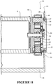
- the stator 20 of Figure 11 comprises an annular groove 28 around a circumference of the stator for receiving the annular resilient member 27.
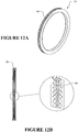
- the resilient member 27 provides an outwardly facing annular channel 29 ( Figure 12B ), having a substantially U- or V-shaped cross-section, for receiving a clamp or holding feature of the air-conditioning unit support structure or chassis for example.
- a fan for example fan 5 in Figures 1 and 2 , creates a higher air pressure on the fan side of the stator. This higher air pressure could result in air transfer past the motor.
- the member 27 also provides an air seal to prevent air passing from the fan side of the stator past the stator.
- the annular resilient member or isolating member 27 has a plurality of projections spaced apart circumferentially around an axial facing surface.
- the projections may assist in dampening vibrations by providing more resiliency to the isolating member.
- the isolating member 27 comprises projections 44 formed on the inside surface of the radially outwardly facing annular channel 29 provided in the member 27.
- the projections 44 may be provided on an outwardly facing surface or surfaces of the annular resilient member 27 for contacting the inner surface of a radially inwardly facing opening or recess provided, for example, in clamp 91 (see Figure 1 ).
- the projections may be provided on first 45 and a second 46 axially separated, generally oppositely facing, annular surfaces of the annular resilient member 27 (see Figure 11 , for example).
- the projections are formed as radial ribs spaced apart circumferentially around the annular resilient member 27.
- the radial ribs may be arranged to form a saw-tooth pattern extending circumferentially around the resilient member 27.
- the projections may be formed as domes spaced apart circumferentially around the resilient member.
- the projections may have an angular circumferential spacing of between about 2 and 3 degrees.
- the projections may have an axial height above the nominal surface of the resilient member of about 0.5mm to about 1.5mm, or more preferably about 0.5mm to about 1.0mm, or even more preferably about 0.6mm to about 1.0mm, or still more preferably about 0.7mm to about 0.9mm.
- first 45 and second 46 axially separated facing annular surfaces are arranged at an angle to a transverse (or radial) plane of the stator so that when clamped by the support structure the axially separated facing surfaces position the stator both axially and radially.
- the axially separated facing surfaces are angled, from a plane perpendicular to the motor axis 6, at about 5 to about 10 degrees, or more preferably at about 6 to about 10 degrees, or even more preferably at about 7 to about 9 degrees.
- the rotor 50 can comprise a rotor frame 51 with permanent magnet poles 52 that are formed in a ring.
- the poles 52 on the rotor frame 51 can circumscribe the outside of the stator and can face the ends of the stator poles.
- the permanent magnet poles 52 comprise a single ring of magnet material.
- the permanent magnet poles 52 comprise a single ring of magnet material that is fabricated from a mouldable plastic-ferrite.
- individual magnets are arranged in a ring.
- the phrase "a ring of magnet material" should be interpreted to mean both a continuous ring of magnet material and separate magnet elements arranged to form a substantially circumferential ring with or without a circumferential space or gap between each magnet element.
- the illustrated rotor frame 51 comprises a hub 53 at a rotational axis 6 of the motor 10.
- the hub 53 supports the rotor poles 52 for rotation about the axis.
- the rotor frame 51 also comprises a circumferential side wall 54 for positioning the magnet poles 52 outside the stator 20, and at least one member 55 (for example, a disc or end wall) extending between the hub 53 and the circumferential side wall 54.
- the circumferential wall 54 is generally cylindrical.
- the rotor 50 comprises a rotor axle 56.
- the rotor axle extends or projects axially from the rotor hub 53 to the inside of the annular core 21 of the stator 20.
- a bearing element 57 for example a rolling bearing with balls, needles, rollers or the like positioned between an inner race and an outer race, is located within the stator 20. In some configurations, the bearing element 57 can omit one or more of the inner race and the outer race.
- the bearing element 57 rotationally couples the rotor 50 to the stator 20 via the rotor axle 56 about the rotational axis 6 ( Figure 1 ).
- the bearing element 57 is positioned radially and axially within the stator core 21.
- the bearing element 57 is positioned using a bearing locating member 30.
- the bearing locating member 30 is integrally formed with the stator core insulator 22, which is best shown in Figure 1 .
- the bearing locating member 30 ring can be rigidly supported by the encapsulation material 24 surrounding the components of the stator 20.
- An outer surface of the bearing element 57 can be received in the bearing support member 30 and an inner surface of the bearing element 57 can interface with the rotor axle 56.
- the rotor axle 56 can be pressed into an inner race of the bearing element 57.
- the rotor 50 and the bearing element 57 can share the common axis 6 about which the rotor 50 is configured to rotate.
- the locating member 30 is configured to provide axial and radial location of the bearing element.
- the locating member 30 can be formed in a cup shape.
- the cup shaped locating member 30 can comprise a cylindrical side wall 31 and an axial facing lip or base 32.
- the stator 20 comprises a compliant mount 33 that is positioned between the rotor 50 and the stator 20.
- the compliant mount 33 provides for some movement between the rotor 50 and the stator 20. Vibrations created by the rotor 50 during rotation, such as when driving a device, can be effectively damped or generally prevented from being transferred to the stator 20. In some configurations, vibrations generated in the motor are prevented from being transmitted to the fan, or are at least reduced or damped.
- the compliant mount 33 allows for angular misalignment between the stator and rotor axes. The compliant mount 33 may also allow for radial misalignment between the stator 20 and the rotor 50.
- the motor drives a cross-flow fan 5 (for example but without limitation, a Sirocco fan) of an air-conditioning unit.
- the fan 5 may be very long compared to an axial length of the motor 10.
- the fan 5 therefore is typically supported for rotation, for example by bearings, at each end. By spreading apart the bearings, better control of the axis can be obtained.
- the fan 5 and the rotor 50 can share a common rotational axis, which is defined as the axis 6 defined between a center of the motor bearing element 57 at the driven end and a bearing element 7 at the non-driven end of the fan 5. Misalignment between the stator 20 and the rotational axis 6 of the rotor 50 can be accommodated by the compliant mount 33 that is positioned between the rotor 50 and the stator 20.
- the bearing element 7 at the non driven end of the fan 5 can be secured with a clamp 9 to a chassis of the device, such as an air-conditioning unit, for example but without limitation.
- a resilient mounting member 8 (for example but without limitation, a rubber bush) can be located between the bearing element 7 and the clamp 9 that is used to secure the bearing element 7 to the chassis.
- a shaft assembled to, or integrally formed with, the fan 5 can be supported by the bearing 7. In the illustrated configuration, the fan 5 rotates with the shaft about the axis 6.
- the compliant mount 33 is a resilient member that provides a resilient mount between the rotor 50 and the stator 20.
- the resilient member 33 comprises an elastomeric or rubber sleeve 34 between the bearing element 57 and the stator 20.
- the resilient member 33 is an elastomeric or rubber cup comprising the sleeve 34 and an axial facing base or lip 35 that extends radially inward from the sleeve 34.
- a resilient member 33 for example but without limitation, an elastomeric or rubber sleeve or cup, can be provided between the rotor axle 56 and the bearing element 57.
- the term 'elastomeric' may be used to describe a natural rubber material or a synthetic rubber/polymer material.
- the resilient member 33 can be formed from a rubber material, such as a natural rubber material or a synthetic rubber or polymer (e.g., a silicone).
- the resilient member 33 can be resilient enough to accommodate slight misalignment between the rotor 50 and the stator 20.
- the resilient member 33 should have sufficient stiffness to ensure that an air gap is maintained between the ends of the stator poles and the rotor poles 52.
- the rubber material has a Shore A hardness of between about 40 and about 80 and a thickness between the bearing element 57 and the stator 20 or rotor 50 of between about 1mm and about 5mm.
- the compliant mount 33 for the bearing element 57 allows the driven device (e.g., a blower fan) to be directly coupled to the rotor frame 51.
- the compliant mount 33 for the bearing element 57 allows the driven device (e.g., a blower fan) to be directly coupled to the rotor frame 51 so that the fan and rotor share a common axis. Directly coupling the fan 5 to the rotor frame 51 reduces the number of components and simplifies the interface between the rotor 50 and the fan 5. Further, the compliant mount 33 allows for a compact motor design.
- the bearing element 57 is mounted to the stator 20 to be axially located at or near to the magnetic centre-plane of the motor 10.
- the magnetic centre-plane of the motor 10 is a plane on the centre of the magnetic fields of the stator and rotor poles 52, the plane extending lateral to a rotational axis of the motor.
- the single bearing element 57 can be located on the magnetic centre-plane of the motor 10 and the associated resilient member 33 located between the bearing element 57 and the stator 20 or between the rotor axle 56 and the bearing element 57 can compliantly connect the rotor 50 and the stator 20.
- the fan 5 and the rotor 50 can share the common rotational axis 6, which is defined as the axis 6 between the motor bearing element 57 at the driven end of the fan 5 and the bearing element 7 at the non-driven end of the fan 5.
- the effect of misalignment between the stator 20 and the rotor 50 on the air gap can be minimized because the bearing centre-plane is close to the magnetic centre-plane.
- the axial centre of the motor bearing element 57 is within a small distance of the magnetic plane of the motor.
- the distance between the axial centre of the bearing element 57 and the magnetic plane of the motor is less than about 20% of the axial length of the stator core 21. In some such configurations, the distance between the axial centre of the bearing element 57 and the magnetic plane of the motor 10 is less than about 10% of the axial length of the stator core 21.
- the stator 20 comprises the compliant mount 33 positioned between the bearing element 57 and the bearing locating member 30.
- the compliant mount 33 provides for some movement between the bearing element 57 and the stator 20 and, therefore, allows some movement between the rotor 50 and the stator 20.
- the compliant mount 33 can be provided between the rotor axle 56 and the bearing element 57.
- the compliant mount 33 may be located between the axle 56 and the inner race of the bearing element 57. Other configurations also are possible.
- the bearing element comprises a spherical bearing to allow for angular misalignment between the rotor axis and the stator axis.
- the spherical bearing can be used as alternative to, or in addition to, the compliant mount 33 that is positioned between the rotor 50 and the stator 20.
- the spherical bearing is a bearing that allows angular movement between the inner race and the outer race of the bearing element.
- the motor bearing element 57 is a single deep-groove ball bearing mounted with a centre plane that is coincident with the magnetic centre-plane of the motor 10. In some configurations, the motor bearing element 57 comprises a plurality (e.g., a pair) of bearing elements located close together or side by side. In some configurations, the motor bearing element 57 comprises a sleeve-type bearing.
- the motor bearing element 57 is not centered on the magnetic plane of the motor 10.
- the compliant mount 33 that connects the rotor 50 to the stator 20 can comprise a spherical interface or ball joint.
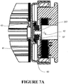
- An example of such a configuration is illustrated in Figures 7A to 7C .
- the stator comprises an axle 257, and the bearing element 57 is positioned on the axle 257.
- the bearing element 57 is received in a ball component 40, and the ball 40 is received in a socket 41 mounted to, or integrally formed with, the rotor 50.
- Angular movement can be accommodated by sliding contact between the ball and the socket.
- Contact surfaces of the ball and the socket are curved with a centre of curvature 42 that is at or near to the centre of the magnetic plane of the motor.
- the effect of misalignment between the stator 20 and the axis 6 of the rotor 50 on the air gap can be reduced or minimized by positioning the pivot centre 42 of the ball and socket joint near to the centre of the magnetic centre-plane of the motor.
- the pivot centre 42 is within a small distance of the magnetic plane of the motor.
- the distance between the pivot centre 42 and the magnetic plane of the motor is less than about 20% of the axial length of the stator core 21.
- the distance between the pivot centre 42 and the magnetic plane of the motor 10 is less than about 10% of the axial length of the stator core 21.
- rotational slip between the ball and the socket may be controlled.
- the rotational slip between the ball and the socket may be controlled by a key and keyway arrangement.
- the key and keyway arrangement can include, for example but without limitation, a key 43 mounted to the ball 40.
- the key 43 can be received in a corresponding keyway in the socket 41.
- the key 43 is a pin or a post.
- the pin or post can have a circular cross-section extending from the curved surface of the ball with a longitudinal axis of the key 43 extending radially outward with respect to the pivot centre 42 of the socket and ball joint.
- rotational coupling between the ball and socket can be achieved by friction generated between the ball and socket or by magnetic attraction between the ball and socket.
- the rotor 50 comprises the axle 56 that extends from the rotor frame 51. Because the rotor 50 is connected to the fan 5 using other members other than a drive shaft, and because the axle 56 does not function as a drive shaft, the axle 56 can be formed in manners unique to the illustrated configuration. For example, because the axle 56 does not function as a drive shaft, the axle 56 does not transmit torque loads. Rather, the rotor axle 56 simply forms an axle about which the rotor 50 can rotate. With no significant torque loading on the axle 56, the axle can be formed of a light weight construction. Moreover, because the axle 56 does not transmit torques, the axle 56 can be mounted in a simplified manner, which will be discussed below.
- the axle 56 can be received in the bearing element 57 that is coupled to the stator 20.
- the axle 56 provides radial support for the rotor 50.
- the axle 56 may also provide axial support.
- axial support can be provided by an axially facing shoulder 58 on the axle 56. Such a configuration is shown in Figure 1 . In the illustrated configuration, the shoulder 58 butts against an axial face of the bearing element 57.
- the stub axle 56 is coupled to the rotor frame 51 via an axial member 59.
- the axial member 59 comprises an outer diameter that decreases from the rotor frame 51 to the stub axle 56.
- the axial member is frusto-conical in shape. Other shapes are possible.
- the increasing diameter of the axial member 59 from the axle 56 to the rotor frame 51 provides sufficient rigidity in the connection of the axle 56 to the rotor frame 51 while allowing for what is a smaller diameter axle 56 than would otherwise be possible.
- the use of the axial member 59 facilitates use of a smaller diameter motor bearing element 57 at the stator 20, which helps to provide a compact motor size.
- At least a portion of the rotor frame 51 is moulded from plastic.
- at least the following portions of the rotor frame 51 are formed of a plastic material: the hub 53, the side wall 54 and the at least one member 55 connecting between the hub 53 and the side wall 54.
- at least these components are integrally moulded from plastic material.
- the rotor axle 56 is integrally moulded with the rotor frame 51.
- the combined rotor frame 51 and rotor axle 56 can be moulded from glass filled polypropylene, PBT (Polybutylene Teraphthalate) or any other suitable engineering plastic material.
- the axle 56 is fabricated separately from the rotor frame 51 and is assembled to the rotor frame 51 in any suitable manner.
- the rotor frame 51 may be over-moulded to the shaft 56 or assembled to the shaft 56 using fasteners or any other suitable means, including but not limited to a splined interface, for example.
- the separate axle 56 may be formed from a material different from the material of the rotor frame 51, for example, steel, ceramic or any suitable engineering plastic. In some configurations comprising an integrally formed rotor frame 51 and shaft 56, the number of components is reduced and the manufacturing/assembly processes are thus improved.
- the rotor axle 56 is received in the bearing element 57 as illustrated in Figure 1 .
- the rotor axle 56 can be hollow or can provide at least a recess 59 that receives the bearing element 57.
- an outer race of the bearing element 57 can be coupled to the recess of the rotor axle 56.
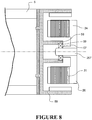
- the bearing 57 can be fitted to an axle 257 of the stator 20.
- the stator axle 257 may be integrally formed with an insulator (not shown in Figure 8 ) that is used to insulate at least a portion of the core 21 of the stator 20.
- stator axle 257 may be supported by the encapsulant that generally encases the stator components. In some configurations, the stator axle 257 may be formed separately and assembled to the stator 20 via the insulator or any other suitable stator component. In some configurations, a resilient material may be provided between the bearing element 57 and that stator axle 257, or between the bearing element 57 and the rotor axle 56, as described earlier with reference to the embodiment of Figure 1 .
- the rotor frame 51 provides an axially and radially stiff but rotationally compliant connection between the hub 53 and the poles of the rotor 50.
- phrases 'axially stiff and radially stiff but rotationally compliant' and 'axially stiff and radially stiff but rotationally flexible' means the rotor frame 51 does not flex when a force of magnitude M is applied axially to the rotor frame 51, and the rotor frame 51 does not flex when a force of the same magnitude M is applied radially or laterally to the rotor frame 51, yet the rotor frame 51 flexes to allow relative rotation between the hub 53 or fan 5 and the rotor poles 52 about the rotational axis 6 of the rotor 50 when a force of the same magnitude M is applied to the rotor frame 51 causing a moment about the rotational axis 6 of the rotor 50.
- the axially and radially stiff but rotationally compliant connection can allow the rotor frame to flex more easily rotationally compared to axially and radially.
- the phrases 'axially stiff and radially stiff but rotationally compliant' and 'axially stiff and radially stiff but rotationally flexible' mean that the rotor frame 51 does not significantly flex axially or radially under normal operating conditions, but does flex to allow relative rotation between the hub 53 or fan 5 and the rotor poles 52 about the rotational axis 6 of the rotor 50 under normal operating conditions.
- the phrases 'rotationally flexible', 'rotationally compliant', and 'low torsional stiffness' mean the rotor frame 51 can flex to allow relative rotation between the rotor hub 53 or fan and the rotor poles 52 about the rotational axis 6 of the rotor 50 under normal operating conditions.
- the rotor frame can flex to allow relative rotation between the rotor poles and the rotor hub of between about 0.2° and about 2° without significant flexing of the rotor frame in the axial and radial directions.
- the rotor frame 51 is used to transfer torque from the rotor poles 52 to the rotor hub 53, for example, the rotor frame 51 can be sufficiently stiff to transfer the torque while remaining flexible enough to absorb vibrations or variations in rotational force encountered during operation.
- the connections between the rotor poles 52 and the rotor hub 53 are sufficiently stiff to transmit forces between about 0.1 Nm and about 0.5 Nm during steady state torque conditions at full operating speeds. In other words, under steady state conditions at full operating speeds, the connections between the rotor poles 52 and the rotor hub 53 preferably are not fully flexed.
- the connections between the rotor poles 52 and the rotor hub 53 are sufficiently stiff to transmit forces between about 0.1 Nm and about 0.5 Nm during steady state torque conditions at full operating speeds and can allow relative rotation between the rotor poles and the rotor hub of between about 0.2° and about 2° without significant flexing of the rotor frame in the axial and radial directions.
- the axially and radially stiff but rotationally compliant connection is provided by a plurality of spokes of the rotor frame 51.
- the spokes can be positioned between the hub 53 of the rotor frame 51 and the rotor poles 52 can be supported by the rotor frame 51.
- the rotor frame 51 comprises connecting members 55 (e.g., spokes) extending from the rotor hub 53 to the circumferential side wall 54.
- each spoke 55 has an axial depth greater than its circumferential thickness and a radial length many times the axial depth.
- each spoke 55 and the number of spokes 55 provide a connection between the rotor poles 52 and the rotor hub 53 that is radially and axially stiff while remaining generally rotationally compliant.
- An axial depth of each spoke 55 and the number of spokes 55 are such that the spokes 55 do not significantly deform axially or significantly buckle radially under normal operating conditions so that the rotor frame 51 is radially and axially stiff under normal operating conditions.
- the spokes 55 provide a connection between the rotor poles 52 and the rotor hub 53 that is rotationally flexible or compliant under normal operating conditions.
- the spokes 55 provide relatively low torsional stiffness between the rotor poles 52 and the rotor hub 53. Therefore, the spokes 55 provide an axially stiff and radially stiff yet rotationally compliant connection as defined above.
- one or more of the spokes 55 can be configured with contoured configurations that facilitate tailoring of the flexibility such that certain portions of the spokes 55 can be more flexible than other portions. Accordingly, one or more of the spokes 55 can be shaped and configured to tune the response. In some configurations, one or more of the spokes 55 can be shaped and configured to reduce resonance that can be caused by pulsations or the like in rotational speeds of the motor 10 and/or the fan 5.
- each spoke 55 generally comprises a cross-section that provides a desired level of axial (e.g., bending in an axial direction), radial (e.g., compressive and/or tensile) and rotational (e.g., bending in a circumferential direction) stiffness.
- axial e.g., bending in an axial direction
- radial e.g., compressive and/or tensile
- rotational e.g., bending in a circumferential direction
- a cross-section comprising a larger axial depth compared to the circumferential (lateral) thickness may be provided for a portion of the length of the spoke 55.
- an axially stiff and radially stiff yet rotationally compliant connection can be provided in any suitable manner.
- spokes 55 arranged to be axially spaced apart at the rotor hub 53 provide an axially stiff rotor frame 51 yet, depending on a cross-section of each spoke 55, the spokes 55 also can provide low rotational stiffness. Therefore, in some configurations, the spokes 55 may comprise an axial depth equal to or less than the circumferential thickness.
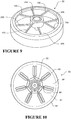
- An example of a spoke arrangement providing an axially and radially stiff yet rotationally compliant connection is illustrated in Figure 9 . As illustrated, the spokes 155 of a first set of spokes can be axially spaced from the spokes 255 of a second set of spokes. In other words, the first set of spokes 155 can intersect the rotor hub 53 at a different axial location relative to the second set of spokes 255.
- the spokes 55 may not extend from the rotor hub 53 radially.
- the spokes may extend from the rotor hub at an angle relative to the radial direction.
- the spokes may extend from the rotor hub in a curved manner relative to the radial direction such that the rotational compliance is dependent on the rotational direction of the rotor 50.
- spokes should be considered to be spokes that are described as radial spokes, as per the definition of the term 'radial' defined above, unless otherwise apparent from the context of the claims or arguments to the contrary.
- the low torsional (i.e., rotational) stiffness between the rotor poles 52 and the rotor hub 53 attenuate torsional vibrations (e.g., torque ripple) and reduce or eliminate transmission of the torsional vibrations from the rotor poles 52 to the rotor hub 53.
- torsional vibrations e.g., torque ripple
- torsional vibrations that are transmitted to a load coupled to the rotor hub 53 can be attenuated or reduced compared to a rotor that is rotationally stiff such as, for example, a rotor that comprises a disc or stiff diaphragm extending between the hub and the circumferential side wall.
- the axial depth of each spoke 55 decreases with increasing distance from the rotor hub 53.
- the axial depth of each spoke 55 at or adjacent to the rotor hub 53 is at least three times the circumferential thickness while the axial depth of each spoke 55 at or adjacent to the side wall 54 is only at least twice the circumferential thickness.
- the radial length of each spoke 55 is at least four times the axial depth of the spoke 55 at or adjacent to the rotor hub 53.
- each spoke 55 comprises a cross-section that comprises a depth (i.e., in an axial direction) greater than the circumferential thickness. In some such configurations, at least a portion of the radial length of the spoke 55 comprises a cross-section that comprises a depth greater than the circumferential thickness. In some configurations, the cross-section extends along the radial length of the spoke by a distance of at least four to five times the axial depth of the cross-section.
- the load e.g., the fan 5
- the load e.g., the fan 5
- the load may be rigidly fixed to the rotor hub 53.
- the load e.g., the fan
- the load may be integrally formed with the rotor hub 53 or integrally formed with the rotor 50 at a location radially within the spokes 55.
- the rotor 50 and the fan 5 can have complementary interfaces to connect the two components together.
- the complementary interfaces can comprise, for example but without limitation, a keyed connection, a bayonet-type connection, or a splined connection.
- the connection between the rotor 50 and the fan 5 may omit any resilient connection because resiliency or compliance is provided in the rotor frame 51, for example but without limitation.
- the rotor frame 51 can comprise an axially and radially stiff yet rotationally compliant connection between the rotor hub 53 and the rotor poles that comprises spokes that extend generally axially.
- the axially and radially stiff yet generally rotationally compliant connection comprises a plurality of spokes 65 positioned between the rotor hub 53 and the rotor poles that are supported by side wall 54 of the rotor frame 51.
- the spokes 65 extend in an axial direction.
- the rotor frame 51 comprises a disc or circular end wall or end frame 66, a circumferential side wall 54 that supports the rotor poles 52 outside the stator poles, and the axially extending spokes 65 that extend between the disc 66 and the circumferential side wall 54.
- the end wall 66 may be cone shaped, dish shaped, or include or comprise generally rigid spokes that extend from the hub 53 to an annular ring or the circumferential side wall 54 with the axial spokes 65 extending between the annular ring or circumferential side wall 54 and the rotor poles 52.
- each spoke 65 has a radial depth greater than a circumferential thickness and an axial length greater than the radial depth.
- the radial depth of each spoke 65 can be at least twice the circumferential thickness while the axial length of each spoke 65 can be at least twice the radial depth. Due to the geometry and the number of spokes 65, the spokes 65 provide a connection that is radially and axially stiff while remaining rotationally compliant. In some configurations, the spokes 65 do not significantly buckle axially or deform laterally or in a radial direction with respect to the rotational axis of the rotor 50 under normal operating conditions.
- the spokes 65 provide a connection between the rotor poles 52 and the rotor hub 53 that is rotationally flexible or compliant under normal operating conditions.
- the spokes 65 provide a relatively low torsional stiffness between the side wall 54 and, therefore the magnet poles 52, and the rotor hub 53.
- the fan 5 may be integrally formed with the rotor frame 51 at any radial location from the centre of the rotor 50 to the outer perimeter of the rotor 50 because the compliant connection, which can comprise the spokes 65, extends axially from the perimeter of the end wall 66.
- the fan 5 can be coupled to the rotor 50 inboard of the spokes 55, 65.
- the spokes 55, 56 are interposed between the fan 5 and the magnet poles 52 of the rotor 50.
- the fan 5 can be somewhat isolated from the magnet poles 52 by the spokes 55, 56.
- Each spoke 65 can comprise a cross-section that provides a desired level of axial (e.g., compressive and/or tensile), radial (e.g., bending in a radial direction) and rotational (e.g., bending in a circumferential direction) stiffness.
- axial e.g., compressive and/or tensile
- radial e.g., bending in a radial direction
- rotational e.g., bending in a circumferential direction
- a cross-section comprising a larger radial depth compared to the circumferential thickness may be provided for at least a portion of the full length of the spoke 65.
- the plurality of spokes 55, 65 comprises an odd number of spokes or a prime number of spokes.
- the inventors currently believe that an odd or prime number of spokes 55, 65 can help reduce or eliminate vibrational harmonics. Accordingly, the inventors currently believe that the odd or prime number of spokes 55, 65 can reduce or eliminate vibrations that transfer from the rotor poles 52 to the rotor hub 53.
- each spoke 55 of the rotor 50 may have at least one surface that is tilted at an angle relative to an axial plane defined through the motor that intersects a longitudinal axis of the spoke.
- at least a portion of a leading edge of the spoke i.e., the surface that faces the direction of rotation
- one or a plurality of spokes 55 are sized and configured to generate a substantially axial flow of air toward or away from the stator 20. In some configurations, all of the spokes 55 are sized and configured to generate a substantially axial flow of air.
- one or more spoke 65 of the rotor 50 may be oriented at an angle to the radial direction of the rotor 50 such that the one or more spoke 65 can operate as a type of fan blade.
- each spoke 65 of the rotor 50 may have at least one surface that is tilted at an angle relative to an axial plane defined through the motor that intersects a longitudinal axis of the spoke.
- At least a portion of a leading edge of at least one spoke 65 is inclined relative to an axially extending plane that intersects the spoke 65 such that at least one spoke 65 can operate as a type of fan blade.
- one or a plurality of spokes 65 are sized and configured to generate a substantially radial flow of air toward or away from the stator 20.
- all of the spokes 65 are sized and configured to generate a substantially radial flow of air.
- the end wall 66 may comprise holes or apertures to allow air flow through the end wall 66 to improve cooling of the motor 10.
- the holes or apertures are generally aligned or overlapping with holes, apertures or openings in the end of the fan 5.
- the disc or end wall 66 may comprise ribs for strengthening the disc. In some such configurations, the ribs may also assist with directing a flow of air toward one or more component of the motor.
- the plurality of spokes 55, 65 may be over-moulded or co-moulded with another material different from the material used in the construction of the rotor frame 51 to achieve a desired balance between axial, radial and torsional stiffness.
- the spokes 55, 65 can comprise a material embedded into or over-moulded onto the rotor frame 51, which rotor frame 51 can be plastic, to achieve desired axial, radial and torsional stiffness.
- one or more spoke 55, 65 may comprise an embedded metal strip, for example but without limitation.
- the rotor frame 51 can comprise a rotational stop that generally limits an extent to which the rotor poles 52 can rotate relative to the rotor hub 53 and/or fan 5.
- a rotational stop may comprise one or more substantially rigid member or members extending outwardly from the rotor hub 53.
- the one or more substantially rigid member may be generally axially aligned with and located between two adjacent spokes, for example but without limitation. The one or more substantially rigid member can limit relative rotation between the rotor poles 52 and the rotor hub 53 by contacting one or more of the two adjacent spokes 55.
- the rotor frame 51 of the rotor 50 illustrated in Figure 10 comprises stop members 85 that are located between adjacent spokes 55.
- a single stop member 85 is positioned between adjacent spokes 55.
- Relative rotation between the rotor hub 53 and the rotor poles 52, which are located outside the outer ends of the spokes 55, is limited by contact between the stop members 85 and at least one of the adjacent spokes 55.
- relative rotation is limited by contact between the stop members 85 and at least one of the adjacent spokes 55 at a contact area 86.
- one or more of the members 85 extend inwardly from an outer end of the adjacent spokes 55.
- This arrangement allows a base 87 of the members 85 to be broader than if the stop members 85 extended from the rotor hub 53 at the inner end of the spokes 55.
- the broad base 87 of the stop members 85 makes the stop members 85 more rigid in the circumferential direction than the spokes 55, for example but without limitation.
- One or more stop member 85 is a cantilever extending inward from the rotor frame 51. In some configurations, one or more stop member 85 is a cantilever extending inward from the rotor frame 51 from the vicinity of the outer end of the spokes 55. In some configurations, the stop members 85 can extend outwardly from the rotor hub 53. The radial position of the contact area 86 provided by the stop members 85, and the distance between the stop member 85 and the adjacent spokes 55 adjacent to the contact area 86, can be chosen to achieve a desired limit to the amount of relative rotation between the rotor poles 52 and the load (e.g., the fan 5) that is coupled to the rotor 50.
- the load e.g., the fan 5
- one or more stop member 85 may be axially spaced from the spokes 55.
- the one or more stop member 85 may be positioned to contact a shoulder formed on an inner side of the circumferential wall 54.
- one or more stop member 85 may be axially spaced from the spokes 55 yet be positioned to contact a shoulder formed on the rotor hub 53.
- the one or more stop member 85 can be axially spaced from the one or more spokes 55 yet be configured to contact a feature formed on an end wall of the rotor 50 (e.g., a circular or dish shaped end of the rotor 50).
- the stop member 85 can be connected to the side wall 54 while the end wall is connected to the rotor hub 53 and vice versa.
- Each of these configurations enables the stop member 85 to limit the degree to which the rotor hub 53 deflects relative to magnetic poles 52 and forms means for limiting rotational displacement of the magnetic poles 52 relative to the rotor hub 53.
- the rotor 50 and the 5 fan may comprise complementary features that limit the degree of relative rotational movement between the rotor poles 52 and the rotor hub 53 and/or the fan 5.
- the fan 5 may comprise a member projecting axially to contact a complementary radial surface on the rotor frame 51 to limit the relative rotation between the rotor poles 52 and the fan 5.
- the rotor 50 or the fan 5 comprises a projection that is received in an aperture or opening or recess in the other of the fan 5 or the rotor 50.
- An outer dimension of the aperture can be larger than a corresponding outer dimension of the projection such that the projection can move toward at least one side of the aperture a predetermined amount.
- the relative movement can accommodate a desired degree of relative rotation between the rotor poles 52 and the fan 5.
- Contact between the projection and the side of the aperture or opening or recess limits the amount of relative rotation between the rotor poles 52 and the fan 5 and/or the rotor hub 53.
- an axially and radially stiff yet rotationally compliant connection can be used to connect the rotor poles 52 to the load (e.g., the fan 5) that is connected to the rotor 50.
- the rotor frame 51 comprises a projection 70.
- the projection 70 is generally cylindrical.
- the projection 70 extends from the area of the rotor hub 53 or a central portion of the rotor frame 51.
- the projection 70 is generally coaxial with the rotational axis 6 of the rotor 50.
- the fan 5 can comprise a complementary component, recess or aperture 4 to engage or receive the projection 70.
- the projection 70 can fit within the recess 4 to secure the rotor 50 to the fan 5 in a radial direction.
- the connection between the projection 70 and the recess 4 can allow relative rotation between the fan 5 and the rotor 50.
- the rotor frame 51 can comprise at least one protrusion 71 that extends from the rotor frame 51 to be received in an aperture 3 of the fan 5.
- at least one pair of the projection 70 and the recess 4 and/or the protrusion 71 and the aperture 3 can be reversed.
- a resilient member 72 can be positioned between the fan 5 and the rotor 50. In some configurations, the resilient member 72 can connect the fan 5 to the rotor 50. In some configurations, the resilient member 72 can be fitted to the protrusion 71. When the rotor 50 is assembled to the fan 5, the resilient member 72 can be located in the aperture 3 and the protrusion 71 can be received in a bore of the resilient member 72.
- the protrusions 71 and corresponding apertures 3 can be spaced radially from the projection 70 so that the protrusion 71, the resilient member 72 and the aperture 3 couple the fan 5 and the rotor 50 such that the fan 5 rotates with the rotor 50 while the resiliency of the resilient member 72 provides rotational compliance between the fan 5 and the rotor 50.
- the fan 5 may comprise a projection that can be received in a recess in the rotor frame 51.
- the projection of the fan 5 may be cylindrical while the recess has a complementary shape.
- the fan 5 may comprise a protrusion or protrusions with resilient members that can be received in complementary apertures formed in the rotor frame 51.
- the rotor50 comprises the projection or recess and the fan 5 comprises the other one of the projection or recess, and the fan 5 and the rotor 50 are coupled together by a resilient member or members spaced radially from the projection.
- a resilient member can be radially spaced from the projection and can be bonded between the rotor frame 51 and the fan 5 to resiliently couple the fan 5 and the rotor 50 together for rotation.
- the projection 70 comprises a generally cylindrical wall that extends from the rotor frame 51 or the fan 5.
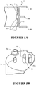
- the projection 70 comprises curved segments 70A that are circumferentially spaced apart with each segment sharing a common centre of curvature to allow relative rotation between the fan 5 and the rotor 51, as illustrated in Figure 5B .
- the projection can be segmented (e.g. see Figure 5B ) and the complementary recess 4 may comprise radially extending shoulders that provide stops to act on radial surfaces 75 defined by each of the segments 70A to define a limit to the amount of relative rotation between the rotor 51 and the fan 5.
- Any other suitable features to limit the amount of relative rotation between the rotor poles 52 and the fan can be provided to the rotor 50 and/or the fan 5.
- one or more of the protrusions 71 may have a larger size than the other protrusions 71 and the resilient member 72 may not be provided to the larger protrusion.
- one of the protrusions 71 without a resilient member may be located in an aperture of a smaller size so that contact between the protrusion 71 and the smaller sized aperture limits the amount of rotational movement allowed by the other protrusions 71, which are fitted with the resilient members 72.
- a resilient member 74 may be provided between one or more of the circumferentially facing surfaces 75 of the segments 70A of the projection 70 and a corresponding facing surface 76 of the recess to provide rotational compliance between the fan 5 and the rotor 50. This arrangement is illustrated in Figure 5C .
- the resilient member 74 can be provided in addition to, or as an alternative to, the protrusions and apertures 71, 3 described above.
- a circumferential space 78 between a shoulder 77 of recess 4 and a facing shoulder 75 of a segment 70A may be smaller than the circumferential space between a shoulder 76 of the recess and a shoulder 75A of the segment 70A where a resilient member 74 is located so that faces 77 and 75 can butt together to limit the amount of relative rotation between the load (e.g., the fan 5) and the rotor poles 52 for a predetermined amount of elastic deformation of the resilient member 74.
- the load e.g., the fan 5
- the resilient member 72 may comprise an axial facing shoulder to provide resiliency between the fan 5 and the rotor 50 in an axial direction.
- axial facing surfaces of the rotor frame 51 and the fan 5 can contact to render an axial connection between the fan 5 and the rotor 50 both axially and radially stiff.
- the resilient member 72 may be assembled over the protrusion 71 or may be over-moulded onto the protrusion 71. In some configurations, there is a plurality of protrusions 71. In some configurations, there is an odd number or prime number of protrusions 71.
- the illustrated protrusions 71 are posts.
- the protrusions 71 may be formed as one or more radially or laterally facing surface or shoulder that is provided to the rotor frame 51 and/or fan 5.
- the protrusion may be formed as a radial rib, for example but without limitation.
- the illustrated rotor 50 can comprise a ring of magnetisable material 52.
- the ring of magnetisable material can be connected to or suitably attached to the rotor frame 51.
- the rotor frame 51 can be plastic.
- the ring of magnetisable material can be magnetised to provide a series of inwardly facing magnet poles 52 of alternating plurality at an inside surface 80 of the ring 52.
- the ring 52 has flux paths from each magnet pole to adjacent magnet poles without departing from the outside surface 81 of the ring 52.
- the magnetisation is such that the majority of magnetic flux between poles of the inside surface 80 of the ring 52 does not exit the ring 52 but passes from pole to pole inside the material of the ring 52 as illustrated in the enlarged view of a part of the magnetic ring 52.
- the maximum flux density on the outside diameter of the ring 52 of magnetised material is less than 50milliTesla.
- the ring 52 may be formed from a single body of material. In some such configurations, the body of material may be pre-formed as a ring and later assembled to the rotor frame 51. In some configurations, the rotor frame 51 may be moulded around or onto the preformed ring. In some configurations, the ring 52 may be moulded from a mouldable magnetisable material in one step and the rotor frame 51 may be moulded around or onto the preformed ring 52 in another step. In some configurations, the ring 52 may be moulded from a mouldable magnetisable material onto a plastic rotor frame 51 that was previously formed or moulded. In some configurations, the ring 52 may be co-moulded with the rotor frame 51, which can be plastic in some such configurations.
- a mouldable magnetisable material can be a plastic loaded with magnetisable particles.
- the magnetisable particles may be, for example, ferrite.
- the magnetisable particles may be of the rare-earth type.
- the plastic may be a binder.
- the plastic may be, for example but without limitation, nylon.
- the ring of magnetisable material may be isotropic with the particles oriented randomly. In some configurations, the ring of magnetisable material may be anisotropic with the particles aligned during moulding in accordance with the intended or desired magnetisation.
- the ring 52 may be formed in multiple components.
- the components could be joined together to form the ring 52 prior to assembly with the rotor frame 51, or prior to over-moulding with the rotor frame 51.
- the components could be assembled individually to the rotor frame 51 to thereby form the ring 52.
- the component could be brought together to form the ring 52 in a mould and the rotor frame 51 can be moulded around or to the components of the ring 52 to hold them together as a ring 52.
- the rotor 50 may not have any magnetically permeable backing member outside the magnetisable ring. In some such configurations, for example, due to the preponderance of internal flux return paths the motor 10 may achieve adequate performance without any steel backing ring positioned outside of or behind the magnet ring 52.
- the rotor 50 may have a magnetically permeable backing member, such as a steel ring, positioned outside of or behind the magnet ring 52.
- the backing member may provide structural stiffness as well as a magnetic flux path.
- the rotor 50 is for a motor 10 of a size suitable for driving the cross flow fan 5 in the HVAC air-conditioning unit.
- the rotor 50 may be between about 25mm and about 115mm in outside diameter.
- the magnet ring internal diameter may be between about 20mm and about 110mm, or between about 50mm and about 100mm, or about 80mm.
- the magnet ring thickness may be between about 4mm and about 15mm or between about 6mm and about 10mm or about 8mm.
- the magnet ring depth may be between about 3mm and about 50mm or between about 5mm and about 25mm or about 10mm.
- the magnet ring may be magnetised to have between 6 and 36 poles, or between 8 and 24 poles, or about 12 poles.
Landscapes
- Engineering & Computer Science (AREA)
- Power Engineering (AREA)
- Mechanical Engineering (AREA)
- General Engineering & Computer Science (AREA)
- Connection Of Motors, Electrical Generators, Mechanical Devices, And The Like (AREA)
- Motor Or Generator Frames (AREA)
- Iron Core Of Rotating Electric Machines (AREA)
Claims (15)
- Motor (10), umfassend:einen Stator (20), umfassend einen ringförmigen Kern (21), Statorpole, die sich aus dem ringförmigen Kern erstrecken, und Wicklungsstränge (23), die auf die Statorpole gewickelt sind; undeinen Rotor (50), umfassend:Rotorpole (52), die den Enden der Statorpole zugewandt sind, eine Rotorachse (56), die sich axial aus dem Rotor zu einer Innenseite des ringförmigen Kerns erstreckt, und nur ein Lagerelement (57), das zwischen der Rotorachse und dem Stator radial innerhalb des ringförmigen Kerns angeordnet ist, um den Rotor rotational mit dem Stator zu koppeln;der Stator ferner umfassend:
ein Lagerortungselement (30), das das Lagerelement radial und axial innerhalb des ringförmigen Kerns montiert, einen Isolator (22), der Oberflächen der Statorpole bedeckt, wobei die Wicklungen über den Isolator auf die Statorpole gewickelt sind und wobei das Lagerortungselement mit dem Isolator einstückig ausgebildet ist, und einer nachgiebigen Halterung (33), die zwischen dem Lagerelement (57) und dem Lagerortungselement (30) oder zwischen der Rotorachse (56) und dem Lagerelement (57) angeordnet ist, um einen Versatz zwischen dem Stator und den Rotorachsen zu ermöglichen. - Motor (10), umfassend:einen Stator (20), umfassend einen ringförmigen Kern (21), Statorpole, die sich aus dem ringförmigen Kern erstrecken, und Wicklungsstränge (23), die auf die Statorpole gewickelt sind; undeinen Rotor (50), umfassend:Rotorpole (52), die den Enden der Statorpole zugewandt sind, eine Rotorachse (56), die sich axial aus dem Rotor zu einer Innenseite des ringförmigen Kerns erstreckt, und nur ein Lagerelement (57), das den Rotor rotational mit dem Stator koppelt, wobei das Lagerelement radial innerhalb des ringförmigen Kerns angeordnet ist und ein sphärisches Lager umfasst, das zwischen der Rotorachse und dem Stator angeordnet ist, um einen Winkelversatz zwischen der Rotorachse und der Statorachse zu ermöglichen;der Stator ferner umfassend:
ein Lagerortungselement (30), das das Lagerelement radial und axial innerhalb des ringförmigen Kerns montiert, und einen Isolator (22), der Oberflächen der Statorpole bedeckt, wobei die Wicklungen über den Isolator auf die Statorpole gewickelt sind und wobei das Lagerortungselement mit dem Isolator einstückig ausgebildet ist. - Motor (10) nach Anspruch 1, wobei die nachgiebige Halterung (33) eine Elastomermuffe oder Kautschukmuffe ist, die eine elastische Halterung für das Lagerelement (57) bereitstellt.
- Motor (10) nach einem der vorhergehenden Ansprüche, wobei das Lagerelement (57) axial an oder nahe einer magnetischen Mittelebene des Motors gelegen ist.
- Motor (10) nach Anspruch 4, wobei der Abstand zwischen einem axialen Mittelpunkt des Lagerelements (57) und der magnetischen Mittelebene des Motors weniger als etwa 20 % der Axiallänge des ringförmigen Kerns (21) beträgt.
- Motor (10) nach Anspruch 1, wobei die nachgiebige Halterung (33) ein Kugelgelenk ist, das eine Kugelkomponente (40) umfasst, die in eine Fassung (41) eingesetzt ist.
- Motor (10) nach Anspruch 1 oder Anspruch 2, wobei das Lagerortungselement (30) eine radial nach innen zugewandte Oberfläche (32) oder Oberflächen und eine axial zugewandte Oberfläche (31) umfasst, um das Lagerelement (57) radial und axial zu montieren.
- Motor (10) nach Anspruch 7, wobei der Motor eine Einkapselung (20) umfasst, die den ringförmigen Kern (21), die Wicklungsstränge (23) und das Lagerortungselement (30) einkapselt, wobei die Einkapselung das Lagerortungselement starr trägt.
- Motor (10) nach einem der vorhergehenden Ansprüche, wobei die Rotorachse (56) keine Antriebswelle ist.
- Motor (10) nach Anspruch 2, ferner umfassend eine nachgiebige Halterung (33), die zwischen dem Lagerelement (57) und dem Lagerortungselement (30) oder zwischen der Rotorachse (56) und dem Lagerelement (57) angeordnet ist.
- Motor (10) nach Anspruch 1, wobei das Lagerelement (57) ein sphärisches Lager umfasst.
- Motor nach einem der vorhergehenden Ansprüche, wobei der Motor ein Außenrotormotor ist und der Rotor (50) einen Rotorrahmen (51) umfasst, der eine Nabe (53) an seiner Rotationsachse aufweist und der die Rotorpole trägt (52), wobei der Rotorrahmen einen gewissen Grad an axialer, radialer und rotationaler Nachgiebigkeit aufweist, wobei der Grad der rotationalen Nachgiebigkeit viel größer ist als der Grad der axialen sowie der radialen Nachgiebigkeit.
- Motor nach Anspruch 12, wobei der Rotorrahmen (51) mehrere Speichen (55) umfasst, die sich zwischen der Nabe (53) und den Rotorpolen (52) erstrecken, wobei sich wenigstens eine Speiche hinsichtlich der Rotationsachse des Rotors (50) nach außen erstreckt.
- Motor nach Anspruch 13, wobei die Steifheit der wenigstens einen Speiche (55) in Axialrichtung größer ist als in Umfangsrichtung.
- Motor nach Anspruch 14, wobei die wenigstens eine Speiche (55) ein Segment umfasst, dass einen Querschnitt aufweist, dessen Axialtiefe größer als eine Umfangsdicke ist, die sich entlang der Speiche über einen Abstand erstreckt, der größer als die Axialtiefe ist.
Applications Claiming Priority (2)
| Application Number | Priority Date | Filing Date | Title |
|---|---|---|---|
| US201261740738P | 2012-12-21 | 2012-12-21 | |
| PCT/NZ2013/000242 WO2014098625A1 (en) | 2012-12-21 | 2013-12-19 | A motor |
Publications (3)
| Publication Number | Publication Date |
|---|---|
| EP2936659A1 EP2936659A1 (de) | 2015-10-28 |
| EP2936659A4 EP2936659A4 (de) | 2016-08-10 |
| EP2936659B1 true EP2936659B1 (de) | 2020-09-30 |
Family
ID=50973821
Family Applications (1)
| Application Number | Title | Priority Date | Filing Date |
|---|---|---|---|
| EP13864222.8A Active EP2936659B1 (de) | 2012-12-21 | 2013-12-19 | Motor |
Country Status (5)
| Country | Link |
|---|---|
| US (2) | US9685840B2 (de) |
| EP (1) | EP2936659B1 (de) |
| CN (2) | CN104170219B (de) |
| AU (2) | AU2013364501B2 (de) |
| WO (1) | WO2014098625A1 (de) |
Families Citing this family (55)
| Publication number | Priority date | Publication date | Assignee | Title |
|---|---|---|---|---|
| JP6414224B2 (ja) * | 2014-08-29 | 2018-10-31 | 工機ホールディングス株式会社 | 電動作業機 |
| US10523081B2 (en) * | 2014-11-25 | 2019-12-31 | Black & Decker Inc. | Brushless motor for a power tool |
| FR3034585B1 (fr) * | 2015-03-30 | 2017-05-12 | Moteurs Leroy-Somer | Liaison entre un arbre de machine electrique et un reducteur |
| CN106313333B (zh) * | 2015-06-30 | 2021-06-18 | 南京德朔实业有限公司 | 切割工具 |
| JP6172234B2 (ja) * | 2015-10-15 | 2017-08-02 | ダイキン工業株式会社 | 電動機および送風装置 |
| US10326323B2 (en) | 2015-12-11 | 2019-06-18 | Whirlpool Corporation | Multi-component rotor for an electric motor of an appliance |
| US10704180B2 (en) | 2016-09-22 | 2020-07-07 | Whirlpool Corporation | Reinforcing cap for a tub rear wall of an appliance |
| US10400817B2 (en) | 2016-11-22 | 2019-09-03 | Woodward, Inc. | Radial bearing device |
| IT201700018552A1 (it) * | 2017-02-20 | 2018-08-20 | Elica Spa | Convogliatore radiale per cappe aspiranti |
| DE102017206759A1 (de) * | 2017-04-21 | 2018-10-25 | Efficient Energy Gmbh | Rotor für einen elektromotor mit speziell geformtem rückschlusselement und verfahren zur herstellung |
| DE102017206762A1 (de) * | 2017-04-21 | 2018-10-25 | Efficient Energy Gmbh | Rotor für einen elektromotor mit wärmeabschirmender beschichtung und verfahren zur herstellung |
| US10693336B2 (en) | 2017-06-02 | 2020-06-23 | Whirlpool Corporation | Winding configuration electric motor |
| US11843334B2 (en) | 2017-07-13 | 2023-12-12 | Denso Corporation | Rotating electrical machine |
| CN114552828B (zh) | 2017-07-21 | 2023-08-15 | 株式会社电装 | 旋转电机 |
| CN107701518B (zh) * | 2017-10-19 | 2024-03-29 | 珠海格力电器股份有限公司 | 贯流风轮安装结构、风道组件及具有贯流风轮的装置 |
| DE112018006699T5 (de) | 2017-12-28 | 2020-09-10 | Denso Corporation | Rotierende elektrische Maschine |
| JP6922868B2 (ja) | 2017-12-28 | 2021-08-18 | 株式会社デンソー | 回転電機システム |
| JP6939750B2 (ja) | 2017-12-28 | 2021-09-22 | 株式会社デンソー | 回転電機 |
| JP7006541B2 (ja) * | 2017-12-28 | 2022-01-24 | 株式会社デンソー | 回転電機 |
| CN111512519B (zh) | 2017-12-28 | 2022-10-11 | 株式会社电装 | 旋转电机 |
| CN111566904B (zh) | 2017-12-28 | 2023-04-28 | 株式会社电装 | 旋转电机 |
| WO2019148833A1 (zh) * | 2018-02-05 | 2019-08-08 | 中山大洋电机股份有限公司 | 一种贯流风轮与电机的安装结构 |
| CN108377060B (zh) * | 2018-02-28 | 2024-04-26 | 浙江京惠机电有限公司 | 一种工业电机 |
| CN108599451B (zh) * | 2018-06-27 | 2024-01-26 | 沈阳工业大学 | 一种电动汽车用轮毂电机的强化传热结构 |
| KR102656561B1 (ko) * | 2018-10-01 | 2024-04-12 | 엘지이노텍 주식회사 | 모터 |
| US11005337B2 (en) * | 2018-10-23 | 2021-05-11 | Atieva, Inc. | Removable differential for an active core electric motor |
| US11025133B2 (en) * | 2019-02-20 | 2021-06-01 | Dana Automotive Systems Group, Llc | Electric motor brake |
| US11670977B2 (en) | 2019-04-24 | 2023-06-06 | Black & Decker Inc. | Outer rotor brushless motor stator mount |
| CN110571957B (zh) * | 2019-09-06 | 2024-06-25 | 重庆东渝中能实业有限公司 | 一种柔性电机 |
| JP6978705B2 (ja) * | 2019-09-30 | 2021-12-08 | ダイキン工業株式会社 | ファン組立体及び空気調和機 |
| US11757330B2 (en) | 2019-12-19 | 2023-09-12 | Black & Decker, Inc. | Canned outer-rotor brushless motor for a power tool |
| US11437900B2 (en) | 2019-12-19 | 2022-09-06 | Black & Decker Inc. | Modular outer-rotor brushless motor for a power tool |
| CN113692690B (zh) | 2020-03-05 | 2024-08-23 | 株式会社电装 | 旋转电机 |
| IT202000014392A1 (it) * | 2020-06-16 | 2021-12-16 | Baruffaldi Spa | Rotore esterno in materiale plastomagnetico |
| DE102020209500A1 (de) | 2020-07-28 | 2022-02-03 | Brose Fahrzeugteile Se & Co. Kommanditgesellschaft, Bamberg | Antriebsvorrichtung mit einem bürstenlosen Elektromotor |
| CN112615510B (zh) * | 2020-12-21 | 2025-01-10 | 江门市胜思特电器有限公司 | 往复式磁定位电机 |
| US12104602B2 (en) * | 2021-02-18 | 2024-10-01 | Levitronix Gmbh | Cross-flow fan |
| HUE069980T2 (hu) | 2021-06-24 | 2025-04-28 | Eta Green Power Ltd | Rotor elektromos géphez |
| GB2608167B (en) * | 2021-06-24 | 2023-11-22 | Eta Green Power Ltd | Rotor for an electric machine |
| GB2614454B (en) * | 2021-06-24 | 2024-06-05 | Eta Green Power Ltd | Rotor for an electric machine |
| GB2608165B (en) * | 2021-06-24 | 2024-04-24 | Eta Green Power Ltd | Rotor for an electric machine |
| US11791679B2 (en) | 2021-08-19 | 2023-10-17 | Nidec Motor Corporation | Spoked rotor having deflectable magnet-retaining spokes |
| USD1029714S1 (en) | 2021-08-19 | 2024-06-04 | Nidec Motor Corporation | Spoked rotor |
| WO2023023307A1 (en) * | 2021-08-20 | 2023-02-23 | Milwaukee Electric Tool Corporation | Electric motor |
| EP4181353A1 (de) * | 2021-11-10 | 2023-05-17 | Hamilton Sundstrand Corporation | Verbundmagnetträger |
| US12176794B2 (en) | 2021-11-19 | 2024-12-24 | Black & Decker Inc. | Outer-rotor brushless motor for a power tool |
| DE102022117562A1 (de) * | 2022-07-14 | 2024-01-25 | Dr. Ing. H.C. F. Porsche Aktiengesellschaft | Rotoreinrichtung für eine elektrische Maschine und insbesondere für einen Fahrantrieb eines Kraftfahrzeugs sowie Verfahren zur Herstellung einer Rotoreinrichtung |
| CN115296457B (zh) * | 2022-07-30 | 2025-12-30 | 广东美的暖通设备有限公司 | 转子结构、电机和压缩机 |
| US12691741B2 (en) | 2022-08-23 | 2026-07-28 | Black & Decker Inc. | Control module for high power motor |
| DE102022127293B4 (de) | 2022-10-18 | 2024-09-19 | Audi Aktiengesellschaft | Polabdeckung für einen Elektromotor |
| US12689249B2 (en) | 2022-12-02 | 2026-07-21 | Milwaukee Electric Tool Corporation | Electric motor |
| WO2025167302A1 (zh) * | 2024-02-05 | 2025-08-14 | 广东威灵电机制造有限公司 | 电机、风机组件和暖通设备 |
| CN119244559A (zh) * | 2024-08-22 | 2025-01-03 | 佛山市南海区绿智电机设备有限公司 | 一种带减震结构的外转子贯流风轮及其装配工艺 |
| WO2026099939A1 (ja) * | 2024-11-06 | 2026-05-15 | 日産自動車株式会社 | 回転電機 |
| CN121461678B (zh) * | 2025-12-31 | 2026-05-26 | 浙江金龙电机股份有限公司 | 一种具有降噪功能的电动叉车异步电机 |
Citations (3)
| Publication number | Priority date | Publication date | Assignee | Title |
|---|---|---|---|---|
| DE3629049A1 (de) * | 1986-08-27 | 1988-03-03 | Mulfingen Elektrobau Ebm | Stator fuer einen aussenlaeufermotor |
| US6488412B1 (en) * | 1999-09-17 | 2002-12-03 | Sunonwealth Electric Machine Industry Co., Ltd. | Bearing sleeve assemblies for heat dissipating fan motors |
| US20090309438A1 (en) * | 2008-06-12 | 2009-12-17 | Alex Horng | Motor Structure |
Family Cites Families (63)
| Publication number | Priority date | Publication date | Assignee | Title |
|---|---|---|---|---|
| US3474272A (en) | 1968-05-09 | 1969-10-21 | Mesur Matic Electronics Corp | Wobbling rotor step motor with stator coils and pole arrangement |
| JPS62104452A (ja) | 1985-10-30 | 1987-05-14 | Daikin Ind Ltd | モ−タ一体形フアン |
| JPH01159497A (ja) | 1987-09-04 | 1989-06-22 | Daikin Ind Ltd | ファン装置 |
| JPH01129743A (ja) | 1987-11-12 | 1989-05-23 | Daikin Ind Ltd | ファン装置の組立方法 |
| JPH01290999A (ja) | 1988-05-14 | 1989-11-22 | Daikin Ind Ltd | ファン装置 |
| JPH0245697A (ja) | 1988-08-05 | 1990-02-15 | Daikin Ind Ltd | ファン装置 |
| JPH02197236A (ja) | 1989-01-26 | 1990-08-03 | Daikin Ind Ltd | 回転電力機 |
| JPH02207192A (ja) | 1989-02-06 | 1990-08-16 | Daikin Ind Ltd | ファン装置 |
| JPH037045A (ja) | 1989-06-01 | 1991-01-14 | Daikin Ind Ltd | 回転電力機の製造方法 |
| JPH0311965A (ja) | 1989-06-08 | 1991-01-21 | Daikin Ind Ltd | 回転電力機 |
| JP3011965B2 (ja) | 1990-05-22 | 2000-02-21 | 本田技研工業株式会社 | パルス幅変調回路の故障診断装置 |
| JPH0475707A (ja) | 1990-07-17 | 1992-03-10 | Kawasaki Steel Corp | 粗度維持性の優れた冷間または調質圧延用作業ロール |
| US5402024A (en) * | 1992-04-06 | 1995-03-28 | Matsushita Electric Industrial Co., Ltd. | Rotor for a permanent-magnet motor |
| JP3007045B2 (ja) | 1996-07-09 | 2000-02-07 | 株式会社北浦製作所 | 連結送水管設備 |
| JPH1129743A (ja) | 1997-07-09 | 1999-02-02 | Hitachi Chem Co Ltd | シリカ系被膜形成用塗布液、その製造法及びシリカ系被膜 |
| JPH1159497A (ja) | 1997-08-12 | 1999-03-02 | Nissan Motor Co Ltd | 車体側面構造 |
| US5944497A (en) * | 1997-11-25 | 1999-08-31 | Siemens Canada Limited | Fan assembly having an air directing member to cool a motor |
| JP2001078382A (ja) | 1999-06-30 | 2001-03-23 | Asmo Co Ltd | ブラシレスモータ及び車両用空調装置 |
| CN1101614C (zh) | 1999-07-02 | 2003-02-12 | 建准电机工业股份有限公司 | 改良转子定位构造的电动机 |
| US6362554B1 (en) * | 1999-07-29 | 2002-03-26 | Encap Motor Corporation | Stator assembly |
| JP3513654B2 (ja) | 2000-01-14 | 2004-03-31 | 日本電産シバウラ株式会社 | 軸流ファン |
| JP3480443B2 (ja) | 2000-11-29 | 2003-12-22 | ダイキン工業株式会社 | ファン装置 |
| WO2002044568A1 (en) | 2000-11-29 | 2002-06-06 | Daikin Industries, Ltd. | Fan device |
| CN1193480C (zh) | 2001-06-21 | 2005-03-16 | 许俊甫 | 一种电动机 |
| JP4639539B2 (ja) * | 2001-07-03 | 2011-02-23 | いすゞ自動車株式会社 | フライホイール |
| JP4552381B2 (ja) | 2003-02-17 | 2010-09-29 | ダイキン工業株式会社 | 送風装置、送風機構、空気調和装置および送風装置の製造方法 |
| JP4618292B2 (ja) | 2003-03-03 | 2011-01-26 | ダイキン工業株式会社 | 送風装置および空気調和装置 |
| JP4075707B2 (ja) * | 2003-03-03 | 2008-04-16 | ダイキン工業株式会社 | 送風装置および空気調和装置 |
| JP3966246B2 (ja) | 2003-07-04 | 2007-08-29 | ダイキン工業株式会社 | 空気調和装置の室内機の送風ユニット |
| JP3966258B2 (ja) | 2003-08-25 | 2007-08-29 | ダイキン工業株式会社 | 空調室内機のファンの製造方法 |
| JP3903971B2 (ja) | 2003-08-25 | 2007-04-11 | ダイキン工業株式会社 | 空気調和機の室内機 |
| JP2005069580A (ja) | 2003-08-25 | 2005-03-17 | Daikin Ind Ltd | 空調室内機のファンおよびこれを備えた送風装置 |
| US7048495B2 (en) * | 2003-11-19 | 2006-05-23 | Itt Manufacturing Enterprises, Inc. | Rotating machine having a shaft including an integral bearing surface |
| DE102004050373A1 (de) * | 2004-10-15 | 2006-04-27 | Minebea Co., Ltd. | Statoranordnung für eine elektrische Maschine und Elektromotor |
| CN1988334A (zh) | 2005-12-20 | 2007-06-27 | 乐金电子(天津)电器有限公司 | 空调器用送风装置 |
| JP4816380B2 (ja) | 2006-09-29 | 2011-11-16 | ダイキン工業株式会社 | ファンモータユニット、及びそのファンモータユニットを備えた空調室内機 |
| JP2008086184A (ja) | 2006-09-29 | 2008-04-10 | Daikin Ind Ltd | アウタロータ型モータ |
| JP4952174B2 (ja) | 2006-09-29 | 2012-06-13 | ダイキン工業株式会社 | ファンモータユニット、及びそのファンモータユニットを備えた空調室内機 |
| JP4952173B2 (ja) | 2006-09-29 | 2012-06-13 | ダイキン工業株式会社 | 空調室内機 |
| JP4946320B2 (ja) | 2006-09-29 | 2012-06-06 | ダイキン工業株式会社 | 空調室内機 |
| JP2008099520A (ja) | 2006-10-16 | 2008-04-24 | Daikin Ind Ltd | アウタロータ型モータ |
| JP4175417B2 (ja) | 2006-11-06 | 2008-11-05 | ダイキン工業株式会社 | アウターロータモータ及びその製造方法 |
| JP4487998B2 (ja) | 2006-11-20 | 2010-06-23 | ダイキン工業株式会社 | 空気調和機の室内機 |
| JP2008261598A (ja) | 2007-04-13 | 2008-10-30 | Daikin Ind Ltd | ファンモータ支持部材ならびに空気調和機 |
| CN101350540A (zh) | 2007-07-20 | 2009-01-21 | 乐金电子(天津)电器有限公司 | 分体壁挂式空调器室内机的风扇电机 |
| JP4465380B2 (ja) * | 2007-11-06 | 2010-05-19 | シナノケンシ株式会社 | アウターロータ型モータ |
| CN201142613Y (zh) * | 2008-01-02 | 2008-10-29 | 湘潭电机股份有限公司 | 一种散热筋直驱永磁同步单轴承风力发电机 |
| KR101474425B1 (ko) * | 2008-01-21 | 2014-12-22 | 엘지전자 주식회사 | 냉장고용 팬 조립체 |
| JP5195042B2 (ja) | 2008-05-30 | 2013-05-08 | ダイキン工業株式会社 | 空調室内機 |
| CN201307790Y (zh) | 2008-11-04 | 2009-09-09 | 珠海格力电器股份有限公司 | 电机转子及送风系统 |
| WO2010058666A1 (ja) | 2008-11-20 | 2010-05-27 | ダイキン工業株式会社 | 空気調和機 |
| CN201466819U (zh) | 2009-07-16 | 2010-05-12 | 珠海格力电器股份有限公司 | 电机转子及电机 |
| WO2011032201A1 (en) * | 2009-09-21 | 2011-03-24 | Soderberg Rod F | A matrix material comprising magnetic particles for use in hybrid and electric vehicles |
| KR101074935B1 (ko) * | 2009-11-04 | 2011-10-18 | 뉴모텍(주) | 냉기 송풍용 팬 모터 |
| IT1397782B1 (it) | 2010-01-15 | 2013-01-24 | Gate Srl | Rotore a magneti permanenti per un motore elettrico brushless in corrente continua |
| JP5501015B2 (ja) * | 2010-02-08 | 2014-05-21 | 山洋電気株式会社 | 電動ファン |
| CA2792437C (en) * | 2010-03-15 | 2016-08-02 | Ebm-Papst St. Georgen Gmbh & Co. Kg | External rotor motor |
| CN102270900A (zh) * | 2010-06-03 | 2011-12-07 | 北京天道新源风电科技股份有限公司 | 兆瓦级直驱低速永磁风力发电机 |
| US9484779B2 (en) * | 2011-04-04 | 2016-11-01 | Columbia Power Technologies, Inc. | Mechanical assembly for maintaining an air gap between a stator and rotor in an electro-mechanical energy converter |
| DE102011007813A1 (de) * | 2011-04-20 | 2012-10-25 | Hauni Maschinenbau Ag | Speichenrad |
| TWI437799B (zh) * | 2011-07-21 | 2014-05-11 | Sunonwealth Electr Mach Ind Co | 封膠定子 |
| DE102011081384B4 (de) | 2011-08-23 | 2017-05-04 | Robert Bosch Gmbh | Verfahren und Vorrichtung zur Abstandsbestimmung für ein Fahrzeug |
| WO2013184961A1 (en) * | 2012-06-06 | 2013-12-12 | Nidec Motor Corporation | Motor having spoked outer rotor with spaced apart pole segments |
-
2013
- 2013-12-19 EP EP13864222.8A patent/EP2936659B1/de active Active
- 2013-12-19 CN CN201380002695.0A patent/CN104170219B/zh active Active
- 2013-12-19 US US14/135,299 patent/US9685840B2/en active Active
- 2013-12-19 WO PCT/NZ2013/000242 patent/WO2014098625A1/en not_active Ceased
- 2013-12-19 AU AU2013364501A patent/AU2013364501B2/en not_active Ceased
- 2013-12-19 CN CN201710799067.XA patent/CN107546883B/zh active Active
-
2017
- 2017-06-01 US US15/611,526 patent/US10193416B2/en active Active
- 2017-09-05 AU AU2017225017A patent/AU2017225017B2/en not_active Ceased
Patent Citations (3)
| Publication number | Priority date | Publication date | Assignee | Title |
|---|---|---|---|---|
| DE3629049A1 (de) * | 1986-08-27 | 1988-03-03 | Mulfingen Elektrobau Ebm | Stator fuer einen aussenlaeufermotor |
| US6488412B1 (en) * | 1999-09-17 | 2002-12-03 | Sunonwealth Electric Machine Industry Co., Ltd. | Bearing sleeve assemblies for heat dissipating fan motors |
| US20090309438A1 (en) * | 2008-06-12 | 2009-12-17 | Alex Horng | Motor Structure |
Also Published As
| Publication number | Publication date |
|---|---|
| EP2936659A1 (de) | 2015-10-28 |
| US9685840B2 (en) | 2017-06-20 |
| US20140175912A1 (en) | 2014-06-26 |
| EP2936659A4 (de) | 2016-08-10 |
| AU2013364501B2 (en) | 2017-09-14 |
| CN107546883A (zh) | 2018-01-05 |
| US20170271945A1 (en) | 2017-09-21 |
| CN104170219B (zh) | 2017-10-24 |
| WO2014098625A1 (en) | 2014-06-26 |
| US10193416B2 (en) | 2019-01-29 |
| CN104170219A (zh) | 2014-11-26 |
| AU2013364501A1 (en) | 2015-07-02 |
| AU2017225017A1 (en) | 2017-09-28 |
| CN107546883B (zh) | 2021-02-26 |
| AU2017225017B2 (en) | 2019-01-17 |
Similar Documents
| Publication | Publication Date | Title |
|---|---|---|
| AU2017225017B2 (en) | A Motor | |
| JP5231790B2 (ja) | モータ回転子及びモータ | |
| US8035269B2 (en) | Electric machine | |
| US20130140964A1 (en) | Motor for electric power steering device | |
| CN105122596A (zh) | 具有通过弯曲载体保持的单区段的单区段转子和制造方法 | |
| JP2016129473A (ja) | モータ | |
| CN110417135B (zh) | 定子单元、马达以及送风装置 | |
| CN112737169A (zh) | 电机转子结构及电机 | |
| CN107508445B (zh) | 一种外转子无刷电机 | |
| CN208123095U (zh) | 轴流风扇 | |
| KR20180054087A (ko) | 스테이터 일체형 차량용 팬모터 | |
| JP2000166146A (ja) | アウターロータ型回転子とアウターロータ型モータ | |
| US11699937B2 (en) | Blower | |
| US12015326B2 (en) | Motor and electric device | |
| CN113472108A (zh) | 转子和马达 | |
| CN219779878U (zh) | 一种外转子电机 | |
| JP2003324929A (ja) | モータ | |
| JP7178547B2 (ja) | ブラシレスモータ | |
| JP4348606B2 (ja) | アキシャルギャップ型電動機 | |
| JP6530530B2 (ja) | ブラシレスモータ | |
| KR20100039163A (ko) | 팬 구동용 모터 | |
| KR20160149044A (ko) | 브러시리스 진동모터 | |
| KR102686655B1 (ko) | 팬 모터와 이를 포함하는 전자기기 | |
| CN218449645U (zh) | 马达和电气产品 | |
| WO2024224802A1 (ja) | モールドモータ |
Legal Events
| Date | Code | Title | Description |
|---|---|---|---|
| PUAI | Public reference made under article 153(3) epc to a published international application that has entered the european phase |
Free format text: ORIGINAL CODE: 0009012 |
|
| 17P | Request for examination filed |
Effective date: 20150708 |
|
| AK | Designated contracting states |
Kind code of ref document: A1 Designated state(s): AL AT BE BG CH CY CZ DE DK EE ES FI FR GB GR HR HU IE IS IT LI LT LU LV MC MK MT NL NO PL PT RO RS SE SI SK SM TR |
|
| AX | Request for extension of the european patent |
Extension state: BA ME |
|
| DAX | Request for extension of the european patent (deleted) | ||
| A4 | Supplementary search report drawn up and despatched |
Effective date: 20160713 |
|
| RIC1 | Information provided on ipc code assigned before grant |
Ipc: F04D 17/04 20060101ALI20160707BHEP Ipc: H02K 5/173 20060101ALI20160707BHEP Ipc: H02K 1/22 20060101ALI20160707BHEP Ipc: H02K 1/04 20060101ALI20160707BHEP Ipc: H02K 1/18 20060101ALI20160707BHEP Ipc: H02K 1/30 20060101ALI20160707BHEP Ipc: H02K 7/14 20060101ALN20160707BHEP Ipc: H02K 7/08 20060101ALI20160707BHEP Ipc: H02K 5/16 20060101AFI20160707BHEP Ipc: H02K 21/22 20060101ALN20160707BHEP Ipc: F04D 25/06 20060101ALI20160707BHEP Ipc: H02K 5/167 20060101ALI20160707BHEP Ipc: H02K 1/27 20060101ALI20160707BHEP Ipc: H02K 3/52 20060101ALI20160707BHEP |
|
| STAA | Information on the status of an ep patent application or granted ep patent |
Free format text: STATUS: EXAMINATION IS IN PROGRESS |
|
| 17Q | First examination report despatched |
Effective date: 20170626 |
|
| 17Q | First examination report despatched |
Effective date: 20171213 |
|
| GRAP | Despatch of communication of intention to grant a patent |
Free format text: ORIGINAL CODE: EPIDOSNIGR1 |
|
| STAA | Information on the status of an ep patent application or granted ep patent |
Free format text: STATUS: GRANT OF PATENT IS INTENDED |
|
| RIC1 | Information provided on ipc code assigned before grant |
Ipc: H02K 1/18 20060101ALI20200407BHEP Ipc: H02K 5/16 20060101AFI20200407BHEP Ipc: H02K 3/52 20060101ALI20200407BHEP Ipc: F04D 17/04 20060101ALI20200407BHEP Ipc: H02K 1/04 20060101ALI20200407BHEP Ipc: H02K 1/27 20060101ALI20200407BHEP Ipc: F04D 25/06 20060101ALI20200407BHEP Ipc: H02K 5/167 20060101ALI20200407BHEP Ipc: H02K 5/173 20060101ALI20200407BHEP Ipc: H02K 1/30 20060101ALI20200407BHEP Ipc: H02K 1/22 20060101ALI20200407BHEP Ipc: H02K 7/14 20060101ALN20200407BHEP Ipc: H02K 7/08 20060101ALI20200407BHEP Ipc: H02K 21/22 20060101ALN20200407BHEP |
|
| INTG | Intention to grant announced |
Effective date: 20200428 |
|
| GRAS | Grant fee paid |
Free format text: ORIGINAL CODE: EPIDOSNIGR3 |
|
| GRAA | (expected) grant |
Free format text: ORIGINAL CODE: 0009210 |
|
| STAA | Information on the status of an ep patent application or granted ep patent |
Free format text: STATUS: THE PATENT HAS BEEN GRANTED |
|
| AK | Designated contracting states |
Kind code of ref document: B1 Designated state(s): AL AT BE BG CH CY CZ DE DK EE ES FI FR GB GR HR HU IE IS IT LI LT LU LV MC MK MT NL NO PL PT RO RS SE SI SK SM TR |
|
| REG | Reference to a national code |
Ref country code: GB Ref legal event code: FG4D Ref country code: CH Ref legal event code: EP |
|
| REG | Reference to a national code |
Ref country code: AT Ref legal event code: REF Ref document number: 1319810 Country of ref document: AT Kind code of ref document: T Effective date: 20201015 |
|
| REG | Reference to a national code |
Ref country code: DE Ref legal event code: R096 Ref document number: 602013072996 Country of ref document: DE |
|
| REG | Reference to a national code |
Ref country code: IE Ref legal event code: FG4D |
|
| PG25 | Lapsed in a contracting state [announced via postgrant information from national office to epo] |
Ref country code: FI Free format text: LAPSE BECAUSE OF FAILURE TO SUBMIT A TRANSLATION OF THE DESCRIPTION OR TO PAY THE FEE WITHIN THE PRESCRIBED TIME-LIMIT Effective date: 20200930 Ref country code: HR Free format text: LAPSE BECAUSE OF FAILURE TO SUBMIT A TRANSLATION OF THE DESCRIPTION OR TO PAY THE FEE WITHIN THE PRESCRIBED TIME-LIMIT Effective date: 20200930 Ref country code: NO Free format text: LAPSE BECAUSE OF FAILURE TO SUBMIT A TRANSLATION OF THE DESCRIPTION OR TO PAY THE FEE WITHIN THE PRESCRIBED TIME-LIMIT Effective date: 20201230 Ref country code: GR Free format text: LAPSE BECAUSE OF FAILURE TO SUBMIT A TRANSLATION OF THE DESCRIPTION OR TO PAY THE FEE WITHIN THE PRESCRIBED TIME-LIMIT Effective date: 20201231 Ref country code: SE Free format text: LAPSE BECAUSE OF FAILURE TO SUBMIT A TRANSLATION OF THE DESCRIPTION OR TO PAY THE FEE WITHIN THE PRESCRIBED TIME-LIMIT Effective date: 20200930 Ref country code: BG Free format text: LAPSE BECAUSE OF FAILURE TO SUBMIT A TRANSLATION OF THE DESCRIPTION OR TO PAY THE FEE WITHIN THE PRESCRIBED TIME-LIMIT Effective date: 20201230 |
|
| REG | Reference to a national code |
Ref country code: AT Ref legal event code: MK05 Ref document number: 1319810 Country of ref document: AT Kind code of ref document: T Effective date: 20200930 |
|
| PG25 | Lapsed in a contracting state [announced via postgrant information from national office to epo] |
Ref country code: LV Free format text: LAPSE BECAUSE OF FAILURE TO SUBMIT A TRANSLATION OF THE DESCRIPTION OR TO PAY THE FEE WITHIN THE PRESCRIBED TIME-LIMIT Effective date: 20200930 Ref country code: RS Free format text: LAPSE BECAUSE OF FAILURE TO SUBMIT A TRANSLATION OF THE DESCRIPTION OR TO PAY THE FEE WITHIN THE PRESCRIBED TIME-LIMIT Effective date: 20200930 |
|
| REG | Reference to a national code |
Ref country code: NL Ref legal event code: MP Effective date: 20200930 |
|
| REG | Reference to a national code |
Ref country code: LT Ref legal event code: MG4D |
|
| PG25 | Lapsed in a contracting state [announced via postgrant information from national office to epo] |
Ref country code: NL Free format text: LAPSE BECAUSE OF FAILURE TO SUBMIT A TRANSLATION OF THE DESCRIPTION OR TO PAY THE FEE WITHIN THE PRESCRIBED TIME-LIMIT Effective date: 20200930 Ref country code: LT Free format text: LAPSE BECAUSE OF FAILURE TO SUBMIT A TRANSLATION OF THE DESCRIPTION OR TO PAY THE FEE WITHIN THE PRESCRIBED TIME-LIMIT Effective date: 20200930 Ref country code: PT Free format text: LAPSE BECAUSE OF FAILURE TO SUBMIT A TRANSLATION OF THE DESCRIPTION OR TO PAY THE FEE WITHIN THE PRESCRIBED TIME-LIMIT Effective date: 20210201 Ref country code: RO Free format text: LAPSE BECAUSE OF FAILURE TO SUBMIT A TRANSLATION OF THE DESCRIPTION OR TO PAY THE FEE WITHIN THE PRESCRIBED TIME-LIMIT Effective date: 20200930 Ref country code: SM Free format text: LAPSE BECAUSE OF FAILURE TO SUBMIT A TRANSLATION OF THE DESCRIPTION OR TO PAY THE FEE WITHIN THE PRESCRIBED TIME-LIMIT Effective date: 20200930 Ref country code: EE Free format text: LAPSE BECAUSE OF FAILURE TO SUBMIT A TRANSLATION OF THE DESCRIPTION OR TO PAY THE FEE WITHIN THE PRESCRIBED TIME-LIMIT Effective date: 20200930 Ref country code: CZ Free format text: LAPSE BECAUSE OF FAILURE TO SUBMIT A TRANSLATION OF THE DESCRIPTION OR TO PAY THE FEE WITHIN THE PRESCRIBED TIME-LIMIT Effective date: 20200930 |
|
| PG25 | Lapsed in a contracting state [announced via postgrant information from national office to epo] |
Ref country code: AT Free format text: LAPSE BECAUSE OF FAILURE TO SUBMIT A TRANSLATION OF THE DESCRIPTION OR TO PAY THE FEE WITHIN THE PRESCRIBED TIME-LIMIT Effective date: 20200930 Ref country code: AL Free format text: LAPSE BECAUSE OF FAILURE TO SUBMIT A TRANSLATION OF THE DESCRIPTION OR TO PAY THE FEE WITHIN THE PRESCRIBED TIME-LIMIT Effective date: 20200930 Ref country code: ES Free format text: LAPSE BECAUSE OF FAILURE TO SUBMIT A TRANSLATION OF THE DESCRIPTION OR TO PAY THE FEE WITHIN THE PRESCRIBED TIME-LIMIT Effective date: 20200930 Ref country code: IS Free format text: LAPSE BECAUSE OF FAILURE TO SUBMIT A TRANSLATION OF THE DESCRIPTION OR TO PAY THE FEE WITHIN THE PRESCRIBED TIME-LIMIT Effective date: 20210130 Ref country code: PL Free format text: LAPSE BECAUSE OF FAILURE TO SUBMIT A TRANSLATION OF THE DESCRIPTION OR TO PAY THE FEE WITHIN THE PRESCRIBED TIME-LIMIT Effective date: 20200930 |
|
| PG25 | Lapsed in a contracting state [announced via postgrant information from national office to epo] |
Ref country code: SK Free format text: LAPSE BECAUSE OF FAILURE TO SUBMIT A TRANSLATION OF THE DESCRIPTION OR TO PAY THE FEE WITHIN THE PRESCRIBED TIME-LIMIT Effective date: 20200930 |
|
| REG | Reference to a national code |
Ref country code: DE Ref legal event code: R097 Ref document number: 602013072996 Country of ref document: DE |
|
| REG | Reference to a national code |
Ref country code: CH Ref legal event code: PL |
|
| PLBE | No opposition filed within time limit |
Free format text: ORIGINAL CODE: 0009261 |
|
| STAA | Information on the status of an ep patent application or granted ep patent |
Free format text: STATUS: NO OPPOSITION FILED WITHIN TIME LIMIT |
|
| PG25 | Lapsed in a contracting state [announced via postgrant information from national office to epo] |
Ref country code: MC Free format text: LAPSE BECAUSE OF FAILURE TO SUBMIT A TRANSLATION OF THE DESCRIPTION OR TO PAY THE FEE WITHIN THE PRESCRIBED TIME-LIMIT Effective date: 20200930 Ref country code: DK Free format text: LAPSE BECAUSE OF FAILURE TO SUBMIT A TRANSLATION OF THE DESCRIPTION OR TO PAY THE FEE WITHIN THE PRESCRIBED TIME-LIMIT Effective date: 20200930 |
|
| REG | Reference to a national code |
Ref country code: BE Ref legal event code: MM Effective date: 20201231 |
|
| 26N | No opposition filed |
Effective date: 20210701 |
|
| PG25 | Lapsed in a contracting state [announced via postgrant information from national office to epo] |
Ref country code: IT Free format text: LAPSE BECAUSE OF FAILURE TO SUBMIT A TRANSLATION OF THE DESCRIPTION OR TO PAY THE FEE WITHIN THE PRESCRIBED TIME-LIMIT Effective date: 20200930 Ref country code: IE Free format text: LAPSE BECAUSE OF NON-PAYMENT OF DUE FEES Effective date: 20201219 Ref country code: LU Free format text: LAPSE BECAUSE OF NON-PAYMENT OF DUE FEES Effective date: 20201219 |
|
| PG25 | Lapsed in a contracting state [announced via postgrant information from national office to epo] |
Ref country code: LI Free format text: LAPSE BECAUSE OF NON-PAYMENT OF DUE FEES Effective date: 20201231 Ref country code: SI Free format text: LAPSE BECAUSE OF FAILURE TO SUBMIT A TRANSLATION OF THE DESCRIPTION OR TO PAY THE FEE WITHIN THE PRESCRIBED TIME-LIMIT Effective date: 20200930 Ref country code: CH Free format text: LAPSE BECAUSE OF NON-PAYMENT OF DUE FEES Effective date: 20201231 |
|
| PG25 | Lapsed in a contracting state [announced via postgrant information from national office to epo] |
Ref country code: IS Free format text: LAPSE BECAUSE OF FAILURE TO SUBMIT A TRANSLATION OF THE DESCRIPTION OR TO PAY THE FEE WITHIN THE PRESCRIBED TIME-LIMIT Effective date: 20210130 Ref country code: TR Free format text: LAPSE BECAUSE OF FAILURE TO SUBMIT A TRANSLATION OF THE DESCRIPTION OR TO PAY THE FEE WITHIN THE PRESCRIBED TIME-LIMIT Effective date: 20200930 Ref country code: MT Free format text: LAPSE BECAUSE OF FAILURE TO SUBMIT A TRANSLATION OF THE DESCRIPTION OR TO PAY THE FEE WITHIN THE PRESCRIBED TIME-LIMIT Effective date: 20200930 Ref country code: CY Free format text: LAPSE BECAUSE OF FAILURE TO SUBMIT A TRANSLATION OF THE DESCRIPTION OR TO PAY THE FEE WITHIN THE PRESCRIBED TIME-LIMIT Effective date: 20200930 |
|
| PG25 | Lapsed in a contracting state [announced via postgrant information from national office to epo] |
Ref country code: MK Free format text: LAPSE BECAUSE OF FAILURE TO SUBMIT A TRANSLATION OF THE DESCRIPTION OR TO PAY THE FEE WITHIN THE PRESCRIBED TIME-LIMIT Effective date: 20200930 |
|
| PG25 | Lapsed in a contracting state [announced via postgrant information from national office to epo] |
Ref country code: BE Free format text: LAPSE BECAUSE OF NON-PAYMENT OF DUE FEES Effective date: 20201231 |
|
| REG | Reference to a national code |
Ref country code: FR Ref legal event code: PLFP Year of fee payment: 10 |
|
| P01 | Opt-out of the competence of the unified patent court (upc) registered |
Effective date: 20230513 |
|
| PGFP | Annual fee paid to national office [announced via postgrant information from national office to epo] |
Ref country code: DE Payment date: 20241213 Year of fee payment: 12 |
|
| PGFP | Annual fee paid to national office [announced via postgrant information from national office to epo] |
Ref country code: GB Payment date: 20241212 Year of fee payment: 12 |
|
| PGFP | Annual fee paid to national office [announced via postgrant information from national office to epo] |
Ref country code: FR Payment date: 20241227 Year of fee payment: 12 |