EP2083198A2 - Procédé et appareil de commande destinés à la commande d'un faisceau d'entraînement, comprenant une boîte de vitesse double - Google Patents
Procédé et appareil de commande destinés à la commande d'un faisceau d'entraînement, comprenant une boîte de vitesse double Download PDFInfo
- Publication number
- EP2083198A2 EP2083198A2 EP08018976A EP08018976A EP2083198A2 EP 2083198 A2 EP2083198 A2 EP 2083198A2 EP 08018976 A EP08018976 A EP 08018976A EP 08018976 A EP08018976 A EP 08018976A EP 2083198 A2 EP2083198 A2 EP 2083198A2
- Authority
- EP
- European Patent Office
- Prior art keywords
- clutch
- speed
- nmot
- gear
- threshold
- Prior art date
- Legal status (The legal status is an assumption and is not a legal conclusion. Google has not performed a legal analysis and makes no representation as to the accuracy of the status listed.)
- Withdrawn
Links
Images


Classifications
-
- F—MECHANICAL ENGINEERING; LIGHTING; HEATING; WEAPONS; BLASTING
- F16—ENGINEERING ELEMENTS AND UNITS; GENERAL MEASURES FOR PRODUCING AND MAINTAINING EFFECTIVE FUNCTIONING OF MACHINES OR INSTALLATIONS; THERMAL INSULATION IN GENERAL
- F16H—GEARING
- F16H61/00—Control functions within control units of change-speed- or reversing-gearings for conveying rotary motion ; Control of exclusively fluid gearing, friction gearing, gearings with endless flexible members or other particular types of gearing
- F16H61/04—Smoothing ratio shift
- F16H61/0437—Smoothing ratio shift by using electrical signals
-
- B—PERFORMING OPERATIONS; TRANSPORTING
- B60—VEHICLES IN GENERAL
- B60W—CONJOINT CONTROL OF VEHICLE SUB-UNITS OF DIFFERENT TYPE OR DIFFERENT FUNCTION; CONTROL SYSTEMS SPECIALLY ADAPTED FOR HYBRID VEHICLES; ROAD VEHICLE DRIVE CONTROL SYSTEMS FOR PURPOSES NOT RELATED TO THE CONTROL OF A PARTICULAR SUB-UNIT
- B60W10/00—Conjoint control of vehicle sub-units of different type or different function
- B60W10/10—Conjoint control of vehicle sub-units of different type or different function including control of change-speed gearings
- B60W10/11—Stepped gearings
- B60W10/113—Stepped gearings with two input flow paths, e.g. double clutch transmission selection of one of the torque flow paths by the corresponding input clutch
-
- B—PERFORMING OPERATIONS; TRANSPORTING
- B60—VEHICLES IN GENERAL
- B60W—CONJOINT CONTROL OF VEHICLE SUB-UNITS OF DIFFERENT TYPE OR DIFFERENT FUNCTION; CONTROL SYSTEMS SPECIALLY ADAPTED FOR HYBRID VEHICLES; ROAD VEHICLE DRIVE CONTROL SYSTEMS FOR PURPOSES NOT RELATED TO THE CONTROL OF A PARTICULAR SUB-UNIT
- B60W30/00—Purposes of road vehicle drive control systems not related to the control of a particular sub-unit, e.g. of systems using conjoint control of vehicle sub-units
- B60W30/18—Propelling the vehicle
- B60W30/18009—Propelling the vehicle related to particular drive situations
- B60W30/18063—Creeping
-
- B—PERFORMING OPERATIONS; TRANSPORTING
- B60—VEHICLES IN GENERAL
- B60W—CONJOINT CONTROL OF VEHICLE SUB-UNITS OF DIFFERENT TYPE OR DIFFERENT FUNCTION; CONTROL SYSTEMS SPECIALLY ADAPTED FOR HYBRID VEHICLES; ROAD VEHICLE DRIVE CONTROL SYSTEMS FOR PURPOSES NOT RELATED TO THE CONTROL OF A PARTICULAR SUB-UNIT
- B60W30/00—Purposes of road vehicle drive control systems not related to the control of a particular sub-unit, e.g. of systems using conjoint control of vehicle sub-units
- B60W30/18—Propelling the vehicle
- B60W30/18009—Propelling the vehicle related to particular drive situations
- B60W30/181—Preparing for stopping
-
- B—PERFORMING OPERATIONS; TRANSPORTING
- B60—VEHICLES IN GENERAL
- B60W—CONJOINT CONTROL OF VEHICLE SUB-UNITS OF DIFFERENT TYPE OR DIFFERENT FUNCTION; CONTROL SYSTEMS SPECIALLY ADAPTED FOR HYBRID VEHICLES; ROAD VEHICLE DRIVE CONTROL SYSTEMS FOR PURPOSES NOT RELATED TO THE CONTROL OF A PARTICULAR SUB-UNIT
- B60W30/00—Purposes of road vehicle drive control systems not related to the control of a particular sub-unit, e.g. of systems using conjoint control of vehicle sub-units
- B60W30/18—Propelling the vehicle
- B60W30/20—Reducing vibrations in the driveline
-
- F—MECHANICAL ENGINEERING; LIGHTING; HEATING; WEAPONS; BLASTING
- F16—ENGINEERING ELEMENTS AND UNITS; GENERAL MEASURES FOR PRODUCING AND MAINTAINING EFFECTIVE FUNCTIONING OF MACHINES OR INSTALLATIONS; THERMAL INSULATION IN GENERAL
- F16H—GEARING
- F16H61/00—Control functions within control units of change-speed- or reversing-gearings for conveying rotary motion ; Control of exclusively fluid gearing, friction gearing, gearings with endless flexible members or other particular types of gearing
- F16H61/68—Control functions within control units of change-speed- or reversing-gearings for conveying rotary motion ; Control of exclusively fluid gearing, friction gearing, gearings with endless flexible members or other particular types of gearing specially adapted for stepped gearings
- F16H61/684—Control functions within control units of change-speed- or reversing-gearings for conveying rotary motion ; Control of exclusively fluid gearing, friction gearing, gearings with endless flexible members or other particular types of gearing specially adapted for stepped gearings without interruption of drive
- F16H61/688—Control functions within control units of change-speed- or reversing-gearings for conveying rotary motion ; Control of exclusively fluid gearing, friction gearing, gearings with endless flexible members or other particular types of gearing specially adapted for stepped gearings without interruption of drive with two inputs, e.g. selection of one of two torque-flow paths by clutches
-
- B—PERFORMING OPERATIONS; TRANSPORTING
- B60—VEHICLES IN GENERAL
- B60W—CONJOINT CONTROL OF VEHICLE SUB-UNITS OF DIFFERENT TYPE OR DIFFERENT FUNCTION; CONTROL SYSTEMS SPECIALLY ADAPTED FOR HYBRID VEHICLES; ROAD VEHICLE DRIVE CONTROL SYSTEMS FOR PURPOSES NOT RELATED TO THE CONTROL OF A PARTICULAR SUB-UNIT
- B60W2710/00—Output or target parameters relating to a particular sub-units
- B60W2710/06—Combustion engines, Gas turbines
- B60W2710/0644—Engine speed
- B60W2710/065—Idle condition
-
- F—MECHANICAL ENGINEERING; LIGHTING; HEATING; WEAPONS; BLASTING
- F16—ENGINEERING ELEMENTS AND UNITS; GENERAL MEASURES FOR PRODUCING AND MAINTAINING EFFECTIVE FUNCTIONING OF MACHINES OR INSTALLATIONS; THERMAL INSULATION IN GENERAL
- F16D—COUPLINGS FOR TRANSMITTING ROTATION; CLUTCHES; BRAKES
- F16D2500/00—External control of clutches by electric or electronic means
- F16D2500/10—System to be controlled
- F16D2500/108—Gear
- F16D2500/1086—Concentric shafts
-
- F—MECHANICAL ENGINEERING; LIGHTING; HEATING; WEAPONS; BLASTING
- F16—ENGINEERING ELEMENTS AND UNITS; GENERAL MEASURES FOR PRODUCING AND MAINTAINING EFFECTIVE FUNCTIONING OF MACHINES OR INSTALLATIONS; THERMAL INSULATION IN GENERAL
- F16D—COUPLINGS FOR TRANSMITTING ROTATION; CLUTCHES; BRAKES
- F16D2500/00—External control of clutches by electric or electronic means
- F16D2500/30—Signal inputs
- F16D2500/306—Signal inputs from the engine
- F16D2500/3067—Speed of the engine
-
- F—MECHANICAL ENGINEERING; LIGHTING; HEATING; WEAPONS; BLASTING
- F16—ENGINEERING ELEMENTS AND UNITS; GENERAL MEASURES FOR PRODUCING AND MAINTAINING EFFECTIVE FUNCTIONING OF MACHINES OR INSTALLATIONS; THERMAL INSULATION IN GENERAL
- F16D—COUPLINGS FOR TRANSMITTING ROTATION; CLUTCHES; BRAKES
- F16D2500/00—External control of clutches by electric or electronic means
- F16D2500/70—Details about the implementation of the control system
- F16D2500/704—Output parameters from the control unit; Target parameters to be controlled
- F16D2500/70422—Clutch parameters
- F16D2500/70432—From the input shaft
- F16D2500/70436—Input shaft speed
-
- F—MECHANICAL ENGINEERING; LIGHTING; HEATING; WEAPONS; BLASTING
- F16—ENGINEERING ELEMENTS AND UNITS; GENERAL MEASURES FOR PRODUCING AND MAINTAINING EFFECTIVE FUNCTIONING OF MACHINES OR INSTALLATIONS; THERMAL INSULATION IN GENERAL
- F16D—COUPLINGS FOR TRANSMITTING ROTATION; CLUTCHES; BRAKES
- F16D2500/00—External control of clutches by electric or electronic means
- F16D2500/70—Details about the implementation of the control system
- F16D2500/704—Output parameters from the control unit; Target parameters to be controlled
- F16D2500/70452—Engine parameters
- F16D2500/70454—Engine speed
-
- F—MECHANICAL ENGINEERING; LIGHTING; HEATING; WEAPONS; BLASTING
- F16—ENGINEERING ELEMENTS AND UNITS; GENERAL MEASURES FOR PRODUCING AND MAINTAINING EFFECTIVE FUNCTIONING OF MACHINES OR INSTALLATIONS; THERMAL INSULATION IN GENERAL
- F16H—GEARING
- F16H2302/00—Determining the way or trajectory to new ratio, e.g. by determining speed, torque or time parameters for shift transition
-
- F—MECHANICAL ENGINEERING; LIGHTING; HEATING; WEAPONS; BLASTING
- F16—ENGINEERING ELEMENTS AND UNITS; GENERAL MEASURES FOR PRODUCING AND MAINTAINING EFFECTIVE FUNCTIONING OF MACHINES OR INSTALLATIONS; THERMAL INSULATION IN GENERAL
- F16H—GEARING
- F16H2312/00—Driving activities
- F16H2312/02—Driving off
-
- F—MECHANICAL ENGINEERING; LIGHTING; HEATING; WEAPONS; BLASTING
- F16—ENGINEERING ELEMENTS AND UNITS; GENERAL MEASURES FOR PRODUCING AND MAINTAINING EFFECTIVE FUNCTIONING OF MACHINES OR INSTALLATIONS; THERMAL INSULATION IN GENERAL
- F16H—GEARING
- F16H2312/00—Driving activities
- F16H2312/16—Coming to a halt
Definitions
- the invention relates to a method for controlling the drivetrain of a motor vehicle having a dual-clutch transmission with a first partial transmission and a first clutch and a second partial transmission and a second clutch, wherein the drive train with simultaneously engaged in the first partial transmission gear and engaged in the second partial transmission gear and simultaneously operated in the slip operated first clutch and second clutch.
- the invention further relates to a set up for carrying out the method control unit.
- Such a method and such a control unit is known in each case from series-produced motor vehicles.
- the division of the dual-clutch transmission in a first and in the second partial transmission which can be connected independently of each other via the first, respectively second clutch with the drive motor of the drive train, allows a change in the transmission without interruption.
- the drive motor usually drives the motor vehicle initially via the first clutch and the first partial transmission.
- the second gear can already be engaged in the second subtransmission.
- the comfort plays a greater role than other properties, such as a sporty driving.
- the stepping pace range between about 5 and 15 km / h, longitudinal vibrations of the vehicle caused by said circuits or noticeable jerks caused by load changes or vibrations caused by charge changes in the filling of combustion chambers of the drive motor are perceived as disturbing.
- the first and the second clutch are controlled in a coordinated manner so that a rotational speed of the internal combustion engine assumes or retains a predetermined value.
- both clutches are operated in slip, preferably in regulated slip, in order to achieve a desired comfortable driving behavior.
- the engine speed smoothly follows a target rotational speed when driving slowly at a setpoint speed, and without pronounced local rotational speed minima and rotational speed maxima.
- the target speed may be, for example, the idle speed when stopping.
- the engine speed could drop below a target speed, especially at slow speeds in 1st and 2nd gear.
- the low engine speeds of, for example, 700 rpm to 1200 rpm achieved in the invention help to reduce fuel consumption.
- the shows Fig. 1 a drive train 10 of a motor vehicle.
- the drive train 10 has an internal combustion engine 12, a dual-clutch transmission 14 and further transmissions and / or shafts for transmitting power between drive wheels 16, 18 of the motor vehicle and the internal combustion engine 12.
- Such an arrangement is typical for a motor vehicle with front engine and rear-wheel drive.
- the invention is not limited to use with the illustrated driveline 10 and may also be used with front-wheel-drive, four-wheel drive, or transaxle-type rear drives.
- the dual-clutch transmission 14 has a first partial transmission TG1 and a second partial transmission TG2.
- the first partial transmission TG1 provides, in one embodiment, odd-numbered gear ratios such as the first gear, the third gear, and so on, while the second sub-gear TG2 provides the even-numbered gear ratios (aisles) such as the second gear, the fourth gear, and the fourth gear so on.
- Both a main shaft 34 of the first subtransmission TG1 and a main shaft 36 of the second subtransmission TG2 is rotatably connected to the shaft 20.
- the shafts 34 and 36 therefore rotate at the same speed which, when the motor vehicle is traveling straight ahead without slip on the drive wheels 16, 18, depends linearly on the rotational speed of the drive wheels 16, 18 and thus linearly on the travel speed v of the vehicle.
- a control unit 40 controls in the embodiment of FIG. 1 It is understood that instead of a single control unit 40, a composite of a plurality of control units can be used, which in turn are coordinated by a central control unit or communicate with each other via a bus system, to coordinate their individual control interventions in the drive train 10.
- the control unit 40 processes signals Variety of sensors in which reproduce operating parameters of the drive train 10.
- An accelerator pedal angle Wped which is provided by a driver request generator 42 and in which a torque request is represented by the driver, a speed nMot of the crankshaft 30 of the internal combustion engine 12, that of a speed sensor 43 and a vehicle speed v detected by a vehicle speed sensor 44.
- the vehicle speed sensor 44 is implemented in one embodiment as a speed sensor, which detects a rotational speed at the output of the dual-clutch transmission 14, that is to say a rotational speed of one of the shafts 34, 36 or 20.
- a speed signal is detected at one or more of the wheels 16, 18, for example by means of the sensor system of an anti-lock braking system.
- the rotational speed nK1 of the input shaft 28 of the first partial transmission TG1 and the rotational speed nK2 of the input shaft 32 of the second partial transmission TG2 are each a linear function of the vehicle speed v.
- control unit 40 forms control signals S_Mot, S_K1, S_K2, S_TG1 and S_TG2.
- the control signal S_Mot is used to set a torque of the internal combustion engine 12.
- the control signal S_TG1 is used to engage a gear in the first partial transmission TG1 and thus to set its translation.
- the actuating signal S_TG2 is analogous to setting a ratio in the second partial transmission TG2. With the control signal S_K1, the torque flow is controlled via the first clutch K1. Analogously, the torque flow is controlled via the second clutch K2 with the actuating signal S_K2.
- the relationship of the drive signals S_K1, S_K2 with the torque transmitted in each case via each of the two clutches K1, K2 at specific speed differences is preferably in the form of characteristic curves or characteristic diagrams in the control unit 40 stored. This is state of the art.
- the speed differences are also known in the control unit 40 by evaluating the speed values nMot and nK1, nK2.
- Also known is the engine torque which is continuously calculated by the control unit 40 from operating characteristics of the internal combustion engine 12, since modern engine controls determine all control variables on the basis of torque requests, which are calculated, for example, as a function of the accelerator pedal angle Wped.
- control unit 40 determines the direction of the respective transmitted torque and the speed difference and the drive signal S_K1, S_K2, which ultimately maps in the contact pressure of the clutch friction surfaces, the value of the value over each of the two clutches K1, K2 transmitted torque.
- the controller 40 may distribute the torque flow across both clutches K1, K2 in a controlled manner and thus control the direction and magnitude of the resulting total torque flow to match the engine speed nMot by driving both clutches K1, K2 to a set point or set point over time or to set above the travel speed v.
- control unit 40 or a corresponding combination of control units is adapted, in particular programmed, to carry out the method according to the invention or one of its embodiments.
- an implementation is understood to mean a control of the process sequences described here.
- FIG. 2 illustrates the emergence of the aforementioned, disturbing jerks and / or longitudinal vibrations.
- FIG. 2 Gradients of various operating parameters of the drive train 10 from the FIG. 1 in a prior art control of the driveline 10 over time t when the vehicle is stopped.
- the dashed lines 45, 46 and 47 represent, in this order, the rotational speeds nK1_Gang 3 of the input shaft 28 of the subtransmission TG1 in third gear, the rotational speed nK2_Gang 2 of the input shaft 32 of the second subtransmission TG2 in the second gear and the speed nK1_Gang 1 of the input shaft 28 of the first partial transmission TG1 in first gear.
- the solid line 48 represents the associated time profile of the speed nMot.
- each of the three dashed lines 45, 46 and 47 represents the course of the vehicle speed v until the motor vehicle stops at the time t_stop.
- the clutch K2 is open.
- the engine speed nMot corresponds there to the speed nK1_Gang 3.
- the second gear is engaged in the second partial transmission TG2.
- the first clutch K1 is increasingly opened and the clutch K2 increasingly closed, until the time t1, the clutch K1 completely open and the clutch K2 is completely closed.
- the speed nMot accordingly increases with slipping clutches K1, K2 until the time t1, in order subsequently to drop again when the clutch K2 and the open clutch K1 are closed when the vehicle decelerates further.
- the clutch K1 is opened at the time t4. Subsequently, the rotational speed nMot is maintained at a constant value by a known idle speed control.
- the change visible before time t4 in the course 48 of the speed nMot between local speed minima and local speed maxima arises from the fact that the speed of the internal combustion engine 12 between the times t0 and t1 and t2 and t3 is raised at the expense of the kinetic energy of the vehicle.
- the braking effect of the internal combustion engine 12 therefore varies and stimulates the vibrations in the drive train 10, which are reflected in the unwanted longitudinal vibrations of the vehicle.
- the jerk on opening the clutch K1 at time t4 is a disturbance that can excite vibrations or is noticeable as jerk.
- Fig. 3 shows a flowchart as an embodiment of a method according to the invention.
- the drive train 10 is controlled in a known manner.
- the Fig. 2 shown course of the engine speed nMot with the explained maxima and minima.
- BP comfort-oriented control
- f1 BP
- f2 a function f1 (BP)
- f2 an exit from the comfort-oriented control, so that a hysteresis between entry and exit into the comfort-oriented control is possible.
- B is set to 1 when the vehicle is being moved with a low torque demand by the driver, ie with a low pedal angle Wped and low speed in a low gear, for example in first or second gear.
- it is checked whether the accelerator pedal angle Wped is less than a lower threshold value Wped_low and, at the same time, both the engine rpm nMot is less than a threshold value nMot_Grenz and the vehicle speed v is less than a threshold value v_Grenz.
- Typical values are, without the invention being restricted to these values: Wped_Grenz ⁇ 10% of the maximum pedal angle, 500 min -1 ⁇ idle speed ⁇ nMot_Grenz ⁇ (900 min -1 in the plane, 1200 min -1 on the mountain).
- step 60 is repeatedly reached, in which operating parameters BP of the drive train 10 are read in, which are evaluated for deactivating the comfort-oriented control of the drive train presented here.
- B is set to 0 in step 62 when the clutch K1 in first gear or the clutch K2 no longer slips in second gear, so no difference between engine speed nMot and the rotational speed of the input shaft of the associated sub-transmission occurs more, and at the same time Vehicle speed v exceeds a threshold v_Grenz or is above this threshold.
- the threshold value is preferably less than 20 km / h and, in one embodiment, is dependent on the modulation factor MF so that a higher limit value results on the mountain than in the plane.
- B is set to 0 when the driver's torque request Wped exceeds a threshold Wped_Grenz_Zug and the clutch to be engaged no longer slips.
- the threshold value Wped_Grenz_Zug is dependent on the driving speed v and the modulation factor so that it also increases with increasing values of v and / or MF.
- values for Wped_Grenz_Zug are preferably between 50% and 70% of the maximum pedal angle.
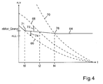
- the vehicle decelerates in third gear.
- the clutch K1 is closed and the clutch K2 is open, wherein the second gear TG2 already the second gear is engaged.
- the rotational speed nMot decreases in proportion to the decrease in the vehicle speed v until nMot reaches a threshold nMot_Grenz at the time t0.
- the speed v in associated closed clutch is proportional to the speed nMot, the proportionality factor is dependent on the translation and thus the engaged gear.
- the dashed curves 66, 68 and 70 represent in this order the speeds nK1_Gang 3 of the input shaft 28 of the subtransmission TG1 in third gear, the speed nK2_Gang 2 of the input shaft 32 of the second subtransmission TG2 in second gear and the speed nK1_Gang 1 of the input shaft 28 of the first subtransmission TG1 in first gear.
- the time profile of the vehicle speed v was brought into line with the course of the engine speed nMot in third gear.
- the curve 66 thus simultaneously represents rotational speed values and driving speed values.
- the threshold nMot_Grenz at point 71 simultaneously represents a speed threshold and a (lower) speed threshold v_Grenz.
- nMot_Grenz From the time t0 of reaching the threshold nMot_Grenz becomes the first Coupling K1 successively opened and the second clutch K2 successively closed.
- the opening of the clutch K1 and the closing of the clutch K2 takes place in a coordinated manner so that the engine speed nMot decreases monotonically decreasing the idle speed nLL of the engine 12 as the target speed.
- the rotational speed nMot is set as an alternative or in addition to interventions in the control of the internal combustion engine 12 by coordinated control of the torque fluxes via both clutches K1, K2.
- the clutch K2 was open and thus transmitted no torque, while the clutch K1 transmits a deceleration vehicle, a sliding torque with which the internal combustion engine 12 is driven by the kinetic energy of the decelerating vehicle.
- the gradual opening of the clutch K1 from the time t0 allows a slip on the clutch K1.
- the parallel gradually closing clutch K2 shifts the transmission of the internal combustion engine 12 driving the shift torque to the clutch K2.
- the engine speed nMot after the time t0 is between values on the second-speed curve 68 and the third-speed curve 66.
- the engine speed nMot is too high for third gear and too low for second gear. That is, the engine speed nMot can be reduced by closing the third-speed clutch K1 and increased by closing the second-speed clutch K2.
- the speed nMot By closing control of one of the two clutches K1, K2, the speed nMot can thus be increased or decreased.
- the control is carried out in one embodiment preferably in a controlled manner.
- the actual value of the engine speed nMot is compared with a desired value and the control deviation S_K1 and S_K2 are formed with which the torque transmission via the clutches K1 and K2 is controlled individually.
- both clutches K1, K2 are controlled from time t0 so that the rotational speed nMot of the internal combustion engine 12 is monotonically decreasing by suitable driving of both clutches K1, K2 and thus converted into the target speed without occurrence of local extremes.
- the speed nMot passes through the curve 68.
- the momentarily closed clutch K2 temporarily transmits the entire shift torque, while the clutch K1 is temporarily fully opened.
- clutch K1 When clutch K1 is engaged, first gear is engaged. From now on, closing the clutch K1 increases nMot- increasing and keeping the clutch K2 closed keeps the engine depressed.
- the engine speed nMot is monotonically reduced to the target speed by corresponding activation of the clutches K1, K2.
- the target speed in the form of the idle speed nLL is reached at time t4, in which the curve 70 intersects the value of the target speed.
- the second clutch K2 In order to prevent the engine speed nMot from falling below the target speed, not only the second clutch K2 but also the first clutch K1 is increasingly opened as it approaches the intersection 76.
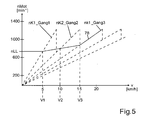
- FIG. 5 shows a transmission map in which linear dependencies of the engine speed nMot on the vehicle speed v are plotted for the various gears of the dual-clutch transmission 14.
- the curve 78 represents the speed nMot of the internal combustion engine 12, which initially corresponds to its idling speed nLL.
- nLL the speed of the internal combustion engine 12
- Both clutches K1, K2 transmit tractive moments of the internal combustion engine, which set the vehicle in motion.
- the engine speed nMot is in this phase by interventions S_mot in the control of the internal combustion engine held a setpoint, which corresponds to one embodiment of the idle speed nLL or slightly higher.
- the speed nMot of the speed nK1_Gang 1 corresponds to the input shaft 28 of the first subtransmission TG1.
- the first clutch K1 can no longer transmit traction torques when the first gear is engaged for speeds v> v1. Instead, it can only transfer pusher moments.
- the clutch K2 initially transmits a tensile torque.
- both clutches K1, K2 are initially operated in slippage as the speed v increases, and the speed nMot of the internal combustion engine 12 is at speeds v> v1 by suitable actuation of the clutches K1, K2 with gears engaged simultaneously in both partial transmissions TG1, TG2 set to a setpoint.
- the adjustment is preferably carried out by a control.
- the clutch K1 transmits a sliding torque in the illustrated course of nMot, while the clutch K2 transmits a traction torque.
- the clutch K1 transmits a traction torque in the course of nMot shown, while the clutch K2 transmits a sliding torque. If the moment of tension predominates, the speed nMot decreases. If the sliding moment prevails, the speed nMot increases.
- the engine speed nMot corresponds to the speed nK1_Gang3 of the input shaft 28 of the first partial transmission TG1, so that no speed difference occurs at the clutch K1.
- the clutch K1 is driven in the illustrated embodiment at this time so that it closes completely at this speed, while the clutch K2 is controlled so that it is completely open. In this case, the complete opening of a clutch does not coincide exactly with the complete closing of the other clutch. It is only essential that at least one of the two clutches K1, K2 is operated in slippage with gears simultaneously engaged in both partial transmissions TG1, TG2, so that the dual-clutch transmission 14th not blocked.
Landscapes
- Engineering & Computer Science (AREA)
- Mechanical Engineering (AREA)
- Transportation (AREA)
- General Engineering & Computer Science (AREA)
- Automation & Control Theory (AREA)
- Chemical & Material Sciences (AREA)
- Combustion & Propulsion (AREA)
- Hydraulic Clutches, Magnetic Clutches, Fluid Clutches, And Fluid Joints (AREA)
- Control Of Transmission Device (AREA)
- Mechanical Operated Clutches (AREA)
Applications Claiming Priority (1)
| Application Number | Priority Date | Filing Date | Title |
|---|---|---|---|
| DE102008006194A DE102008006194A1 (de) | 2008-01-26 | 2008-01-26 | Verfahren und Steuergerät zur Steuerung eines Triebstrangs, der ein Doppelkupplungsgetriebe aufweist |
Publications (2)
| Publication Number | Publication Date |
|---|---|
| EP2083198A2 true EP2083198A2 (fr) | 2009-07-29 |
| EP2083198A3 EP2083198A3 (fr) | 2011-07-20 |
Family
ID=40651348
Family Applications (1)
| Application Number | Title | Priority Date | Filing Date |
|---|---|---|---|
| EP08018976A Withdrawn EP2083198A3 (fr) | 2008-01-26 | 2008-10-30 | Procédé et appareil de commande destinés à la commande d'un faisceau d'entraînement, comprenant une boîte de vitesse double |
Country Status (4)
| Country | Link |
|---|---|
| US (1) | US20090192018A1 (fr) |
| EP (1) | EP2083198A3 (fr) |
| JP (1) | JP4943461B2 (fr) |
| DE (1) | DE102008006194A1 (fr) |
Cited By (4)
| Publication number | Priority date | Publication date | Assignee | Title |
|---|---|---|---|---|
| WO2012019586A1 (fr) * | 2010-08-12 | 2012-02-16 | Schaeffler Technologies Gmbh & Co. Kg | Procédé pour faire fonctionner une boîte de vitesses robotisée à embrayage double |
| DE102011000957A1 (de) * | 2011-02-28 | 2012-08-30 | Dr. Ing. H.C. F. Porsche Aktiengesellschaft | Verfahren zum Schalten eines halbautomatischen Lastschaltgetriebes |
| AT512160B1 (de) * | 2011-11-03 | 2013-06-15 | Avl List Gmbh | Verfahren zum schalten eines doppelkupplungsgetriebes |
| US10161497B2 (en) | 2012-06-22 | 2018-12-25 | Schaefler Technologies Ag & Co. Kg | Method for avoiding or reducing chatter vibrations |
Families Citing this family (9)
| Publication number | Priority date | Publication date | Assignee | Title |
|---|---|---|---|---|
| WO2009030219A2 (fr) * | 2007-09-06 | 2009-03-12 | Luk Lamellen Und Kupplungsbau Beteiligungs Kg | Procédé de commande d'une transmission à double embrayage |
| DE102008043385B4 (de) * | 2008-11-03 | 2020-10-15 | Zf Friedrichshafen Ag | Verfahren zur Synchronpunktermittlung eines automatisierten Doppelkupplungsgetriebes |
| DE102010011887A1 (de) * | 2010-03-18 | 2011-09-22 | Dr. Ing. H.C. F. Porsche Aktiengesellschaft | Verfahren zum Steuern eines Antriebsstrangs eines Kraftfahrzeugs mit automatisierter Kupplung |
| US8308609B2 (en) | 2010-06-14 | 2012-11-13 | Ford Global Technologies, Llc | Power-off downshift engagement dampening |
| US8332111B2 (en) | 2010-11-01 | 2012-12-11 | Ford Global Technologies, Llc | Dual clutch driveline twist control |
| JP5548599B2 (ja) * | 2010-12-02 | 2014-07-16 | ジヤトコ株式会社 | コーストストップ車両およびその制御方法 |
| FR3004772B1 (fr) * | 2013-04-23 | 2015-05-01 | Peugeot Citroen Automobiles Sa | Groupe motopropulseur et procede de commande de la boite de vitesse pour le traitement des acyclismes |
| DE102013104870B4 (de) * | 2013-05-13 | 2022-02-17 | Dr. Ing. H.C. F. Porsche Aktiengesellschaft | Verfahren zum Betrieb eines Doppelkupplungsgetriebes und Steuergerät zur Durchführung solch eines Verfahrens |
| GB2522870B (en) * | 2014-02-06 | 2018-02-07 | Jaguar Land Rover Ltd | Traction control method comprising two modulated clutches |
Family Cites Families (12)
| Publication number | Priority date | Publication date | Assignee | Title |
|---|---|---|---|---|
| DE19631983C1 (de) * | 1996-08-08 | 1998-02-12 | Volkswagen Ag | Verfahren zum Schalten eines Doppelkupplungsgetriebes und Doppelkupplungsgetriebe mit Synchronisiereinrichtung |
| DE19939334A1 (de) * | 1999-08-19 | 2001-03-08 | Daimler Chrysler Ag | Verfahren zum Schalten eines Doppelkupplungsgetriebes und Doppelkupplungsgetriebe |
| DE10156940A1 (de) * | 2001-11-20 | 2003-05-28 | Zf Sachs Ag | Verfahren zum Anfahren eines ein Lastschaltgetriebe und eine Doppel- oder Mehrfach-Kupplung aufweisenden Kraftfahrzeugs mit großer Beschleunigung |
| JP2003278808A (ja) * | 2002-03-25 | 2003-10-02 | Aisin Seiki Co Ltd | 自動変速装置 |
| DE10218186A1 (de) * | 2002-04-24 | 2003-11-13 | Zahnradfabrik Friedrichshafen | Verfahren zur Steuerung eines Anfahrvorgangs mit einem Doppelkupplungsgetriebe |
| CN1688460B (zh) * | 2002-10-04 | 2010-04-28 | 卢克摩擦片和离合器两合公司 | 动力换档变速器换档过程的控制方法及动力换档变速器 |
| US6832978B2 (en) * | 2003-02-21 | 2004-12-21 | Borgwarner, Inc. | Method of controlling a dual clutch transmission |
| EP1507103B1 (fr) * | 2003-08-14 | 2006-04-05 | Getrag Ford Transmissions GmbH | Procédé de passage entre deux embrayages |
| DE102004007160A1 (de) * | 2004-02-12 | 2005-08-25 | Volkswagen Ag | Verfahren zur Verhinderung von Lastwechselschlägen bei einem Kraftfahrzeug |
| DE102005006556A1 (de) * | 2004-02-17 | 2005-09-08 | Volkswagen Ag | Verfahren zur Betätigung mindestens zweier parallel im Antriebsstrang eines Kraftfahrzeugs drehmomentübertragenden Kupplungen und Getriebesteuerung |
| KR20080111102A (ko) * | 2006-04-28 | 2008-12-22 | 루크 라멜렌 운트 쿠프룽스바우 베타일리궁스 카게 | 더블 클러치 변속기의 클러치 제어 적응 방법 및 그 장치 |
| JP4849982B2 (ja) * | 2006-07-18 | 2012-01-11 | ジヤトコ株式会社 | 自動変速機の変速制御装置及び方法 |
-
2008
- 2008-01-26 DE DE102008006194A patent/DE102008006194A1/de not_active Ceased
- 2008-10-30 EP EP08018976A patent/EP2083198A3/fr not_active Withdrawn
-
2009
- 2009-01-20 JP JP2009009479A patent/JP4943461B2/ja not_active Expired - Fee Related
- 2009-01-26 US US12/359,363 patent/US20090192018A1/en not_active Abandoned
Cited By (6)
| Publication number | Priority date | Publication date | Assignee | Title |
|---|---|---|---|---|
| WO2012019586A1 (fr) * | 2010-08-12 | 2012-02-16 | Schaeffler Technologies Gmbh & Co. Kg | Procédé pour faire fonctionner une boîte de vitesses robotisée à embrayage double |
| US9243688B2 (en) | 2010-08-12 | 2016-01-26 | Schaeffler Technologies AG & Co. KG | Method for operating an automated dual-clutch transmission |
| DE102011000957A1 (de) * | 2011-02-28 | 2012-08-30 | Dr. Ing. H.C. F. Porsche Aktiengesellschaft | Verfahren zum Schalten eines halbautomatischen Lastschaltgetriebes |
| AT512160B1 (de) * | 2011-11-03 | 2013-06-15 | Avl List Gmbh | Verfahren zum schalten eines doppelkupplungsgetriebes |
| AT512160A4 (de) * | 2011-11-03 | 2013-06-15 | Avl List Gmbh | Verfahren zum schalten eines doppelkupplungsgetriebes |
| US10161497B2 (en) | 2012-06-22 | 2018-12-25 | Schaefler Technologies Ag & Co. Kg | Method for avoiding or reducing chatter vibrations |
Also Published As
| Publication number | Publication date |
|---|---|
| JP2009174717A (ja) | 2009-08-06 |
| US20090192018A1 (en) | 2009-07-30 |
| EP2083198A3 (fr) | 2011-07-20 |
| JP4943461B2 (ja) | 2012-05-30 |
| DE102008006194A1 (de) | 2009-08-06 |
Similar Documents
| Publication | Publication Date | Title |
|---|---|---|
| EP2083198A2 (fr) | Procédé et appareil de commande destinés à la commande d'un faisceau d'entraînement, comprenant une boîte de vitesse double | |
| EP1439087B1 (fr) | Procédé de commande et de régulation du couple moteur et du couple d'embrayage durant un changement de vitesse d'une transmission robotisée ou à double embrayage | |
| EP0670789B1 (fr) | Procede permettant de moduler le couple de sortie d'une boite de vitesses automatique | |
| DE10221701B4 (de) | Steuerverfahren für Kraftfahrzeuge mit automatisierter Kupplungsvorrichtung | |
| EP2125473B1 (fr) | Procédé permettant de faire fonctionner une boîte de vitesses automatique | |
| DE102004058206B4 (de) | Verzögerungssteuervorrichtung und Verzögerungssteuerverfahren für ein Fahrzeug | |
| EP2619482B1 (fr) | Procédé de commande de changements de vitesse d'une boîte de vitesses de véhicule | |
| EP2504211B1 (fr) | Procédé et dispositif pour le fonctionnement d'un véhicule hybride | |
| DE19709417A1 (de) | Vorrichtung zur Ansteuerung eines Drehmomentübertragungssystems und eines Getriebes, sowie ein Verfahren hierfür | |
| DE102008009135A1 (de) | Verfahren und Steuergerät zur Steuerung eines Triebstrangs eines Kraftfahrzeuges | |
| EP1564446B1 (fr) | Méthode et dispostif de commande de changement de vitesse pour transmission véhiculaire à changement parallèle | |
| DE102013021441A1 (de) | Verfahren zum Betrieb eines Fahrzeugs | |
| DE102016120396A1 (de) | Schaltsteuersystem für ein Automatikgetriebe | |
| EP1855021A1 (fr) | Procédé de démarrage pour moteurs à combustion interne dotés d'un engrenage à double embrayage | |
| EP1382479B1 (fr) | Méthode de démarrage d'un système de transmission de véhicule avec une boîte de vitesse à double embrayage | |
| DE102011018887A1 (de) | Verfahren zur Steuerung eines Antriebsstrangs | |
| DE102020115131A1 (de) | Doppelkupplungssteuerungsverfahren und Doppelkupplungsgetriebe | |
| DE102008046843B4 (de) | Verfahren zur Steuerung eines Verbrennungsmotors in Verbindung mit einer automatisierten Reibungskuppelung als Anfahrelement | |
| DE102009045507A1 (de) | Verfahren zum Betätigen einer Getriebevorrichtung eines Fahrzeugantriebsstranges | |
| DE102015222428B4 (de) | Verfahren und Steuergerät zur Schaltungssteuerung von zugkraftunterbrochenen Schaltungen in einem automatisierten Schaltgetriebe | |
| DE102008027150B4 (de) | Verfahren zur Steuerung des Triebstrangs eines Kraftfahrzeugs | |
| DE19952352A1 (de) | Verfahren und Vorrichtung zum Steuern und Regeln einer Kupplung in einem automatisierten Stufengetriebe für ein Kraftfahrzeug | |
| DE102008046851B4 (de) | Verfahren zur Steuerung eines Triebstrangs eines Kraftfahrzeugs | |
| DE10308712B4 (de) | Fahrzeug mit einem Antriebsstrang und Verfahren zum Regeln des Antriebsstranges eines Fahrzeuges | |
| DE102008046848B4 (de) | Verfahren zur Steuerung eines Verbrennungsmotors eines Triebstrangs eines Kraftfahrzeugs |
Legal Events
| Date | Code | Title | Description |
|---|---|---|---|
| PUAI | Public reference made under article 153(3) epc to a published international application that has entered the european phase |
Free format text: ORIGINAL CODE: 0009012 |
|
| AK | Designated contracting states |
Kind code of ref document: A2 Designated state(s): AT BE BG CH CY CZ DE DK EE ES FI FR GB GR HR HU IE IS IT LI LT LU LV MC MT NL NO PL PT RO SE SI SK TR |
|
| AX | Request for extension of the european patent |
Extension state: AL BA MK RS |
|
| RAP1 | Party data changed (applicant data changed or rights of an application transferred) |
Owner name: DR. ING. H.C. F. PORSCHE AG |
|
| PUAL | Search report despatched |
Free format text: ORIGINAL CODE: 0009013 |
|
| AK | Designated contracting states |
Kind code of ref document: A3 Designated state(s): AT BE BG CH CY CZ DE DK EE ES FI FR GB GR HR HU IE IS IT LI LT LU LV MC MT NL NO PL PT RO SE SI SK TR |
|
| AX | Request for extension of the european patent |
Extension state: AL BA MK RS |
|
| RIC1 | Information provided on ipc code assigned before grant |
Ipc: F16H 61/688 20060101ALN20090602BHEP Ipc: B60W 10/10 20060101ALI20110614BHEP Ipc: B60W 30/18 20060101ALI20110614BHEP Ipc: B60W 30/20 20060101ALI20110614BHEP Ipc: F16D 48/06 20060101ALI20110614BHEP Ipc: F16H 61/04 20060101AFI20090602BHEP |
|
| 17P | Request for examination filed |
Effective date: 20120120 |
|
| AKX | Designation fees paid |
Designated state(s): DE GB IT |
|
| STAA | Information on the status of an ep patent application or granted ep patent |
Free format text: STATUS: THE APPLICATION IS DEEMED TO BE WITHDRAWN |
|
| 18D | Application deemed to be withdrawn |
Effective date: 20120121 |