EP1439087B1 - Procédé de commande et de régulation du couple moteur et du couple d'embrayage durant un changement de vitesse d'une transmission robotisée ou à double embrayage - Google Patents
Procédé de commande et de régulation du couple moteur et du couple d'embrayage durant un changement de vitesse d'une transmission robotisée ou à double embrayage Download PDFInfo
- Publication number
- EP1439087B1 EP1439087B1 EP03029036.5A EP03029036A EP1439087B1 EP 1439087 B1 EP1439087 B1 EP 1439087B1 EP 03029036 A EP03029036 A EP 03029036A EP 1439087 B1 EP1439087 B1 EP 1439087B1
- Authority
- EP
- European Patent Office
- Prior art keywords
- engine
- torque
- rotational speed
- clutch
- eng
- Prior art date
- Legal status (The legal status is an assumption and is not a legal conclusion. Google has not performed a legal analysis and makes no representation as to the accuracy of the status listed.)
- Expired - Lifetime
Links
Images


Classifications
-
- B—PERFORMING OPERATIONS; TRANSPORTING
- B60—VEHICLES IN GENERAL
- B60W—CONJOINT CONTROL OF VEHICLE SUB-UNITS OF DIFFERENT TYPE OR DIFFERENT FUNCTION; CONTROL SYSTEMS SPECIALLY ADAPTED FOR HYBRID VEHICLES; ROAD VEHICLE DRIVE CONTROL SYSTEMS FOR PURPOSES NOT RELATED TO THE CONTROL OF A PARTICULAR SUB-UNIT
- B60W10/00—Conjoint control of vehicle sub-units of different type or different function
- B60W10/04—Conjoint control of vehicle sub-units of different type or different function including control of propulsion units
- B60W10/06—Conjoint control of vehicle sub-units of different type or different function including control of propulsion units including control of combustion engines
-
- B—PERFORMING OPERATIONS; TRANSPORTING
- B60—VEHICLES IN GENERAL
- B60W—CONJOINT CONTROL OF VEHICLE SUB-UNITS OF DIFFERENT TYPE OR DIFFERENT FUNCTION; CONTROL SYSTEMS SPECIALLY ADAPTED FOR HYBRID VEHICLES; ROAD VEHICLE DRIVE CONTROL SYSTEMS FOR PURPOSES NOT RELATED TO THE CONTROL OF A PARTICULAR SUB-UNIT
- B60W10/00—Conjoint control of vehicle sub-units of different type or different function
- B60W10/02—Conjoint control of vehicle sub-units of different type or different function including control of driveline clutches
-
- B—PERFORMING OPERATIONS; TRANSPORTING
- B60—VEHICLES IN GENERAL
- B60W—CONJOINT CONTROL OF VEHICLE SUB-UNITS OF DIFFERENT TYPE OR DIFFERENT FUNCTION; CONTROL SYSTEMS SPECIALLY ADAPTED FOR HYBRID VEHICLES; ROAD VEHICLE DRIVE CONTROL SYSTEMS FOR PURPOSES NOT RELATED TO THE CONTROL OF A PARTICULAR SUB-UNIT
- B60W10/00—Conjoint control of vehicle sub-units of different type or different function
- B60W10/04—Conjoint control of vehicle sub-units of different type or different function including control of propulsion units
-
- B—PERFORMING OPERATIONS; TRANSPORTING
- B60—VEHICLES IN GENERAL
- B60W—CONJOINT CONTROL OF VEHICLE SUB-UNITS OF DIFFERENT TYPE OR DIFFERENT FUNCTION; CONTROL SYSTEMS SPECIALLY ADAPTED FOR HYBRID VEHICLES; ROAD VEHICLE DRIVE CONTROL SYSTEMS FOR PURPOSES NOT RELATED TO THE CONTROL OF A PARTICULAR SUB-UNIT
- B60W10/00—Conjoint control of vehicle sub-units of different type or different function
- B60W10/10—Conjoint control of vehicle sub-units of different type or different function including control of change-speed gearings
-
- B—PERFORMING OPERATIONS; TRANSPORTING
- B60—VEHICLES IN GENERAL
- B60W—CONJOINT CONTROL OF VEHICLE SUB-UNITS OF DIFFERENT TYPE OR DIFFERENT FUNCTION; CONTROL SYSTEMS SPECIALLY ADAPTED FOR HYBRID VEHICLES; ROAD VEHICLE DRIVE CONTROL SYSTEMS FOR PURPOSES NOT RELATED TO THE CONTROL OF A PARTICULAR SUB-UNIT
- B60W10/00—Conjoint control of vehicle sub-units of different type or different function
- B60W10/10—Conjoint control of vehicle sub-units of different type or different function including control of change-speed gearings
- B60W10/11—Stepped gearings
- B60W10/113—Stepped gearings with two input flow paths, e.g. double clutch transmission selection of one of the torque flow paths by the corresponding input clutch
-
- B—PERFORMING OPERATIONS; TRANSPORTING
- B60—VEHICLES IN GENERAL
- B60W—CONJOINT CONTROL OF VEHICLE SUB-UNITS OF DIFFERENT TYPE OR DIFFERENT FUNCTION; CONTROL SYSTEMS SPECIALLY ADAPTED FOR HYBRID VEHICLES; ROAD VEHICLE DRIVE CONTROL SYSTEMS FOR PURPOSES NOT RELATED TO THE CONTROL OF A PARTICULAR SUB-UNIT
- B60W30/00—Purposes of road vehicle drive control systems not related to the control of a particular sub-unit, e.g. of systems using conjoint control of vehicle sub-units
- B60W30/18—Propelling the vehicle
-
- B—PERFORMING OPERATIONS; TRANSPORTING
- B60—VEHICLES IN GENERAL
- B60W—CONJOINT CONTROL OF VEHICLE SUB-UNITS OF DIFFERENT TYPE OR DIFFERENT FUNCTION; CONTROL SYSTEMS SPECIALLY ADAPTED FOR HYBRID VEHICLES; ROAD VEHICLE DRIVE CONTROL SYSTEMS FOR PURPOSES NOT RELATED TO THE CONTROL OF A PARTICULAR SUB-UNIT
- B60W30/00—Purposes of road vehicle drive control systems not related to the control of a particular sub-unit, e.g. of systems using conjoint control of vehicle sub-units
- B60W30/18—Propelling the vehicle
- B60W30/1819—Propulsion control with control means using analogue circuits, relays or mechanical links
-
- F—MECHANICAL ENGINEERING; LIGHTING; HEATING; WEAPONS; BLASTING
- F02—COMBUSTION ENGINES; HOT-GAS OR COMBUSTION-PRODUCT ENGINE PLANTS
- F02D—CONTROLLING COMBUSTION ENGINES
- F02D41/00—Electrical control of supply of combustible mixture or its constituents
- F02D41/02—Circuit arrangements for generating control signals
- F02D41/021—Introducing corrections for particular conditions exterior to the engine
- F02D41/0215—Introducing corrections for particular conditions exterior to the engine in relation with elements of the transmission
- F02D41/022—Introducing corrections for particular conditions exterior to the engine in relation with elements of the transmission in relation with the clutch status
-
- F—MECHANICAL ENGINEERING; LIGHTING; HEATING; WEAPONS; BLASTING
- F02—COMBUSTION ENGINES; HOT-GAS OR COMBUSTION-PRODUCT ENGINE PLANTS
- F02D—CONTROLLING COMBUSTION ENGINES
- F02D41/00—Electrical control of supply of combustible mixture or its constituents
- F02D41/02—Circuit arrangements for generating control signals
- F02D41/021—Introducing corrections for particular conditions exterior to the engine
- F02D41/0215—Introducing corrections for particular conditions exterior to the engine in relation with elements of the transmission
- F02D41/023—Introducing corrections for particular conditions exterior to the engine in relation with elements of the transmission in relation with the gear ratio shifting
-
- F—MECHANICAL ENGINEERING; LIGHTING; HEATING; WEAPONS; BLASTING
- F16—ENGINEERING ELEMENTS AND UNITS; GENERAL MEASURES FOR PRODUCING AND MAINTAINING EFFECTIVE FUNCTIONING OF MACHINES OR INSTALLATIONS; THERMAL INSULATION IN GENERAL
- F16H—GEARING
- F16H61/00—Control functions within control units of change-speed- or reversing-gearings for conveying rotary motion ; Control of exclusively fluid gearing, friction gearing, gearings with endless flexible members or other particular types of gearing
- F16H61/04—Smoothing ratio shift
- F16H61/0403—Synchronisation before shifting
-
- F—MECHANICAL ENGINEERING; LIGHTING; HEATING; WEAPONS; BLASTING
- F16—ENGINEERING ELEMENTS AND UNITS; GENERAL MEASURES FOR PRODUCING AND MAINTAINING EFFECTIVE FUNCTIONING OF MACHINES OR INSTALLATIONS; THERMAL INSULATION IN GENERAL
- F16H—GEARING
- F16H61/00—Control functions within control units of change-speed- or reversing-gearings for conveying rotary motion ; Control of exclusively fluid gearing, friction gearing, gearings with endless flexible members or other particular types of gearing
- F16H61/68—Control functions within control units of change-speed- or reversing-gearings for conveying rotary motion ; Control of exclusively fluid gearing, friction gearing, gearings with endless flexible members or other particular types of gearing specially adapted for stepped gearings
- F16H61/684—Control functions within control units of change-speed- or reversing-gearings for conveying rotary motion ; Control of exclusively fluid gearing, friction gearing, gearings with endless flexible members or other particular types of gearing specially adapted for stepped gearings without interruption of drive
- F16H61/688—Control functions within control units of change-speed- or reversing-gearings for conveying rotary motion ; Control of exclusively fluid gearing, friction gearing, gearings with endless flexible members or other particular types of gearing specially adapted for stepped gearings without interruption of drive with two inputs, e.g. selection of one of two torque-flow paths by clutches
-
- F—MECHANICAL ENGINEERING; LIGHTING; HEATING; WEAPONS; BLASTING
- F16—ENGINEERING ELEMENTS AND UNITS; GENERAL MEASURES FOR PRODUCING AND MAINTAINING EFFECTIVE FUNCTIONING OF MACHINES OR INSTALLATIONS; THERMAL INSULATION IN GENERAL
- F16H—GEARING
- F16H63/00—Control outputs from the control unit to change-speed- or reversing-gearings for conveying rotary motion or to other devices than the final output mechanism
- F16H63/40—Control outputs from the control unit to change-speed- or reversing-gearings for conveying rotary motion or to other devices than the final output mechanism comprising signals other than signals for actuating the final output mechanisms
- F16H63/50—Signals to an engine or motor
- F16H63/502—Signals to an engine or motor for smoothing gear shifts
-
- B—PERFORMING OPERATIONS; TRANSPORTING
- B60—VEHICLES IN GENERAL
- B60W—CONJOINT CONTROL OF VEHICLE SUB-UNITS OF DIFFERENT TYPE OR DIFFERENT FUNCTION; CONTROL SYSTEMS SPECIALLY ADAPTED FOR HYBRID VEHICLES; ROAD VEHICLE DRIVE CONTROL SYSTEMS FOR PURPOSES NOT RELATED TO THE CONTROL OF A PARTICULAR SUB-UNIT
- B60W2510/00—Input parameters relating to a particular sub-units
- B60W2510/02—Clutches
- B60W2510/0241—Clutch slip, i.e. difference between input and output speeds
-
- B—PERFORMING OPERATIONS; TRANSPORTING
- B60—VEHICLES IN GENERAL
- B60W—CONJOINT CONTROL OF VEHICLE SUB-UNITS OF DIFFERENT TYPE OR DIFFERENT FUNCTION; CONTROL SYSTEMS SPECIALLY ADAPTED FOR HYBRID VEHICLES; ROAD VEHICLE DRIVE CONTROL SYSTEMS FOR PURPOSES NOT RELATED TO THE CONTROL OF A PARTICULAR SUB-UNIT
- B60W2510/00—Input parameters relating to a particular sub-units
- B60W2510/10—Change speed gearings
- B60W2510/1015—Input shaft speed, e.g. turbine speed
-
- B—PERFORMING OPERATIONS; TRANSPORTING
- B60—VEHICLES IN GENERAL
- B60W—CONJOINT CONTROL OF VEHICLE SUB-UNITS OF DIFFERENT TYPE OR DIFFERENT FUNCTION; CONTROL SYSTEMS SPECIALLY ADAPTED FOR HYBRID VEHICLES; ROAD VEHICLE DRIVE CONTROL SYSTEMS FOR PURPOSES NOT RELATED TO THE CONTROL OF A PARTICULAR SUB-UNIT
- B60W2710/00—Output or target parameters relating to a particular sub-units
- B60W2710/02—Clutches
- B60W2710/021—Clutch engagement state
- B60W2710/023—Clutch engagement rate
-
- B—PERFORMING OPERATIONS; TRANSPORTING
- B60—VEHICLES IN GENERAL
- B60W—CONJOINT CONTROL OF VEHICLE SUB-UNITS OF DIFFERENT TYPE OR DIFFERENT FUNCTION; CONTROL SYSTEMS SPECIALLY ADAPTED FOR HYBRID VEHICLES; ROAD VEHICLE DRIVE CONTROL SYSTEMS FOR PURPOSES NOT RELATED TO THE CONTROL OF A PARTICULAR SUB-UNIT
- B60W2710/00—Output or target parameters relating to a particular sub-units
- B60W2710/02—Clutches
- B60W2710/027—Clutch torque
-
- B—PERFORMING OPERATIONS; TRANSPORTING
- B60—VEHICLES IN GENERAL
- B60W—CONJOINT CONTROL OF VEHICLE SUB-UNITS OF DIFFERENT TYPE OR DIFFERENT FUNCTION; CONTROL SYSTEMS SPECIALLY ADAPTED FOR HYBRID VEHICLES; ROAD VEHICLE DRIVE CONTROL SYSTEMS FOR PURPOSES NOT RELATED TO THE CONTROL OF A PARTICULAR SUB-UNIT
- B60W2710/00—Output or target parameters relating to a particular sub-units
- B60W2710/06—Combustion engines, Gas turbines
- B60W2710/0644—Engine speed
-
- B—PERFORMING OPERATIONS; TRANSPORTING
- B60—VEHICLES IN GENERAL
- B60W—CONJOINT CONTROL OF VEHICLE SUB-UNITS OF DIFFERENT TYPE OR DIFFERENT FUNCTION; CONTROL SYSTEMS SPECIALLY ADAPTED FOR HYBRID VEHICLES; ROAD VEHICLE DRIVE CONTROL SYSTEMS FOR PURPOSES NOT RELATED TO THE CONTROL OF A PARTICULAR SUB-UNIT
- B60W2710/00—Output or target parameters relating to a particular sub-units
- B60W2710/06—Combustion engines, Gas turbines
- B60W2710/0666—Engine torque
-
- F—MECHANICAL ENGINEERING; LIGHTING; HEATING; WEAPONS; BLASTING
- F02—COMBUSTION ENGINES; HOT-GAS OR COMBUSTION-PRODUCT ENGINE PLANTS
- F02D—CONTROLLING COMBUSTION ENGINES
- F02D2200/00—Input parameters for engine control
- F02D2200/02—Input parameters for engine control the parameters being related to the engine
- F02D2200/10—Parameters related to the engine output, e.g. engine torque or engine speed
- F02D2200/1012—Engine speed gradient
-
- F—MECHANICAL ENGINEERING; LIGHTING; HEATING; WEAPONS; BLASTING
- F16—ENGINEERING ELEMENTS AND UNITS; GENERAL MEASURES FOR PRODUCING AND MAINTAINING EFFECTIVE FUNCTIONING OF MACHINES OR INSTALLATIONS; THERMAL INSULATION IN GENERAL
- F16H—GEARING
- F16H59/00—Control inputs to control units of change-speed- or reversing-gearings for conveying rotary motion
- F16H59/02—Selector apparatus
- F16H2059/0221—Selector apparatus for selecting modes, e.g. sport, normal, economy
- F16H2059/0226—Selector apparatus for selecting modes, e.g. sport, normal, economy for selecting particular shift speeds, e.g. a fast shift speed with aggressive gear change
-
- F—MECHANICAL ENGINEERING; LIGHTING; HEATING; WEAPONS; BLASTING
- F16—ENGINEERING ELEMENTS AND UNITS; GENERAL MEASURES FOR PRODUCING AND MAINTAINING EFFECTIVE FUNCTIONING OF MACHINES OR INSTALLATIONS; THERMAL INSULATION IN GENERAL
- F16H—GEARING
- F16H2302/00—Determining the way or trajectory to new ratio, e.g. by determining speed, torque or time parameters for shift transition
- F16H2302/04—Determining a modus for shifting
-
- F—MECHANICAL ENGINEERING; LIGHTING; HEATING; WEAPONS; BLASTING
- F16—ENGINEERING ELEMENTS AND UNITS; GENERAL MEASURES FOR PRODUCING AND MAINTAINING EFFECTIVE FUNCTIONING OF MACHINES OR INSTALLATIONS; THERMAL INSULATION IN GENERAL
- F16H—GEARING
- F16H2306/00—Shifting
- F16H2306/30—Shifting characterised by the way or trajectory to a new ratio, e.g. by performing shift according to a particular algorithm or function
-
- F—MECHANICAL ENGINEERING; LIGHTING; HEATING; WEAPONS; BLASTING
- F16—ENGINEERING ELEMENTS AND UNITS; GENERAL MEASURES FOR PRODUCING AND MAINTAINING EFFECTIVE FUNCTIONING OF MACHINES OR INSTALLATIONS; THERMAL INSULATION IN GENERAL
- F16H—GEARING
- F16H2306/00—Shifting
- F16H2306/40—Shifting activities
- F16H2306/44—Removing torque from current gears
-
- F—MECHANICAL ENGINEERING; LIGHTING; HEATING; WEAPONS; BLASTING
- F16—ENGINEERING ELEMENTS AND UNITS; GENERAL MEASURES FOR PRODUCING AND MAINTAINING EFFECTIVE FUNCTIONING OF MACHINES OR INSTALLATIONS; THERMAL INSULATION IN GENERAL
- F16H—GEARING
- F16H2306/00—Shifting
- F16H2306/40—Shifting activities
- F16H2306/52—Applying torque to new gears
-
- F—MECHANICAL ENGINEERING; LIGHTING; HEATING; WEAPONS; BLASTING
- F16—ENGINEERING ELEMENTS AND UNITS; GENERAL MEASURES FOR PRODUCING AND MAINTAINING EFFECTIVE FUNCTIONING OF MACHINES OR INSTALLATIONS; THERMAL INSULATION IN GENERAL
- F16H—GEARING
- F16H2306/00—Shifting
- F16H2306/40—Shifting activities
- F16H2306/54—Synchronising engine speed to transmission input speed
Definitions
- the invention relates to a method for controlling and regulating the clutch and motor torque during a switching operation of an automatic transmission or a dual-clutch transmission according to the preamble of patent claim 1.
- a central task for the realization of a good shift behavior in these transmission types is to first analyze the manual interaction of the clutch and accelerator operation when changing the gears in conventional manual transmissions and their physical-technical basis.
- vehicle environment conditions such as the ambient temperature, the road condition and the road gradient and the possible behavior of the driver in switching, acceleration and deceleration processes are considered.
- this analysis should also include that the speed level at the time of switching as well as the switching direction (upshift or downshift) may vary.
- the motor is also controlled as a function of these clutch ramps during disengagement and engagement.
- this pilot control is additionally influenced by a controller which superimposes the setpoint input of the engine control unit in dependence on the ratio of engine speed and transmission speed.
- US 6,258,009 B1 shows a method and apparatus for changing a reduction on a manual transmission or a shaft with a switchable transmission.
- a synchronization of an engine speed is supported with an expected transmission input speed.
- a clutch torque control takes place during the entire shift operation, while the engine torque is controlled only as long as the clutch is securely closed.
- an engine speed control takes place starting from the transmission input speed of the gear engaged at the beginning of the gear shift until the engine speed has reached a predetermined distance to the transmission input speed (target engine speed or synchronous speed) of the target gear and the clutch torque to the for this switching the end value is increased.
- target engine speed or synchronous speed the transmission input speed of the target gear
- a change takes place back to the engine torque control.
- the clutch torque is raised during the switching process, when the target gear is engaged and the engine speed is within the target range.
- the engine target speed is also calculated for the respective shift preferably from the wheel speeds, from the ratio of the differential gear and from the translation of the new or the previous gear of the gearbox. Alternatively, the engine target speed may also be determined from the measured transmission input speed.
- the transmission control unit determines the engine target torque engine speed control can also be done by the transmission control unit.
- the control and regulation of the engine torque before the start and after the completion of the switching operation is performed by the engine control unit, while the engine speed control takes place during the switching operation in the transmission control unit.
- the transmission control unit will transmit the engine target speed and the actual clutch torque to the engine control unit.
- the engine speed control is performed in the engine control unit.
- the engine speed is performed in accordance with the upper and lower torque limits of the engine depending on the driving situation on the transmission speed of the target gear.
- the clutch torque is then raised during the switching process when the target gear is engaged and the engine speed is within the target range.
- the engine speed is in the target range when the engine speed is greater than or equal to the transmission input speed when the driver input torque is positive, or if the engine speed is negative when the driver input torque is negative has a smaller or the same value as the transmission input speed.
- From the engine speed control is preferably then switched to the engine torque control, when in the re-engagement phase, the speed difference between the engine speed and the transmission input speed are equal to each other and the clutch torque is raised to the desired driver torque safely.
- the clutch torque to be controlled it is advantageous if the actual clutch torque in the form of a linear course, a freely adjustable course from a stored map or with PT1 or PT2 characteristic is specified and controlled to the target value calculated from the driver's request.
- the time required to calculate the target engine speed from the beginning of the shift to the speed adjustment of engine and transmission input speed is preferably estimated from the current gradient of the engine and transmission input speed.
- the engine speed is adjusted to the transmission input speed by a speed curve defined in a characteristic map.
- the target speed difference is preferably entered during a switching operation over the elapsed time during the switching operation time.
- the method according to the invention is associated with a number of advantages, which are described below.
- the clutch torque is usually greater than or equal to the engine torque. Due to the motor torque control with an adhesive coupling, the desired course of the drive torque is reliably maintained when the clutch is opened or closed. In addition, the combined control of clutch torque and engine torque determines the point in time and the drive torque at which clutch slippage may occur for the first time during disengagement in order to avoid driveline vibrations.
- An additional advantage of the invention is that the specification of the engine speed curve can be adjusted to the desired shift speed and to the desired driver torque.
- downshifts is thereby avoided that the engine torque is raised unnecessarily early, although the actuator of the transmission has not completed the insertion of the new gear.
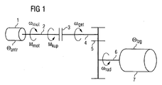
- Fig. 1 shows therefore a schematic representation of a vehicle drive train, in which a drive torque M mot is generated by an internal combustion engine 1 at an engine speed ⁇ mot , which is transmitted via the crankshaft 2 to the input side of a starting and shifting clutch 3.
- this clutch 3 forwards this torque as clutch torque M kup via a transmission input shaft 4 at a speed ⁇ get to gear ratios of a transmission 5, which in this simplified representation comprises an automated transmission with differential gear.
- the drive torque to axle drive shafts 6 of the vehicle 7 is passed on, which ultimately drive the vehicle wheels, not shown here with a wheel speed ⁇ rad .
- ⁇ antr represents the sum of all drive inertia moments and ⁇ fzg the sum of all remaining vehicle inertia torques .
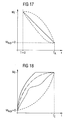
- the Kupplungsistmoment for the respective switching operation in the form of a straight line, a freely adjustable course from a map or with PT1 or. controlled with PT2 characteristic to the target value calculated from the driver's desired torque (see also FIGS. 17 and 18 ).
- the period until reaching the target speed or the synchronous speed is preferably estimated from the current gradient of the engine speed ⁇ mot and the transmission input speed ⁇ get . If this period is a calibrated and from the driver's desired torque M soll and the engagement speed dependent threshold value falls below, the engine speed ⁇ mot is alleged by a defined in a map speed curve to the transmission input speed ⁇ get . In this map, the target speed difference over the elapsed time t is preferably entered.
- the vehicle acceleration a fzg which represents the target variable of the engagement process, is normally proportional to the wheel acceleration ⁇ rad and thus taking into account the Overall ratio of manual transmission and differential gear also proportional to the acceleration of the transmission input shaft ⁇ get : a veh ⁇ ⁇ • wheel ⁇ ⁇ • get
- M kup ⁇ ⁇ * veh ⁇ ⁇ • get .
- ⁇ * fzg referred to the transmission input side moment of inertia ⁇ fzg all rotating components of the drive train from the clutch 3 to the vehicle wheels including the converted into an equivalent moment of inertia vehicle mass.
- M ⁇ ⁇ * veh + ⁇ antr ⁇ • get .
- ⁇ antr is the sum of all the drive-side moment of inertia and M is the driver's desired torque , which is provided by the drive motor 1.
- the clutch torque should not be controlled exactly to the driver's desired torque M soll , but only up to the following value, which is always slightly below the driver's desired torque M soll :
- M kup M should ⁇ ⁇ * veh ⁇ * veh + ⁇ antr
- This correction is particularly important at low gears associated with a then very large gear ratio ü important because then the transformed to the transmission input side moment of inertia ⁇ * fzg is particularly small in relation to the drive-side moment of inertia ⁇ antr . In high gears, this correction is increasingly less noticeable, since then the drive-side moment of inertia ⁇ antr is very small in relation to the output side moment of inertia ⁇ * fzg .
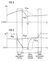
- Fig. 2 on the basis of a flow chart for a control and regulation program to be stored in a vehicle computer, as well as FIG. 3 and FIG. 4
- transmission input speed ⁇ mot With respect to the time course of engine speed ⁇ mot , transmission input speed ⁇ get , engine torque M mot and clutch torque M kup can be removed in a train upshift, according to the invention in a transmission shift operation first an engine torque control, then an engine speed control and finally an engine torque control again performed.
- the engine torque control is performed before and during the first phase of the gear change by an engine control unit.
- a transmission control device checks in close time intervals whether there is a gear change request signaled by the behavior of the driver.
- This gear change request can be generated by sensors on a transmission shifting device and / or by the transmission control device itself, if it automatically comes to the conclusion on the basis of other sensor information that the driver desires an automatically triggered gear shift.
- a gear change request has been determined, is in accordance with the schedule in Fig. 2 in a second method step 20 reduces the clutch and the engine torque M kup , M mot .
- This control flow is in FIG. 3 and FIG. 4 graphically labeled as the area where motor torque routing occurs during the shift.
- M mot is constantly checked, for example, by the transmission control unit in a method step 30, whether clutch slip occurs or the clutch is fully open. If there is no clutch slip or if the clutch is not yet fully open, the engine torque M mot and the clutch torque M kup is further reduced.
- the transmission control device detects clutch slippage or an opened clutch, in a next method step 40 the engine speed curve is preferably calculated according to the above-described mathematical contexts.
- a clutch torque control and an engine speed control are carried out in such a way that according to FIG Fig. 3 the engine speed is reduced with the calculated course regulated to a target engine speed.
- This target speed corresponds to the transmission input speed ⁇ get taking into account the transmission ratio of the target gear and the vehicle wheel speed ⁇ rad at the current vehicle speed or comes this at least close.
- the engine speed control for example, the transmission control unit continuously checks in a step 60 whether the target gear is engaged and if the engine speed ⁇ mot in the above-mentioned target range is. If both the target gear in the transmission 5 is mechanically engaged and the engine speed ⁇ mot in the predetermined target speed range is from a time t ZG in a step 70 by gradually closing the clutch 3 as long as an increase of the clutch torque M kup made until the desired torque M should be reached by the driver ( Fig. 4 ).
- the engine control unit ⁇ mot, soll is again determined anew and a directed to the achievement of the target engine speed engine speed control is preferably performed by the transmission control unit with slowly rising clutch torque M kup in a step 80. In this case, it is checked in a method step 90 whether clutch slip still occurs or whether the clutch is still open.
- step 30 If, as at the beginning of the shift process (step 30) clutch slippage still takes place or the clutch 3 is still fully open, this is interpreted as indicating that the clutch 3 still no or at least no significant torque M kup forwarded to the transmission. Therefore, according to Fig. 2 branched back to the method step 70 and continued with the increase of the clutch torque M kup by closing the clutch 3 under constant engine speed calculation and engine speed control.
- step 90 Was found except as indicated in step 90 that no clutch slip occurs or the clutch is not opened, then the clutch 3 is completely closed at a step 100 and the clutch torque M kup and the engine torque M mot raised until the desired torque M soll of Driver is reached.
- the switching process is considered completed and transitioned from the engine speed control to an engine torque control, the latter preferably being performed again by the engine control unit.
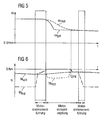
- gear reduction in the train operation of the vehicle is the engine speed ⁇ mot to raise while the transmission input speed ⁇ get increases by the operation of the synchronization device.
- the motor torque M mot is controlled down at the beginning of the shifting process parallel to the opening of the clutch 3.
- the determination of the slippage of the clutch 3 is changed from the engine torque control to the engine speed control, so that even before the clutch 3 transmits no more torque, the engine speed ⁇ mot is raised until reaching the target engine speed (synchronous speed).
- This is accompanied by an increase in the engine torque M mot , which, however, drops to zero with the return of the "intermediate gas".
- the clutch 3 is then closed on command of example, the transmission control unit steadily and the engine torque M mot raised until this engine torque M mot has reached the desired torque M soll the driver. This is followed by a change from the engine speed control to the engine torque control, which then preferably again carries out the engine control unit. As a result, the clutch torque M kup may continue to increase, while the engine torque M mot corresponds to the desired torque M soll signaled by the deflection of the accelerator pedal.
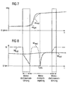
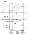
- FIG. 9 shows Fig. 9 the time course of the engine speed ⁇ mot and the transmission input shaft speed ⁇ get and Fig. 10 the course of the desired torque M should the driver, the clutch torque M kup and the engine torque M mot during a downshift in overrun operation without engine torque increase.
- Fig. 10 can be removed, is applied to the clutch 3 before the shift a negative clutch torque M kup , which is reduced at the beginning of the switching operation with the opening of the clutch 3 to a value of zero.
- the engine speed ⁇ mot increases because, as a result of the closing of the clutch 3, the engine 1 is driven via the transmission 5. Mot the engine torque M falls gradually until the desired negative torque M soll from which is approximately attained when the engine speed ⁇ MOT of the target speed of the transmission input shaft ⁇ corresponds to get.
- the command is issued by the transmission control unit to fully close the clutch 3 and from the engine speed control to the engine torque control switched over, as a result of which the clutch torque M kup drops to the value before the start of the shift.
- the engine speed control is based on calculated engine speed command values. These setpoint specifications may depend on which switching speed is desired. Thus, in the same vehicle depending on the particular driving situations or depending on different drivers sporty fast or comfortable and slightly slower switching operations may be desired.
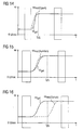
- Fig. 11 shows by way of example the course of the transmission input speed ⁇ get and the engine target speed ⁇ mot in a sporty upshift while Fig. 12 these courses in a comfortable upshift and Fig. 13 represents at a push downshift.
- Fig. 12 these courses in a comfortable upshift
- Fig. 13 represents at a push downshift.
- different setpoint curves of the engine speed ⁇ mot have been calculated for these switching operations, which lead to different long switching periods.
- FIGS. 14, 15 and 16 different setpoint curves of the engine speed ⁇ mot shown during various downshifts. So shows Fig. 14 the course of the engine target speed ⁇ mot during a train-downshift with a sporty character, while Fig. 15 a train-downshift with comfort character is removable. Finally, in Fig. 16 a comfort-boost downshift shown, the engine target speed curve leads to a slightly longer switching time.
- Fig. 18 shows finally different gradients of Kupplungsistmomentes from a time T A with the clutch 3 open until a time T E , in which the clutch 3 is closed again and the desired torque M is the driver transmitted through the clutch 3. From this representation it is clear that the control of the clutch torque during the switching operation can be made arbitrary by appropriate specifications.
Landscapes
- Engineering & Computer Science (AREA)
- Mechanical Engineering (AREA)
- Chemical & Material Sciences (AREA)
- Combustion & Propulsion (AREA)
- General Engineering & Computer Science (AREA)
- Transportation (AREA)
- Automation & Control Theory (AREA)
- Control Of Transmission Device (AREA)
- Control Of Driving Devices And Active Controlling Of Vehicle (AREA)
- Control Of Vehicle Engines Or Engines For Specific Uses (AREA)
- Hydraulic Clutches, Magnetic Clutches, Fluid Clutches, And Fluid Joints (AREA)
Claims (19)
- Procédé de commande et de réglage du couple moteur et du couple d'embrayage durant une opération de commutation d'une transmission de vitesse automatique ou d'une transmission de vitesse à double embrayage, comprenant les étapes suivantes :a) commander le couple moteur ;b) déterminer la nécessité d'un changement de rapport ;c) réduire le couple d'embrayage et le couple moteur ;d) arrêter la commande du couple moteur dès qu'un glissement de l'embrayage se produit ou que l'embrayage est complètement ouvert ;e) régler le régime du moteur sur un écart prédéfini par rapport au régime d'entrée de la transmission (régime synchrone) du rapport cible ;f) déterminer que le rapport cible est engagé et que le régime du moteur se situe dans la plage cible (régime synchrone) ;g) augmenter le couple d'embrayage ; eth) arrêter la régulation du régime du moteur et commander le couple moteur dès que le couple d'embrayage (Mkup) a atteint une valeur finale afférente pour cette opération de commutation,i) dans lequel la commande du couple d'embrayage a lieu pendant toute la durée de l'opération de commutation, et le régime cible du moteur est calculé à partir des régimes des roues du véhicule (ωrad), du rapport de transmission différentiel et du rapport de transmission.
- Procédé selon la revendication 1, caractérisé en ce que, pendant le réglage du régime du moteur, on utilise une courbe prédéfinie du couple d'embrayage (Mkup) pour déterminer le régime théorique du moteur (ωmot, soll, neu) et le couple moteur (Mmot) précommandé.
- Procédé selon la revendication 1 ou la revendication 2, caractérisé en ce que la commande et/ou le réglage du couple moteur (Mmot) est réalisée avant le début de l'opération de commutation et après la fin de l'opération de commutation par un appareil de commande du moteur.
- Procédé selon l'une au moins des revendications précédentes, caractérisé en ce que le réglage du régime du moteur a lieu pendant l'opération de commutation dans un appareil de commande de la transmission.
- Procédé selon la revendication 3, caractérisé en ce que le réglage du régime du moteur a lieu pendant l'opération de commutation par l'appareil de commande du moteur.
- Procédé selon la revendication 4 ou la revendication 5, caractérisé en ce que l'appareil de commande de la transmission transmet le régime théorique du moteur (ωmot) et/ou le couple d'embrayage (Mkup) réel à l'appareil de commande du moteur.
- Procédé selon l'une au moins des revendications précédentes, caractérisé en ce que le régime du moteur (ωmot) se situe dans la plage cible à partir du moment où à un couple demandé (Msoll) par le conducteur et positif, le régime du moteur (ωmot) est supérieur ou égal au régime d'entrée de la transmission (ωget), ou à partir du moment où à un couple demandé (Msoll) par le conducteur et négatif, le régime du moteur (ωmot) est inférieur ou égal au régime d'entrée de la transmission (ωget).
- Procédé selon l'une au moins des revendications précédentes, caractérisé en ce que l'on passe du réglage du régime du moteur à la commande du couple moteur à partir du moment où dans une phase de réembrayage, la différence de régime entre le régime du moteur (ωmot) et le régime d'entrée de la transmission (ωget) est ajustée en fonction l'un de l'autre, et le couple d'embrayage (Mkup) est ajusté de manière sûre au couple demandé (Msoll) par le conducteur.
- Procédé selon l'une au moins des revendications précédentes, caractérisé en ce que le régime cible du moteur (régime synchrone) est déterminé à partir du régime d'entrée mesuré de la transmission (ωget).
- Procédé selon l'une au moins des revendications précédentes, caractérisé en ce que le couple d'embrayage réel est commandé sous la forme d'une courbe linéaire, d'une courbe librement ajustable à partir d'un champ de caractéristiques mémorisé ou à l'aide d'une caractéristique PT1 ou PT2, vers la valeur cible calculée à partir du couple demandé (Msoll) par le conducteur.
- Procédé selon l'une au moins des revendications précédentes, caractérisé en ce que, à partir des gradients actuels de régime du moteur et de régime d'entrée de la transmission (ωmot, ωget), on estime le moment où lesdits deux régimes (ωmot, ωget) seront probablement à nouveau synchrones.
- Procédé selon la revendication 11, caractérisé en ce que le régime du moteur (ωmot) est ajusté au régime d'entrée de la transmission (ωget), selon une courbe de régime définie dans un champ de caractéristiques, lorsque la durée estimée jusqu'à ce que le régime synchrone soit atteint est inférieure à une valeur seuil prédéfinie dépendante du couple demandé (Msoll) par le conducteur et de la vitesse d'embrayage.
- Procédé selon la revendication 12, caractérisé en ce que dans le champ de caractéristiques, la différence de régime théorique lors d'une opération de commutation est mémorisée pendant tout le temps écoulé durant une opération de commutation.
- Procédé selon l'une au moins des revendications précédentes, caractérisé en ce que le régime théorique du moteur (ωmot, soll, neu) pour une opération de commutation est calculé comme suit :

où ωmot, soll, alt est le régime théorique du moteur jusqu'à présent, Δt est un intervalle de temps, Θ antr est la somme de tous les moments d'inertie de l'entraînement, M'mot est le couple résistant du moteur et Mkup est le couple d'embrayage théorique. - Procédé selon la revendication 13, caractérisé en ce que, lors du réembrayage pendant la phase de glissement, le couple d'embrayage (Mkup) théorique est amené non pas exactement jusqu'au couple demandé (Msoll) par le conducteur mais seulement jusqu'à une valeur qui est légèrement inférieure au couple demandé (Msoll) par le conducteur et qui est donnée par l'équation

où Θ antr est la somme de tous les moments d'inertie côté entraînement et Θ* fzg est le moment d'inertie afférent au côté entrée de la transmission, de tous les composants rotatifs de la chaîne cinématique, y compris la masse du véhicule convertie en moment d'inertie équivalent. - Procédé selon l'une au moins des revendications précédentes, caractérisé en ce que, lors d'une rétrogradation avec demande d'accélération, le couple d'embrayage (Mkup) est augmenté seulement à partir du moment où le régime du moteur (ωmot) est supérieur ou égal au régime de transmission (ωget) du rapport cible.
- Procédé selon l'une au moins des revendications précédentes, caractérisé en ce que, lors d'une rétrogradation avec demande de décélération, le régulateur de régime du moteur n'augmente pas le régime du moteur.
- Procédé selon l'une au moins des revendications précédentes, caractérisé en ce que, lors d'une rétrogradation avec demande de décélération, le régime du moteur est augmenté lentement de manière adaptée à partir du moment où une très faible décélération du véhicule génèrerait une durée d'embrayage intolérablement longue.
- Procédé selon l'une au moins des revendications précédentes, caractérisée en ce qu'il comprend les étapes de procédé suivantes :a) contrôler la nécessité d'un changement de rapport (étape 10) ;b) si un changement de rapport est nécessaire, réduire le couple d'embrayage et le couple moteur (étape 20) ;c) contrôler si un glissement de l'embrayage se produit ou si l'embrayage est complètement ouvert (étape 30) ;d) en l'absence de glissement de l'embrayage ou si l'embrayage n'est pas encore complètement ouvert, revenir au point b (= étape 20) ;e) si un glissement de l'embrayage se produit ou si l'embrayage est complètement ouvert, calculer la courbe de régime du moteur (étape 40) ;f) effectuer la commande du couple d'embrayage et le réglage du régime du moteur (étape 50) ;g) contrôler si le rapport cible est engagé et si le régime du moteur se situe dans la plage cible (étape 60) ;h) si le rapport cible n'est pas encore engagé et si le régime cible du moteur n'a pas encore été atteint, revenir au point e (= étape 40) ;i) si le rapport cible est engagé et le régime cible du moteur atteinte, augmenter le couple d'embrayage (étape 70) ;j) calculer le régime théorique du moteur et effectuer un réglage du régime du moteur (étape 80) ;k) contrôler si un glissement de l'embrayage se produit ou si l'embrayage est ouvert (étape 90) ;l) si un glissement de l'embrayage se produit ou si l'embrayage est encore ouvert, revenir au point i (= étape 70) ;m) en l'absence de glissement de l'embrayage et si l'embrayage n'est plus ouvert, augmenter le couple d'embrayage et le couple moteur (étape 100) ;n) vérifier que l'embrayage est fermé et que le couple demandé par le conducteur a été atteint (étape 110).
Applications Claiming Priority (2)
| Application Number | Priority Date | Filing Date | Title |
|---|---|---|---|
| DE10301502 | 2003-01-16 | ||
| DE10301502 | 2003-01-16 |
Publications (3)
| Publication Number | Publication Date |
|---|---|
| EP1439087A2 EP1439087A2 (fr) | 2004-07-21 |
| EP1439087A3 EP1439087A3 (fr) | 2008-07-09 |
| EP1439087B1 true EP1439087B1 (fr) | 2013-05-08 |
Family
ID=32520005
Family Applications (1)
| Application Number | Title | Priority Date | Filing Date |
|---|---|---|---|
| EP03029036.5A Expired - Lifetime EP1439087B1 (fr) | 2003-01-16 | 2003-12-16 | Procédé de commande et de régulation du couple moteur et du couple d'embrayage durant un changement de vitesse d'une transmission robotisée ou à double embrayage |
Country Status (1)
| Country | Link |
|---|---|
| EP (1) | EP1439087B1 (fr) |
Cited By (1)
| Publication number | Priority date | Publication date | Assignee | Title |
|---|---|---|---|---|
| DE102016211735A1 (de) | 2016-06-29 | 2018-01-04 | Volkswagen Aktiengesellschaft | Verfahren zur Steuerung und/oder zur Regelung eines Antriebsstrangs eines Kraftfahrzeugs mit einem Antriebsmotor und mit mindestens einer Kupplung |
Families Citing this family (43)
| Publication number | Priority date | Publication date | Assignee | Title |
|---|---|---|---|---|
| DE102004019215A1 (de) * | 2004-04-21 | 2005-11-24 | Zf Friedrichshafen Ag | Verfahren zur Einstellung der Schaltdauer eines Automatgetriebes |
| DE102004046066A1 (de) * | 2004-09-23 | 2006-04-13 | Daimlerchrysler Ag | Einrichtung und Verfahren zur Durchführung einer Rückschaltung in einem lastschaltbaren Getriebe |
| GB0609333D0 (en) | 2006-05-11 | 2006-06-21 | Zeroshift Ltd | Engagement member actuator control |
| GB0510129D0 (en) | 2005-05-18 | 2005-06-22 | Zeroshift Ltd | Sequential hub layout |
| DE102005049178A1 (de) * | 2005-10-14 | 2007-04-19 | Zf Friedrichshafen Ag | Verfahren und Vorrichtung zur Steuerung eines Gangwechsels eines automatisierten Schaltgetriebes |
| DE102006003711A1 (de) * | 2006-01-26 | 2007-08-02 | Zf Friedrichshafen Ag | Verfahren zur Steuerung eines Kraftfahrzeug-Antriebsstrangs |
| FR2896750B1 (fr) * | 2006-01-30 | 2009-11-13 | Peugeot Citroen Automobiles Sa | Procede de commande d'un groupe motopropulseur de vehicule automobile |
| EP2196706B1 (fr) * | 2006-08-09 | 2011-12-07 | Schaeffler Technologies AG & Co. KG | Dispositif et procédé de commande d'une transmission à double embrayages |
| DE102008014683B4 (de) * | 2008-03-18 | 2010-04-08 | Continental Automotive Gmbh | Verfahren und Steuereinheit zum Betreiben eines Hybridantriebs |
| DE102008026509B4 (de) * | 2008-05-21 | 2013-08-01 | Getrag Getriebe- Und Zahnradfabrik Hermann Hagenmeyer Gmbh & Cie Kg | Verfahren und Vorrichtung zur Verwendung in einer Steuerung eines Antriebsstrangs eines Kraftfahrzeuges |
| DE102008046851B4 (de) | 2008-09-08 | 2022-01-13 | Dr. Ing. H.C. F. Porsche Aktiengesellschaft | Verfahren zur Steuerung eines Triebstrangs eines Kraftfahrzeugs |
| DE102008043980A1 (de) * | 2008-11-21 | 2010-05-27 | Robert Bosch Gmbh | Verfahren zur Drehzahlregelung |
| RU2496668C2 (ru) * | 2008-12-19 | 2013-10-27 | Вольво Ластвагнар Аб | Способ и устройство управления выключением автоматического главного сцепления транспортного средства |
| DE102009015165B4 (de) * | 2009-03-26 | 2016-11-17 | Bayerische Motoren Werke Aktiengesellschaft | Verfahren zur Steuerung des Gangwechsels in einem Kraftfahrzeug |
| DE102009032745A1 (de) * | 2009-07-11 | 2011-01-13 | Dr. Ing. H.C. F. Porsche Aktiengesellschaft | Verfahren zur Anpassung eines Antriebsmoments |
| US8504261B2 (en) * | 2010-03-17 | 2013-08-06 | GM Global Technology Operations LLC | Powertrain control systems and methods with parameter transfer between an ECM and a TCM for ECM and TCM based control |
| GB201109100D0 (en) | 2011-05-27 | 2011-07-13 | Zeroshift Ltd | Transmission system |
| WO2012171521A1 (fr) * | 2011-06-16 | 2012-12-20 | Schaeffler Technologies AG & Co. KG | Procédé de commande d'un embrayage à friction automatique dans une chaîne cinématique d'un véhicule automobile pendant une procédure de démarrage |
| JP5873665B2 (ja) * | 2011-08-30 | 2016-03-01 | アイシン・エーアイ株式会社 | 車両用デュアルクラッチ式変速機 |
| JP5822615B2 (ja) | 2011-09-20 | 2015-11-24 | アイシン・エーアイ株式会社 | 自動クラッチ制御装置およびその変速制御方法 |
| FR2985708B1 (fr) * | 2012-01-12 | 2014-03-21 | Renault Sa | Procede de gestion d'une boite robotisee pendant un changement de rapport montant sous charge, et dispositif correspondant |
| JP5849930B2 (ja) * | 2012-10-25 | 2016-02-03 | アイシン精機株式会社 | 車両用駆動装置 |
| DE102013204411B4 (de) | 2013-03-14 | 2026-08-20 | Zf Friedrichshafen Ag | Verfahren zur Durchführung von Schubrückschaltungen mit Beteiligung eines formschlüssigen Schaltelementes bei einem Automatgetriebe umfassend eine Wandlerüberbrückungskupplung |
| JP6036473B2 (ja) * | 2013-03-27 | 2016-11-30 | アイシン精機株式会社 | 車両用駆動装置 |
| DE102013216144A1 (de) * | 2013-08-14 | 2015-02-19 | Zf Friedrichshafen Ag | Verfahren zur Schaltsteuerung eines Fahrzeuggetriebes |
| DE102013112969A1 (de) | 2013-11-25 | 2015-05-28 | Dr. Ing. H.C. F. Porsche Aktiengesellschaft | Verfahren zum Steuern eines Verbrennungsmotors |
| FR3055283B1 (fr) * | 2016-08-23 | 2018-08-31 | Peugeot Citroen Automobiles Sa | Procede de controle d'un couple moteur d'un vehicule, notamment automobile |
| DE102016221698B4 (de) | 2016-11-04 | 2018-05-30 | Audi Ag | Verfahren zum Betreiben eines Mehrkupplungsgetriebes, Mehrkupplungsgetriebe für ein Kraftfahrzeug und Kraftfahrzeug mit einem Mehrkupplungsgetriebe |
| DE102017203108A1 (de) | 2017-02-27 | 2018-08-30 | Volkswagen Aktiengesellschaft | Verfahren zur Steuerung eines Automatikgetriebes |
| DE102018200774A1 (de) * | 2018-01-18 | 2019-07-18 | Zf Friedrichshafen Ag | Getriebesteuerung |
| DE102018221852A1 (de) * | 2018-12-17 | 2020-06-18 | Zf Friedrichshafen Ag | Verfahren zum Durchführen eines Gangwechsels, Steuerungseinrichtung sowie Kraftfahrzeug |
| CN111361569B (zh) * | 2020-02-19 | 2022-08-26 | 重庆大学 | 一种基于模型的湿式dct离合器转矩实时估计方法 |
| CN112622865B (zh) * | 2020-12-24 | 2022-04-26 | 潍柴动力股份有限公司 | 汽车的挂挡控制方法、装置、电子设备以及存储介质 |
| CN114909467B (zh) * | 2021-02-07 | 2024-04-12 | 广汽埃安新能源汽车有限公司 | 一种车辆升挡控制方法、装置及存储介质 |
| CN113503359B (zh) * | 2021-07-22 | 2023-01-06 | 重庆长安汽车股份有限公司 | Phev车型的双离合自动变速器的离合器扭矩控制方法及系统 |
| CN114542707A (zh) * | 2022-02-28 | 2022-05-27 | 海马汽车有限公司 | 一种换挡控制方法、装置及车辆 |
| CN114922972B (zh) * | 2022-05-18 | 2024-03-26 | 中国第一汽车股份有限公司 | 双离合器自动变速器升挡的自适应控制方法及自动变速器 |
| CN114802195B (zh) * | 2022-05-25 | 2025-02-21 | 中国第一汽车股份有限公司 | 车辆的换挡方法及装置 |
| CN115095654B (zh) * | 2022-06-28 | 2023-09-19 | 东风汽车集团股份有限公司 | 一种双离合自动变速器动力降挡发动机转速同步控制方法 |
| DE102023200541B4 (de) * | 2023-01-24 | 2025-11-13 | Audi Aktiengesellschaft | Verfahren zum Betreiben einer Antriebseinrichtung für ein Kraftfahrzeug sowie entsprechende Antriebseinrichtung |
| CN116292874B (zh) * | 2023-02-28 | 2026-05-15 | 重庆青山工业有限责任公司 | 一种平稳的dct滑行降挡控制方法 |
| CN117072673A (zh) * | 2023-09-01 | 2023-11-17 | 北京福田戴姆勒汽车有限公司 | 换挡控制方法、换挡控制系统和车辆 |
| CN119641896B (zh) * | 2024-12-06 | 2026-03-24 | 极光湾(宁波)智能科技有限公司 | 换挡控制方法、装置及车辆 |
Family Cites Families (7)
| Publication number | Priority date | Publication date | Assignee | Title |
|---|---|---|---|---|
| IT1266914B1 (it) * | 1994-08-05 | 1997-01-21 | Magneti Marelli Spa | Sistema di controllo di un cambio servoassistito. |
| US5583766A (en) * | 1994-12-07 | 1996-12-10 | Caterpillar Inc. | Integrated engine and transmission control system |
| IT1286104B1 (it) * | 1996-06-17 | 1998-07-07 | Fiat Ricerche | Sistema di controllo per un cambio servocomandato di un autoveicolo, e relativo procedimento |
| JP2000205399A (ja) * | 1998-12-31 | 2000-07-25 | Dana Corp | 多速度車軸シフティング装置の制御方法 |
| DE19904129C1 (de) * | 1999-02-03 | 2000-02-24 | Mannesmann Sachs Ag | Verfahren zur Durchführung von Schaltvorgängen bei einem Antriebssystem |
| DE19943334A1 (de) * | 1999-09-10 | 2001-06-07 | Zahnradfabrik Friedrichshafen | Verfahren zur Regelung einer Kupplung oder einer Bremse in einem Getriebe |
| DE60121484T2 (de) * | 2000-07-17 | 2007-09-27 | Hitachi, Ltd. | Steuerungsverfahren und Steuerungssystem für ein Kraftfahrzeug |
-
2003
- 2003-12-16 EP EP03029036.5A patent/EP1439087B1/fr not_active Expired - Lifetime
Cited By (2)
| Publication number | Priority date | Publication date | Assignee | Title |
|---|---|---|---|---|
| DE102016211735A1 (de) | 2016-06-29 | 2018-01-04 | Volkswagen Aktiengesellschaft | Verfahren zur Steuerung und/oder zur Regelung eines Antriebsstrangs eines Kraftfahrzeugs mit einem Antriebsmotor und mit mindestens einer Kupplung |
| DE102016211735B4 (de) | 2016-06-29 | 2022-01-27 | Volkswagen Aktiengesellschaft | Verfahren und Steuergerät zur Steuerung und/oder zur Regelung eines Antriebsstrangs eines Kraftfahrzeugs mit einem Antriebsmotor und mit mindestens einer Kupplung |
Also Published As
| Publication number | Publication date |
|---|---|
| EP1439087A2 (fr) | 2004-07-21 |
| EP1439087A3 (fr) | 2008-07-09 |
Similar Documents
| Publication | Publication Date | Title |
|---|---|---|
| EP1439087A2 (fr) | Procédé de commande et de régulation du couple moteur et du couple d'embrayage durant un changement de vitesse d'une transmission robotisée ou à double embrayage | |
| EP0580827B1 (fr) | Dispositif de reglage du couple de sortie d'une boite de vitesses automatique | |
| EP0670789B1 (fr) | Procede permettant de moduler le couple de sortie d'une boite de vitesses automatique | |
| DE102006005468B4 (de) | Verfahren zum Betreiben eines Parallelhybridantriebsstranges eines Fahrzeuges | |
| DE69524165T2 (de) | Wiedereinkupplungssteuerung | |
| EP2619481B1 (fr) | Procédé d'adaptation de la courbe caractéristique d'embrayages dans une demi-boîte de vitesses à double embrayage d'un véhicule | |
| EP2094552B1 (fr) | Procédé de réalisation d'un changement de vitesse d'une boîte de vitesses automatique | |
| DE102005012864B4 (de) | Verfahren zum Steuern von Getriebeschaltpunkten für ein Hybridfahrzeug mit primärer und sekundärer Antriebsquelle | |
| EP2619482B1 (fr) | Procédé de commande de changements de vitesse d'une boîte de vitesses de véhicule | |
| EP2083198A2 (fr) | Procédé et appareil de commande destinés à la commande d'un faisceau d'entraînement, comprenant une boîte de vitesse double | |
| DE4321413C2 (de) | Verfahren und Vorrichtung zur Steuerung der Antriebsleistung eines Fahrzeugs | |
| EP2619479B1 (fr) | Procédé de commande des passages de rapport d'une boîte de vitesses automatisée | |
| EP1564446B1 (fr) | Méthode et dispostif de commande de changement de vitesse pour transmission véhiculaire à changement parallèle | |
| EP2240709B1 (fr) | Dispositif et procede empechant le passage de rapports inadequats dans des transmissions automatiques de vehicules motorises | |
| DE4446120A1 (de) | Verfahren und Anordnung zum adaptiven Abschalten der Abgasbremse bei Schaltvorgängen | |
| DE102013021441A1 (de) | Verfahren zum Betrieb eines Fahrzeugs | |
| EP1181166B1 (fr) | Procede permettant de commander un ensemble d'entrainement d'un systeme d'entrainement sur la base d'un deroulement predictif pour une certaine grandeur de fonctionnement | |
| DE102016120396A1 (de) | Schaltsteuersystem für ein Automatikgetriebe | |
| EP0651182A2 (fr) | Procédé de commande d'une variable de réglage, déterminant la différence de vitesse de rotation d'un embrayage d'automobile | |
| EP1382479B1 (fr) | Méthode de démarrage d'un système de transmission de véhicule avec une boîte de vitesse à double embrayage | |
| DE102011008597A1 (de) | Verfahren und Mittel zum Steuern des Herunterschaltens | |
| DE10308713B4 (de) | Doppelkupplungsgetriebe und Verfahren zum Steuern und/oder Regeln eines Doppelkupplungsgetriebes bei einer Überschneidungsschaltung | |
| DE602005003018T2 (de) | Steuerung und Steuerungsmethode für das Anfahrmanöver eines Kraftfahrzeugs mit automatisiertem Getriebe | |
| DE19922694A1 (de) | Verfahren zur Steuerung eines Automatgetriebes eines Kraftfahrzeuges | |
| DE10290843B4 (de) | Verfahren zum Steuern und/oder Regeln eines automatisierten Getriebes eines Fahrzeuges mit dem ein Einkuppelvorgang bei einem Gangwechsel durchgeführt wird |
Legal Events
| Date | Code | Title | Description |
|---|---|---|---|
| PUAI | Public reference made under article 153(3) epc to a published international application that has entered the european phase |
Free format text: ORIGINAL CODE: 0009012 |
|
| AK | Designated contracting states |
Kind code of ref document: A2 Designated state(s): AT BE BG CH CY CZ DE DK EE ES FI FR GB GR HU IE IT LI LU MC NL PT RO SE SI SK TR |
|
| AX | Request for extension of the european patent |
Extension state: AL LT LV MK |
|
| RAP1 | Party data changed (applicant data changed or rights of an application transferred) |
Owner name: CONTINENTAL AUTOMOTIVE GMBH |
|
| PUAL | Search report despatched |
Free format text: ORIGINAL CODE: 0009013 |
|
| AK | Designated contracting states |
Kind code of ref document: A3 Designated state(s): AT BE BG CH CY CZ DE DK EE ES FI FR GB GR HU IE IT LI LU MC NL PT RO SE SI SK TR |
|
| AX | Request for extension of the european patent |
Extension state: AL LT LV MK |
|
| 17P | Request for examination filed |
Effective date: 20090109 |
|
| AKX | Designation fees paid |
Designated state(s): DE FR IT |
|
| 17Q | First examination report despatched |
Effective date: 20110228 |
|
| REG | Reference to a national code |
Ref country code: DE Ref legal event code: R079 Ref document number: 50314787 Country of ref document: DE Free format text: PREVIOUS MAIN CLASS: B60K0041020000 Ipc: B60W0010060000 |
|
| GRAP | Despatch of communication of intention to grant a patent |
Free format text: ORIGINAL CODE: EPIDOSNIGR1 |
|
| RIC1 | Information provided on ipc code assigned before grant |
Ipc: B60W 10/06 20060101AFI20121211BHEP Ipc: F16H 61/688 20060101ALI20121211BHEP |
|
| GRAS | Grant fee paid |
Free format text: ORIGINAL CODE: EPIDOSNIGR3 |
|
| GRAA | (expected) grant |
Free format text: ORIGINAL CODE: 0009210 |
|
| AK | Designated contracting states |
Kind code of ref document: B1 Designated state(s): DE FR IT |
|
| REG | Reference to a national code |
Ref country code: DE Ref legal event code: R096 Ref document number: 50314787 Country of ref document: DE Effective date: 20130704 |
|
| PG25 | Lapsed in a contracting state [announced via postgrant information from national office to epo] |
Ref country code: IT Free format text: LAPSE BECAUSE OF FAILURE TO SUBMIT A TRANSLATION OF THE DESCRIPTION OR TO PAY THE FEE WITHIN THE PRESCRIBED TIME-LIMIT Effective date: 20130508 |
|
| PLBE | No opposition filed within time limit |
Free format text: ORIGINAL CODE: 0009261 |
|
| STAA | Information on the status of an ep patent application or granted ep patent |
Free format text: STATUS: NO OPPOSITION FILED WITHIN TIME LIMIT |
|
| 26N | No opposition filed |
Effective date: 20140211 |
|
| REG | Reference to a national code |
Ref country code: DE Ref legal event code: R097 Ref document number: 50314787 Country of ref document: DE Effective date: 20140211 |
|
| REG | Reference to a national code |
Ref country code: FR Ref legal event code: ST Effective date: 20140829 |
|
| PG25 | Lapsed in a contracting state [announced via postgrant information from national office to epo] |
Ref country code: FR Free format text: LAPSE BECAUSE OF NON-PAYMENT OF DUE FEES Effective date: 20131231 |
|
| PGFP | Annual fee paid to national office [announced via postgrant information from national office to epo] |
Ref country code: DE Payment date: 20181231 Year of fee payment: 16 |
|
| REG | Reference to a national code |
Ref country code: DE Ref legal event code: R081 Ref document number: 50314787 Country of ref document: DE Owner name: VITESCO TECHNOLOGIES GMBH, DE Free format text: FORMER OWNER: CONTINENTAL AUTOMOTIVE GMBH, 30165 HANNOVER, DE |
|
| REG | Reference to a national code |
Ref country code: DE Ref legal event code: R119 Ref document number: 50314787 Country of ref document: DE |
|
| PG25 | Lapsed in a contracting state [announced via postgrant information from national office to epo] |
Ref country code: DE Free format text: LAPSE BECAUSE OF NON-PAYMENT OF DUE FEES Effective date: 20200701 |