EP2083208B1 - Appareil, destiné à fixer un objet à un mur, ainsi qu'un élément mural et un élément de soutien qui sont adaptés à un tel appareil - Google Patents
Appareil, destiné à fixer un objet à un mur, ainsi qu'un élément mural et un élément de soutien qui sont adaptés à un tel appareil Download PDFInfo
- Publication number
- EP2083208B1 EP2083208B1 EP09000907A EP09000907A EP2083208B1 EP 2083208 B1 EP2083208 B1 EP 2083208B1 EP 09000907 A EP09000907 A EP 09000907A EP 09000907 A EP09000907 A EP 09000907A EP 2083208 B1 EP2083208 B1 EP 2083208B1
- Authority
- EP
- European Patent Office
- Prior art keywords
- hook
- wall
- slider
- support member
- support
- Prior art date
- Legal status (The legal status is an assumption and is not a legal conclusion. Google has not performed a legal analysis and makes no representation as to the accuracy of the status listed.)
- Active
Links
Images

Classifications
-
- F—MECHANICAL ENGINEERING; LIGHTING; HEATING; WEAPONS; BLASTING
- F16—ENGINEERING ELEMENTS AND UNITS; GENERAL MEASURES FOR PRODUCING AND MAINTAINING EFFECTIVE FUNCTIONING OF MACHINES OR INSTALLATIONS; THERMAL INSULATION IN GENERAL
- F16M—FRAMES, CASINGS OR BEDS OF ENGINES, MACHINES OR APPARATUS, NOT SPECIFIC TO ENGINES, MACHINES OR APPARATUS PROVIDED FOR ELSEWHERE; STANDS; SUPPORTS
- F16M13/00—Other supports for positioning apparatus or articles; Means for steadying hand-held apparatus or articles
- F16M13/02—Other supports for positioning apparatus or articles; Means for steadying hand-held apparatus or articles for supporting on, or attaching to, an object, e.g. tree, gate, window-frame, cycle
-
- F—MECHANICAL ENGINEERING; LIGHTING; HEATING; WEAPONS; BLASTING
- F16—ENGINEERING ELEMENTS AND UNITS; GENERAL MEASURES FOR PRODUCING AND MAINTAINING EFFECTIVE FUNCTIONING OF MACHINES OR INSTALLATIONS; THERMAL INSULATION IN GENERAL
- F16M—FRAMES, CASINGS OR BEDS OF ENGINES, MACHINES OR APPARATUS, NOT SPECIFIC TO ENGINES, MACHINES OR APPARATUS PROVIDED FOR ELSEWHERE; STANDS; SUPPORTS
- F16M11/00—Stands or trestles as supports for apparatus or articles placed thereon ; Stands for scientific apparatus such as gravitational force meters
- F16M11/02—Heads
- F16M11/04—Means for attachment of apparatus; Means allowing adjustment of the apparatus relatively to the stand
- F16M11/06—Means for attachment of apparatus; Means allowing adjustment of the apparatus relatively to the stand allowing pivoting
- F16M11/10—Means for attachment of apparatus; Means allowing adjustment of the apparatus relatively to the stand allowing pivoting around a horizontal axis
-
- F—MECHANICAL ENGINEERING; LIGHTING; HEATING; WEAPONS; BLASTING
- F16—ENGINEERING ELEMENTS AND UNITS; GENERAL MEASURES FOR PRODUCING AND MAINTAINING EFFECTIVE FUNCTIONING OF MACHINES OR INSTALLATIONS; THERMAL INSULATION IN GENERAL
- F16M—FRAMES, CASINGS OR BEDS OF ENGINES, MACHINES OR APPARATUS, NOT SPECIFIC TO ENGINES, MACHINES OR APPARATUS PROVIDED FOR ELSEWHERE; STANDS; SUPPORTS
- F16M2200/00—Details of stands or supports
- F16M2200/02—Locking means
- F16M2200/021—Locking means for rotational movement
- F16M2200/024—Locking means for rotational movement by positive interaction, e.g. male-female connections
-
- F—MECHANICAL ENGINEERING; LIGHTING; HEATING; WEAPONS; BLASTING
- F16—ENGINEERING ELEMENTS AND UNITS; GENERAL MEASURES FOR PRODUCING AND MAINTAINING EFFECTIVE FUNCTIONING OF MACHINES OR INSTALLATIONS; THERMAL INSULATION IN GENERAL
- F16M—FRAMES, CASINGS OR BEDS OF ENGINES, MACHINES OR APPARATUS, NOT SPECIFIC TO ENGINES, MACHINES OR APPARATUS PROVIDED FOR ELSEWHERE; STANDS; SUPPORTS
- F16M2200/00—Details of stands or supports
- F16M2200/04—Balancing means
- F16M2200/041—Balancing means for balancing rotational movement of the head
Definitions
- the invention relates to a device according to the preamble of claim 1.
- the invention further relates to a wall element and a support element, each with a device according to the invention.
- the support member is a guitar support with which an object such as a guitar, can be removably attached. If you want to solve the guitar support from the wall element, you have to move the second hook-shaped element against the resistance in a direction away from the first hook-shaped element direction. The user can do this with one hand. When removing the guitar support from the wall, the guitar is no longer connected to the guitar support, so there is no risk of damaging the guitar.
- the wall element is provided with a plate to be fastened to the wall, on which two U-shaped profiles are pivotally mounted about a pivot axis.
- Each U-shaped profile is provided on a side facing away from the pivot axis with an edge which acts as a first catch element for a screen to be fastened on the support element.
- Each U-shaped profile is provided at the bottom with a recess provided with a slide, which can be moved against resistance in a direction away from the first catch element direction.
- the U-shaped profile is in the area of the carriage with provided opposite to the present on the slide recess opening.
- the per se known device is further provided with two support elements, which are each provided in the region of an upper side with a first hook-shaped element and in the region of the underside with a second hook-shaped element.
- the first hook-shaped elements are brought into engagement with the edges at the top of the U-shaped profiles, after which the second hook-shaped elements are pressed by the present in the U-shaped profiles openings in the slots present in the carriage become.
- the carriages are first pressed down against the resistance and, after the hook-shaped elements have been displaced sufficiently far through the recesses, the carriages are displaced against the resistance in a direction facing the first collecting elements.
- the second hook-shaped elements of the support elements are locked with the U-shaped profiles of the wall element.
- a disadvantage of dating US B2-7.063.295 known device is that the second hook-shaped elements must be placed exactly on the recesses in the carriage, so that the second hook-shaped elements can be brought into engagement with the carriage. For this purpose, therefore, the first hook-shaped elements must be aligned exactly to the first collecting elements.
- the device is relatively complicated by the presence of a carriage and a second hook-shaped element.
- the invention aims to provide a device for easily attaching an object to a wall.
- the device is provided with a blocking means for blocking the second hook-shaped element in a blocking position in a position detached from the wall element
- the second hook-shaped element comprises a slide which is displaceable relative to the supporting element is pivotally mounted, which carriage from a first, detached from the wall element position, in a second, connected to the second catch element position, and vice versa, can be moved, wherein the carriage in the first position against resistance from the first hook-shaped element spaced is located and pivoted to the wall element, while the carriage is pivoted away from the wall element and pushed towards the first hook-shaped element because of the pivoting of the underside of the screen and therefore of the support member in a direction pivoted on the wall in the second position.
- Such a hook-shaped element is relatively simple in construction.
- the second hook-shaped element Upon release of the support element from the wall element, the second hook-shaped element is displaced against the resistance in a direction away from the first hook-shaped element, whereby the engagement with the second catch element is released.
- the second hook-shaped element is positioned in the blocking position, it is easily prevented that when grasping the object, for example the screen, before releasing the first catching element from the first hook-shaped element, the second hook-shaped element unintentionally again in engagement with the second catching element comes.
- the first hook-shaped element When fastening the support element to the wall element, wherein the device may be provided with a plurality of support elements if desired, the first hook-shaped element is brought into engagement with the first catch element provided in the wall element.
- This catch element can be considerably wider than the first hook-shaped element, whereby the first hook-shaped element can be easily connected to the first catch element.
- the support element does not have to be positioned exactly with respect to the wall element.
- the second hook-shaped element is displaced against the resistance in a direction away from the first hook-shaped element, whereby it can be brought into engagement with the second catching element.
- the second hook-shaped element is displaced against resistance in a direction facing the first hook-shaped element, whereby engagement with the second catch element is effected.
- the second collecting element may have a relatively large width, whereby an alignment of the second hook-shaped element on the second collecting element is not necessary.
- the fact that the second hook-shaped element can be moved against resistance to the first hook-shaped element, is a separate, located in the wall element sliding carriage, as in US B2-7.063.295 known device, not necessary. As a result, the structure of the device according to the invention is relatively simple.
- An embodiment of the device according to the invention is characterized in that the second hook-shaped element is provided for displacing the second hook-shaped element in a direction away from the first hook-shaped element against resistance with a tension element.
- the tension element With the aid of the tension element it is possible to displace the second hook-shaped element against the resistance and bring it into engagement with the second catch element. Thereafter, the first hook-shaped element can be removed from the first catch element.
- the support element can be solved in a simple manner.
- Yet another embodiment of the device according to the invention is characterized in that the first and / or second catching element comprises an elongated edge, with which the hook-shaped element is engaged in operation, wherein the length of the elongated edge at least twice as large as the width of the hook-shaped element is.
- the object which may be, for example, a screen
- the fixing of the wall element to the wall can be carried out relatively inaccurate, whereby only by placing the object with the support element on the wall element, the position desired by the user is achieved. If desired, this position may later be changed by the user within the length of the elongated edge.
- the carriage is provided with a pivot axis which is slidably mounted in a support for the first hook-shaped element carriage in the support member, which carriage is further provided with an L-shaped groove in which a slidably connected to the support member sliding axis, which carriage is located about the pivot axis from the first position, in the sliding axis in the region of a first end of the L-shaped groove, in a second position in which the sliding axis in the region of a second end of the L -shaped groove is located, and vice versa, is pivotable.
- Another embodiment of the device according to the invention is characterized in that the sliding axis is located closer to the first hook-shaped element than the pivot axis, wherein extending between the pivot axis and the sliding axis, a tension spring.
- a further embodiment of the device according to the invention is characterized in that the second catching element comprises an elongated strip which is displaceably mounted in the wall element, which strip is brought into a release position between a catching position in which the second hook-shaped element is to be brought into engagement with the strip in which the second catch element is to be disengaged from the strip can be moved.
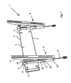
- Fig. 1-3B show views of a first embodiment of the device 1 according to the invention, which device 1 is provided with an elongated wall element 2, which is to be fastened via fastening holes 3 on a wall.
- the wall element 2 is provided with two mutually parallel and horizontally extending edges 4, 5.
- the edge 4 is, as clearly shown in Fig. 4A, provided with a surface 6 which faces the wall and a forming acute angle with the wall.
- the edge 5 comprises a surface 7 which faces the wall and forms an acute angle with the wall.
- the device 1 is further provided with two support elements 8, which are each provided with a coupled to the wall element 2 support 9 and a pivotable about a pivot axis 10, connected to the support 10 profile 11.
- the supports 9 and the profile 11 are spaced from the pivot axis 10 by means of a connecting arm 12 connected to each other, with the aid of the connecting arm 12, the angle between the profile 11 and the support 9 can be adjusted.
- the support 9 is provided in the region of the upper side with a first hook-shaped element 13 which, as can be seen more clearly in FIG. 4A, is in engagement with the edge 4, the hook-shaped element 13 resting against the surface 6.
- the support 9 is provided on a side facing away from the first hook-shaped element 13 side with a carriage (see Fig. 2B . 3B ).
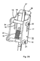
- the carriage 14 comprises two wall elements 15 extending parallel to one another and a wall element 16 extending therebetween.
- the two wall elements 15 are provided with L-shaped grooves 17 having a first recess 18 extending in the longitudinal direction of the carriage 14 and a transversely extending one second recess 19 include.
- the support 9 is provided with a carriage 20 extending vertically to the first hook-shaped element 13, in which a pivot axis 21 extending between the wall elements 15 of the carriage 14 is displaceable.
- the support 9 is further provided with a sliding axis 22 which is closer to the first hook-shaped element 13 of the support 9 than the pivot axis 21.
- the sliding axis 22 extends through the grooves 17 of the carriage 14. Between the sliding axis 22 and the pivot axis 21 extends a tension spring 23.
- the tension spring 23 can be seen in a position released from the sliding axle 22. In use, however, the tension spring 23 is connected to the sliding axle 22 as well as in FIG Fig. 3B shows.
- the object such as a screen to a wall
- at least one support element 8 and in the here shown Embodiment two support elements 8 attached to a screen To attach the object, such as a screen to a wall, at least one support element 8 and in the here shown Embodiment two support elements 8 attached to a screen.
- the profiles 11 are provided with recesses through which, for example, screws can be pushed.
- Each type of screen such as an LCD or plasma screen, has fixed mounting holes on the back that can be rearranged on each screen. Since the profile itself is provided with a series of holes, a profile 11 can be attached to each screen. However, the distance between two adjacent profiles 11 may vary depending on the screen. However, this causes no problems in the device according to the invention. In the device described above and known from the US patent, the profiles must be mounted in a distance determined by the wall element from each other.
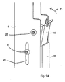
- the screen After attaching the support member 8 to the screen and attaching the wall member 2 to the wall, the screen is gripped by a user and the first hook-shaped members 13 are positioned around the first catch member 4 by the user, thereby forming the screen by means of the first hook-shaped members 13 at the edge 4 hangs. Because the edge is elongate, the first hook-shaped elements 13 of the two supports 9 can be connected to the wall element 2 over a large area. An exact alignment of the hook-shaped elements 13 with respect to the wall element 2 is therefore not necessary. Before the hook-shaped elements 13 are connected to the edge 4, each carriage 14 in the in Fig. 2A . 2 B shown position, whereby the tension spring 23 is pulled out and brought under bias.
- the sliding axis 22 is in this case at one end 24 of the second recess 19 of the L-shaped groove 17. Further, the carriage 14 is in a pivoted position, the wall 16 is pivoted from the profile 11 to the wall element 2 out.
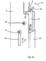
- the wall element 16 in this case extends past a wall 25 of the support 9. After the first hook-shaped elements 13 have been brought into engagement with the edge 4, the underside of the screen and therefore the undersides of the supports 9 in a pivoted to the wall Pivoted direction, whereby one end of a surface 26 of the wall element 16 abuts against the wall. The end of the surface 26 forms a stop surface.
- the surface 26 acts as a second hook-shaped element.
- the support 9 is now firmly attached to the wall element 2. If the support 9, for example, by unauthorized persons in an upward direction, this displacement is limited by stop surfaces 91, which are located at such a short distance to the first hook-shaped element 13, that the removal of the support 9 from the wall element 2 is not possible ,
Landscapes
- Engineering & Computer Science (AREA)
- General Engineering & Computer Science (AREA)
- Mechanical Engineering (AREA)
- Supports Or Holders For Household Use (AREA)
- Casings For Electric Apparatus (AREA)
- Connection Of Plates (AREA)
- Mirrors, Picture Frames, Photograph Stands, And Related Fastening Devices (AREA)
Claims (10)
- Appareil (1) destiné à fixer un écran à un mur, l'appareil (1) étant pourvu d'un élément mural (2) à fixer au mur et d'un élément de soutien (8) à fixer à l'écran, l'élément de soutien (8) étant pourvu d'un premier élément en forme de crochet (13) qui peut être fixé en fonctionnement à un premier élément récepteur (4) prévu dans l'élément mural, l'élément de soutien (8) étant pourvu par rapport au premier élément en forme de crochet, d'un second élément en forme de crochet qui peut être déplacé contre une résistance en direction de l'élément en forme de crochet (13), le second élément en forme de crochet se trouvant en engagement avec le second élément récepteur (5) prévu dans l'élément mural en fonctionnement contre une résistance, caractérisé en ce que l'appareil (1) est pourvu d'un moyen de blocage pour le blocage du second élément en forme de crochet (26) dans une position de blocage dans une position détachée de l'élément mural et en ce que le second élément en forme de crochet comporte un chariot (14) qui est logé de manière mobile et pivotante par rapport à l'élément de soutien (8), le chariot (14) pouvant être déplacé d'une première position détachée de l'élément mural (2) à une seconde position reliée au second élément récepteur (5) et inversement, le chariot (14) étant placé dans la première position contre une résistance à distance du premier élément en forme de crochet (13) et étant pivoté par rapport à l'élément mural (2), alors que le chariot (14) est pivoté à cause du pivotement du côté inférieur de l'écran et par conséquent de l'élément de soutien dans un sens pivoté vers le mur dans la seconde position loin de l'élément mural (2) et est poussé vers le premier élément en forme de crochet (13).
- Appareil (1) selon la revendication 1, caractérisé en ce que le chariot (14) est pourvu d'un axe de pivotement (21) qui est logé de manière mobile dans une rainure (20) s'étendant vers le premier élément en forme de crochet (13) dans l'élément de soutien (8), la rainure (20) étant de plus pourvue d'une rainure en forme de L (17), dans laquelle un axe de coulissement (22) relié à l'élément de soutien (8) se trouve, lequel chariot (14) peut être pivoté autour de l'axe de pivotement (21) de la première position, dans laquelle l'axe de coulissement (22) se trouve dans la zone d'une première extrémité de la rainure en forme de L (17), à une seconde position, dans laquelle l'axe de coulissement (22) se trouve dans la zone d'une seconde extrémité de la rainure en forme de L (17) et inversement.
- Appareil (1) selon la revendication 2, caractérisé en ce que l'axe de coulissement (22) se trouve plus près du premier élément en forme de crochet (13) que l'axe de pivotement (21), un ressort de traction (23) s'étendant entre l'axe de pivotement (21) et l'axe de coulissement (22).
- Appareil (1) selon l'une quelconque des revendications précédentes, caractérisé en ce que le chariot (14) est pourvu, sur un côté éloigné de l'axe de pivotement (21), d'une surface de butée, le chariot (14) étant pivoté autour de l'axe de pivotement (21) en fonctionnement par un contact entre la surface de butée et l'élément mural (2) et/ou le mur.
- Appareil (1) selon l'une quelconque des revendications précédentes, caractérisé en ce que le chariot peut être pivoté dans la position de blocage.
- Appareil (1) selon l'une quelconque des revendications précédentes, caractérisé en ce que le second élément en forme de crochet peut être relié à un élément de traction afin de déplacer le second élément en forme de crochet contre la résistance dans une direction éloignée du premier élément en forme de crochet.
- Appareil (1) selon l'une quelconque des revendications précédentes, caractérisé en ce que le premier et/ou le second élément récepteur comporte un bord étiré en longueur (4, 5), avec lequel l'élément en forme de crochet (13, 26) se trouve en engagement en fonctionnement, la longueur du bord étiré en longueur (4, 5) étant au moins deux fois plus grande que la largeur de l'élément en forme de crochet (13, 26).
- Appareil (1) selon l'une quelconque des revendications précédentes, caractérisé en ce que le second élément récepteur comporte une bande (55) étirée en longueur qui est logée de manière mobile dans l'élément mural (2), laquelle bande (55) peut être déplacée d'une position de réception, dans laquelle le second élément en forme de crochet est à amener en engagement avec la bande (55), à une position de libération, dans laquelle le second élément récepteur est désengagé de la bande.
- Appareil (1) selon la revendication 8, caractérisé en ce que la bande (55) peut être verrouillée à l'élément mural (2).
- Elément de soutien (8) destiné à être utilisé dans un appareil (1) qui convient à la fixation d'un écran à un mur, l'appareil (1) étant pourvu d'un élément mural (2) à fixer au mur et de l'élément de soutien (8) à fixer à l'écran, lequel élément de soutien (8) est pourvu d'un premier élément en forme de crochet (13) qui peut être fixé en fonctionnement à un premier élément récepteur (4) prévu dans un élément mural, l'élément de soutien (8) étant pourvu, par rapport au premier élément en forme de crochet, d'un second élément en forme de crochet (26) qui peut être déplacé contre une résistance en direction du premier élément en forme de crochet (13), le second élément en forme de crochet se trouvant en engagement avec le second élément récepteur (5) prévu dans l'élément mural en fonctionnement contre une résistance, caractérisé en ce que l'élément de soutien (8) est pourvu d'un moyen de blocage pour le blocage du second élément en forme de crochet (26) dans une position de blocage dans une position détachée de l'élément mural et en ce que le second élément en forme de crochet comporte un chariot (14) qui est logé de manière mobile et pivotante par rapport à l'élément de soutien (8), le chariot (14) pouvant être déplacé d'une première position détachée de l'élément mural (2) à une seconde position reliée au second élément récepteur (5) et inversement, le chariot (14) étant placé dans la première position contre une résistance à distance du premier élément en forme de crochet (13) et étant pivoté par rapport à l'élément mural (2), alors que le chariot (14) est pivoté à cause du pivotement du côté inférieur de l'écran et par conséquent de l'élément de soutien dans une direction pivotée vers le mur à la seconde position loin de l'élément mural (2) et est poussé vers le premier élément en forme de crochet (13).
Priority Applications (1)
| Application Number | Priority Date | Filing Date | Title |
|---|---|---|---|
| US12/689,768 US8262044B2 (en) | 2008-01-28 | 2010-01-19 | Device suitable for securing an object to a wall |
Applications Claiming Priority (1)
| Application Number | Priority Date | Filing Date | Title |
|---|---|---|---|
| NL1034966A NL1034966C2 (nl) | 2008-01-28 | 2008-01-28 | Inrichting geschikt voor het bevestigen van een object aan een wand alsmede wanddeel en ondersteuningsdeel geschikt voor een dergelijke inrichting. |
Publications (2)
| Publication Number | Publication Date |
|---|---|
| EP2083208A1 EP2083208A1 (fr) | 2009-07-29 |
| EP2083208B1 true EP2083208B1 (fr) | 2011-06-15 |
Family
ID=39811846
Family Applications (1)
| Application Number | Title | Priority Date | Filing Date |
|---|---|---|---|
| EP09000907A Active EP2083208B1 (fr) | 2008-01-28 | 2009-01-23 | Appareil, destiné à fixer un objet à un mur, ainsi qu'un élément mural et un élément de soutien qui sont adaptés à un tel appareil |
Country Status (5)
| Country | Link |
|---|---|
| US (1) | US8262044B2 (fr) |
| EP (1) | EP2083208B1 (fr) |
| AT (1) | ATE513160T1 (fr) |
| DE (1) | DE202009000978U1 (fr) |
| NL (1) | NL1034966C2 (fr) |
Cited By (2)
| Publication number | Priority date | Publication date | Assignee | Title |
|---|---|---|---|---|
| US11191178B2 (en) | 2019-01-24 | 2021-11-30 | Steelcase Inc. | Display support system and method for the use thereof |
| US11647834B2 (en) | 2020-07-23 | 2023-05-16 | Steelcase Inc. | Display support system and method for the use thereof |
Families Citing this family (33)
| Publication number | Priority date | Publication date | Assignee | Title |
|---|---|---|---|---|
| JP5303582B2 (ja) * | 2011-01-13 | 2013-10-02 | 株式会社ソニー・コンピュータエンタテインメント | 携帯端末装置および通信切替方法 |
| CN102168788B (zh) * | 2011-03-21 | 2013-01-09 | 宁波音王电声股份有限公司 | 一种带锁定功能的平板电视支架 |
| US8746642B2 (en) * | 2012-02-15 | 2014-06-10 | Peerless Industries, Inc. | Mounting system for use with audio/visual devices or the like |
| TWM437911U (en) * | 2012-05-22 | 2012-09-21 | Ming-Hsien Huang | Suspending apparatus |
| FR2991150B1 (fr) | 2012-06-01 | 2015-06-26 | Erard | Support d'ecran |
| CN103133836B (zh) * | 2013-03-06 | 2015-01-14 | 宁波一舟精密机械制造有限公司 | 平板电视壁挂架 |
| CN103277649A (zh) * | 2013-05-23 | 2013-09-04 | 裴旭波 | 棘轮调节电视机架 |
| US9829151B1 (en) * | 2014-01-21 | 2017-11-28 | Mw Products Llc | Height adjustable flat panel display mounts |
| US9897250B1 (en) * | 2014-02-07 | 2018-02-20 | American Megatrends, Inc. | Wall mount system with brackets coupled to wall plate track by rotatable securement device |
| US9303811B1 (en) * | 2014-02-11 | 2016-04-05 | Cisco Technology, Inc. | Configurable mounting bracket for mounting rail installations |
| CN103939717B (zh) * | 2014-04-28 | 2017-01-18 | 乐歌人体工学科技股份有限公司 | 曲面电视壁挂架 |
| US10024490B2 (en) | 2014-04-30 | 2018-07-17 | Peerless Industries, Inc. | Video wall mount |
| US12152720B1 (en) * | 2017-04-17 | 2024-11-26 | Manehu Product Alliance, Llc | Adjustable mounting systems for televisions |
| USD911320S1 (en) * | 2019-08-20 | 2021-02-23 | Yaqi Lyu | Monitor wall mount apparatus |
| CN211175957U (zh) * | 2019-09-23 | 2020-08-04 | 裴旭波 | 一种调节装置 |
| USD913998S1 (en) * | 2019-11-01 | 2021-03-23 | Xinadda (Hong Kong) Limited | TV mount bracket |
| USD905070S1 (en) * | 2019-11-01 | 2020-12-15 | Xinadda (Hong Kong) Limited | TV mount bracket |
| CN112824735A (zh) * | 2019-11-20 | 2021-05-21 | 青岛海信商用显示股份有限公司 | 支架和显示设备总成 |
| USD1023019S1 (en) * | 2019-12-06 | 2024-04-16 | CKnapp Sales, Inc. | Monitor stand |
| CN111981262A (zh) * | 2020-08-06 | 2020-11-24 | 华升智能科技(广州)有限公司 | 一种显示屏自动伸出与收回装置 |
| USD950529S1 (en) * | 2020-09-16 | 2022-05-03 | Vogel's Ip B.V. | Wall mount tilt support |
| NL2028635B1 (nl) | 2021-07-06 | 2023-01-12 | Vogels Ip B V | Systeem voor het positioneren van een beeldscherm. |
| CN113531348A (zh) * | 2021-08-20 | 2021-10-22 | 深圳创维-Rgb电子有限公司 | 伸缩挂架机构和显示装置 |
| US11708938B2 (en) * | 2021-09-21 | 2023-07-25 | Gem Products, Llc | Foldable bracket |
| FR3134162B1 (fr) | 2022-04-04 | 2024-03-01 | Erard | Dispositif de fixation d’un écran à un support |
| KR102520148B1 (ko) * | 2022-09-29 | 2023-04-10 | 권경록 | 벽걸이용 디스플레이 장치 거치대 |
| CN116255548A (zh) * | 2022-12-29 | 2023-06-13 | 深圳市倍思奇创新科技有限公司 | 用于显示器支架的弹簧平衡垂直倾斜机构 |
| CN116255527A (zh) * | 2022-12-29 | 2023-06-13 | 深圳市倍思奇创新科技有限公司 | 带偏心齿轮的显示器支架垂直倾斜机构 |
| US12163621B2 (en) * | 2022-12-30 | 2024-12-10 | Xinadda (Shen Zhen) Products Co., Ltd | Adjustable mount for display screen |
| CN220471288U (zh) * | 2023-07-12 | 2024-02-09 | 兴先达(香港)有限公司 | 显示屏安装支架 |
| TWI881427B (zh) * | 2023-08-15 | 2025-04-21 | 啟碁科技股份有限公司 | 支架結構、支架模組及壁掛模組 |
| US12571495B2 (en) * | 2023-11-24 | 2026-03-10 | Xinadda (Hong Kong) Limited | Display mounting support |
| USD1075774S1 (en) * | 2024-01-24 | 2025-05-20 | Xinadda (Hong Kong) Limited | Tilting mount for televisions |
Citations (1)
| Publication number | Priority date | Publication date | Assignee | Title |
|---|---|---|---|---|
| DE20107212U1 (de) * | 2000-10-06 | 2001-08-02 | Ulamo Beheer B.V., Ulft | Haltevorrichtung |
Family Cites Families (22)
| Publication number | Priority date | Publication date | Assignee | Title |
|---|---|---|---|---|
| US2935286A (en) * | 1956-01-27 | 1960-05-03 | Parsons Jim Skelt | Infusion standard |
| GB2148097A (en) * | 1983-10-21 | 1985-05-30 | John Charles Wells | Radiator securing means |
| DE3915514A1 (de) | 1989-05-12 | 1990-11-15 | Dambach Werke Gmbh | Haltevorrichtung |
| DE19963380A1 (de) | 1999-12-28 | 2001-07-12 | Nokia Mobile Phones Ltd | Kombination |
| KR100406487B1 (ko) * | 2001-06-05 | 2003-11-17 | 엘지전자 주식회사 | 벽걸이용 디스플레이 장치의 고정 및 각도 조절장치 |
| KR100377629B1 (ko) | 2001-06-05 | 2003-03-26 | 엘지전자 주식회사 | 벽걸이용 디스플레이 장치의 각도 조절장치 |
| CH696277A5 (de) | 2003-05-15 | 2007-03-15 | Alpe Alpenengineering Siegenth | Verfahren zum wieder entnehmbaren Befestigen eines Dienstleistungsautomaten in einer vertikalen Lage sowie Anordnung hierzu. |
| US7270309B2 (en) | 2004-01-08 | 2007-09-18 | Vantage Point Products Corp. | Apparatus for mounting a flat panel display |
| GB2410599B (en) * | 2004-01-30 | 2006-01-04 | Peter Ligertwood | Panel mounting unit |
| TWI274110B (en) * | 2004-12-16 | 2007-02-21 | Ming-Hsien Huang | Hanging rack device for thin type electronic equipment |
| KR100609876B1 (ko) * | 2005-03-08 | 2006-08-08 | 삼성전자주식회사 | 디스플레이 장치용 월 마운트 |
| JP4212569B2 (ja) * | 2005-04-01 | 2009-01-21 | 株式会社デンソー | スイッチング装置 |
| KR100743746B1 (ko) * | 2005-07-08 | 2007-07-27 | 엘지전자 주식회사 | 디스플레이 기기의 각도 조절 장치 |
| US7722002B2 (en) * | 2006-04-11 | 2010-05-25 | Peerless Industries, Inc. | Movable extension assembly for a mounting system |
| TWM299816U (en) * | 2006-05-12 | 2006-10-21 | Seng-Ling Tan | Hanging stand capable of adjusting angle for plasma television |
| DE202006011519U1 (de) * | 2006-07-27 | 2006-11-09 | K.H.S. MUSICAL INSTRUMENT CO., LTD., Lu Chou City | Aufhängevorrichtung |
| US7963489B2 (en) * | 2006-08-10 | 2011-06-21 | Peerless Industries, Inc. | Extension mechanism for a mounting system |
| US7871048B2 (en) * | 2006-12-28 | 2011-01-18 | Bell'o International Corp. | Flat panel display mounting system |
| GB2449129B (en) * | 2007-05-11 | 2011-11-23 | Path Distrib Ltd | Improvements in tiltable wall mounts |
| CA2698385C (fr) * | 2007-09-06 | 2015-11-24 | Milestone AV Technologies, LLC | Systeme de montage mural d'affichage avec loquet a ressort elastomere et fonction d'ajustement de hauteur et de reglage de niveau post-installation |
| DE202007014537U1 (de) * | 2007-10-17 | 2008-04-03 | REIGN POWER CO., LTD., Hsinchuang City | Struktur zur automatischen Montage an einer Montageschiene |
| NL1034965C2 (nl) * | 2008-01-28 | 2009-07-30 | Vogel S Holding Bv | Inrichting geschikt voor het kantelbaar aan een wand bevestigen van een beeldscherm alsmede een dergelijke werkwijze. |
-
2008
- 2008-01-28 NL NL1034966A patent/NL1034966C2/nl not_active IP Right Cessation
-
2009
- 2009-01-23 AT AT09000907T patent/ATE513160T1/de active
- 2009-01-23 EP EP09000907A patent/EP2083208B1/fr active Active
- 2009-01-26 DE DE202009000978U patent/DE202009000978U1/de not_active Expired - Lifetime
-
2010
- 2010-01-19 US US12/689,768 patent/US8262044B2/en not_active Expired - Fee Related
Patent Citations (1)
| Publication number | Priority date | Publication date | Assignee | Title |
|---|---|---|---|---|
| DE20107212U1 (de) * | 2000-10-06 | 2001-08-02 | Ulamo Beheer B.V., Ulft | Haltevorrichtung |
Cited By (4)
| Publication number | Priority date | Publication date | Assignee | Title |
|---|---|---|---|---|
| US11191178B2 (en) | 2019-01-24 | 2021-11-30 | Steelcase Inc. | Display support system and method for the use thereof |
| US11903158B2 (en) | 2019-01-24 | 2024-02-13 | Steelcase Inc. | Display support system and method for the use thereof |
| US12444330B2 (en) | 2019-01-24 | 2025-10-14 | Steelcase Inc. | Display support system and method for the use thereof |
| US11647834B2 (en) | 2020-07-23 | 2023-05-16 | Steelcase Inc. | Display support system and method for the use thereof |
Also Published As
| Publication number | Publication date |
|---|---|
| NL1034966C2 (nl) | 2009-07-30 |
| US8262044B2 (en) | 2012-09-11 |
| DE202009000978U1 (de) | 2009-04-30 |
| EP2083208A1 (fr) | 2009-07-29 |
| US20100187385A1 (en) | 2010-07-29 |
| ATE513160T1 (de) | 2011-07-15 |
Similar Documents
| Publication | Publication Date | Title |
|---|---|---|
| EP2083208B1 (fr) | Appareil, destiné à fixer un objet à un mur, ainsi qu'un élément mural et un élément de soutien qui sont adaptés à un tel appareil | |
| EP2205126B1 (fr) | Dispositif de montage d'une unité de guidage, partie de meuble et meuble comprenant un tel dispositif | |
| EP3291706B1 (fr) | Meuble et procédé pour immobiliser une pièce de meuble mobile | |
| DE102006032965B4 (de) | Stützrahmenstruktur | |
| AT519077B1 (de) | Vorrichtung zur lösbaren Befestigung einer Frontblende an einem Schubkasten und Verfahren zur Montage oder Demontage einer Frontblende an einem Schubkasten | |
| DE102013104829A1 (de) | Auszugsführung | |
| EP0694320A2 (fr) | Dispositif sur un ski | |
| EP3713448B1 (fr) | Dispositif de fixation d'un tiroir et meuble | |
| DE202010007428U1 (de) | Verbindungsvorrichtung und Schublade mit einer Verbindungsvorrichtung | |
| EP3684223B1 (fr) | Dispositif d'accouplement destiné à un tiroir à encliquetage postérieur | |
| DE69503828T2 (de) | Blokiervorrichtung für eine Verlängerung Bezüglich eines Möbelstückes, und Möbelstück damit Ausgestattet | |
| EP3923767B1 (fr) | Tiroir | |
| EP2233039B1 (fr) | Guidage pour tiroirs | |
| DE202023104791U1 (de) | Gleithülsenstruktur | |
| EP3009043B1 (fr) | Tiroir coulissant avec un dispositif de reglage pour l'alignement du panneau frontal | |
| EP2301383B1 (fr) | Elément de liaison, cadre de meuble, bloc pour l'assemblage d'un support de meuble et système modulaire pour l'assemblage d'une pièce de meuble | |
| EP3860400B1 (fr) | Dispositif de fixation servant à fixer un panneau d'un tiroir sur un châssis | |
| DE202013004939U1 (de) | Vorrichtung zur Positionierung und Fixierung eines beweglichen Möbelteils | |
| EP2182788A1 (fr) | Agencement de retenue pour un module de tiroir et bâti de support | |
| DE202009014693U1 (de) | Beschlaganordnung | |
| DE202012005260U1 (de) | Monitorpositionierungsvorrichtung | |
| WO2015104109A1 (fr) | Ensemble boîtier | |
| EP2730196B1 (fr) | Dispositif permettant de fixer une partie avant à une partie latérale d'une pièce de meuble mobile | |
| EP3860402B1 (fr) | Dispositif de fixation servant à fixer un panneau d'un tiroir sur un châssis | |
| EP3965614B1 (fr) | Agencement de fixation avec un fond de tiroir et procédé de montage d'un fond de tiroir |
Legal Events
| Date | Code | Title | Description |
|---|---|---|---|
| PUAI | Public reference made under article 153(3) epc to a published international application that has entered the european phase |
Free format text: ORIGINAL CODE: 0009012 |
|
| AK | Designated contracting states |
Kind code of ref document: A1 Designated state(s): AT BE BG CH CY CZ DE DK EE ES FI FR GB GR HR HU IE IS IT LI LT LU LV MC MK MT NL NO PL PT RO SE SI SK TR |
|
| AX | Request for extension of the european patent |
Extension state: AL BA RS |
|
| 17P | Request for examination filed |
Effective date: 20100121 |
|
| 17Q | First examination report despatched |
Effective date: 20100222 |
|
| AKX | Designation fees paid |
Designated state(s): AT BE BG CH CY CZ DE DK EE ES FI FR GB GR HR HU IE IS IT LI LT LU LV MC MK MT NL NO PL PT RO SE SI SK TR |
|
| GRAP | Despatch of communication of intention to grant a patent |
Free format text: ORIGINAL CODE: EPIDOSNIGR1 |
|
| GRAS | Grant fee paid |
Free format text: ORIGINAL CODE: EPIDOSNIGR3 |
|
| GRAA | (expected) grant |
Free format text: ORIGINAL CODE: 0009210 |
|
| AK | Designated contracting states |
Kind code of ref document: B1 Designated state(s): AT BE BG CH CY CZ DE DK EE ES FI FR GB GR HR HU IE IS IT LI LT LU LV MC MK MT NL NO PL PT RO SE SI SK TR |
|
| REG | Reference to a national code |
Ref country code: CH Ref legal event code: EP Ref country code: GB Ref legal event code: FG4D Free format text: NOT ENGLISH |
|
| REG | Reference to a national code |
Ref country code: IE Ref legal event code: FG4D Free format text: LANGUAGE OF EP DOCUMENT: GERMAN |
|
| REG | Reference to a national code |
Ref country code: DE Ref legal event code: R096 Ref document number: 502009000760 Country of ref document: DE Effective date: 20110728 |
|
| REG | Reference to a national code |
Ref country code: NL Ref legal event code: T3 |
|
| PG25 | Lapsed in a contracting state [announced via postgrant information from national office to epo] |
Ref country code: NO Free format text: LAPSE BECAUSE OF FAILURE TO SUBMIT A TRANSLATION OF THE DESCRIPTION OR TO PAY THE FEE WITHIN THE PRESCRIBED TIME-LIMIT Effective date: 20110915 Ref country code: LT Free format text: LAPSE BECAUSE OF FAILURE TO SUBMIT A TRANSLATION OF THE DESCRIPTION OR TO PAY THE FEE WITHIN THE PRESCRIBED TIME-LIMIT Effective date: 20110615 Ref country code: SE Free format text: LAPSE BECAUSE OF FAILURE TO SUBMIT A TRANSLATION OF THE DESCRIPTION OR TO PAY THE FEE WITHIN THE PRESCRIBED TIME-LIMIT Effective date: 20110615 Ref country code: HR Free format text: LAPSE BECAUSE OF FAILURE TO SUBMIT A TRANSLATION OF THE DESCRIPTION OR TO PAY THE FEE WITHIN THE PRESCRIBED TIME-LIMIT Effective date: 20110615 |
|
| PG25 | Lapsed in a contracting state [announced via postgrant information from national office to epo] |
Ref country code: FI Free format text: LAPSE BECAUSE OF FAILURE TO SUBMIT A TRANSLATION OF THE DESCRIPTION OR TO PAY THE FEE WITHIN THE PRESCRIBED TIME-LIMIT Effective date: 20110615 Ref country code: SI Free format text: LAPSE BECAUSE OF FAILURE TO SUBMIT A TRANSLATION OF THE DESCRIPTION OR TO PAY THE FEE WITHIN THE PRESCRIBED TIME-LIMIT Effective date: 20110615 Ref country code: LV Free format text: LAPSE BECAUSE OF FAILURE TO SUBMIT A TRANSLATION OF THE DESCRIPTION OR TO PAY THE FEE WITHIN THE PRESCRIBED TIME-LIMIT Effective date: 20110615 Ref country code: GR Free format text: LAPSE BECAUSE OF FAILURE TO SUBMIT A TRANSLATION OF THE DESCRIPTION OR TO PAY THE FEE WITHIN THE PRESCRIBED TIME-LIMIT Effective date: 20110916 Ref country code: CY Free format text: LAPSE BECAUSE OF FAILURE TO SUBMIT A TRANSLATION OF THE DESCRIPTION OR TO PAY THE FEE WITHIN THE PRESCRIBED TIME-LIMIT Effective date: 20110615 |
|
| REG | Reference to a national code |
Ref country code: IE Ref legal event code: FD4D |
|
| PG25 | Lapsed in a contracting state [announced via postgrant information from national office to epo] |
Ref country code: IS Free format text: LAPSE BECAUSE OF FAILURE TO SUBMIT A TRANSLATION OF THE DESCRIPTION OR TO PAY THE FEE WITHIN THE PRESCRIBED TIME-LIMIT Effective date: 20111015 Ref country code: PT Free format text: LAPSE BECAUSE OF FAILURE TO SUBMIT A TRANSLATION OF THE DESCRIPTION OR TO PAY THE FEE WITHIN THE PRESCRIBED TIME-LIMIT Effective date: 20111017 Ref country code: IE Free format text: LAPSE BECAUSE OF FAILURE TO SUBMIT A TRANSLATION OF THE DESCRIPTION OR TO PAY THE FEE WITHIN THE PRESCRIBED TIME-LIMIT Effective date: 20110615 Ref country code: CZ Free format text: LAPSE BECAUSE OF FAILURE TO SUBMIT A TRANSLATION OF THE DESCRIPTION OR TO PAY THE FEE WITHIN THE PRESCRIBED TIME-LIMIT Effective date: 20110615 Ref country code: EE Free format text: LAPSE BECAUSE OF FAILURE TO SUBMIT A TRANSLATION OF THE DESCRIPTION OR TO PAY THE FEE WITHIN THE PRESCRIBED TIME-LIMIT Effective date: 20110615 |
|
| PG25 | Lapsed in a contracting state [announced via postgrant information from national office to epo] |
Ref country code: PL Free format text: LAPSE BECAUSE OF FAILURE TO SUBMIT A TRANSLATION OF THE DESCRIPTION OR TO PAY THE FEE WITHIN THE PRESCRIBED TIME-LIMIT Effective date: 20110615 Ref country code: SK Free format text: LAPSE BECAUSE OF FAILURE TO SUBMIT A TRANSLATION OF THE DESCRIPTION OR TO PAY THE FEE WITHIN THE PRESCRIBED TIME-LIMIT Effective date: 20110615 Ref country code: RO Free format text: LAPSE BECAUSE OF FAILURE TO SUBMIT A TRANSLATION OF THE DESCRIPTION OR TO PAY THE FEE WITHIN THE PRESCRIBED TIME-LIMIT Effective date: 20110615 |
|
| PLBE | No opposition filed within time limit |
Free format text: ORIGINAL CODE: 0009261 |
|
| STAA | Information on the status of an ep patent application or granted ep patent |
Free format text: STATUS: NO OPPOSITION FILED WITHIN TIME LIMIT |
|
| 26N | No opposition filed |
Effective date: 20120316 |
|
| PG25 | Lapsed in a contracting state [announced via postgrant information from national office to epo] |
Ref country code: IT Free format text: LAPSE BECAUSE OF FAILURE TO SUBMIT A TRANSLATION OF THE DESCRIPTION OR TO PAY THE FEE WITHIN THE PRESCRIBED TIME-LIMIT Effective date: 20110615 |
|
| PG25 | Lapsed in a contracting state [announced via postgrant information from national office to epo] |
Ref country code: DK Free format text: LAPSE BECAUSE OF FAILURE TO SUBMIT A TRANSLATION OF THE DESCRIPTION OR TO PAY THE FEE WITHIN THE PRESCRIBED TIME-LIMIT Effective date: 20110615 |
|
| REG | Reference to a national code |
Ref country code: DE Ref legal event code: R097 Ref document number: 502009000760 Country of ref document: DE Effective date: 20120316 |
|
| BERE | Be: lapsed |
Owner name: VOGEL'S HOLDING B.V. Effective date: 20120131 |
|
| PG25 | Lapsed in a contracting state [announced via postgrant information from national office to epo] |
Ref country code: MC Free format text: LAPSE BECAUSE OF NON-PAYMENT OF DUE FEES Effective date: 20120131 |
|
| PG25 | Lapsed in a contracting state [announced via postgrant information from national office to epo] |
Ref country code: BE Free format text: LAPSE BECAUSE OF NON-PAYMENT OF DUE FEES Effective date: 20120131 |
|
| PG25 | Lapsed in a contracting state [announced via postgrant information from national office to epo] |
Ref country code: MK Free format text: LAPSE BECAUSE OF FAILURE TO SUBMIT A TRANSLATION OF THE DESCRIPTION OR TO PAY THE FEE WITHIN THE PRESCRIBED TIME-LIMIT Effective date: 20110615 |
|
| PG25 | Lapsed in a contracting state [announced via postgrant information from national office to epo] |
Ref country code: ES Free format text: LAPSE BECAUSE OF FAILURE TO SUBMIT A TRANSLATION OF THE DESCRIPTION OR TO PAY THE FEE WITHIN THE PRESCRIBED TIME-LIMIT Effective date: 20110926 |
|
| PG25 | Lapsed in a contracting state [announced via postgrant information from national office to epo] |
Ref country code: BG Free format text: LAPSE BECAUSE OF FAILURE TO SUBMIT A TRANSLATION OF THE DESCRIPTION OR TO PAY THE FEE WITHIN THE PRESCRIBED TIME-LIMIT Effective date: 20110915 |
|
| PG25 | Lapsed in a contracting state [announced via postgrant information from national office to epo] |
Ref country code: MT Free format text: LAPSE BECAUSE OF FAILURE TO SUBMIT A TRANSLATION OF THE DESCRIPTION OR TO PAY THE FEE WITHIN THE PRESCRIBED TIME-LIMIT Effective date: 20110615 |
|
| REG | Reference to a national code |
Ref country code: CH Ref legal event code: PL |
|
| GBPC | Gb: european patent ceased through non-payment of renewal fee |
Effective date: 20130123 |
|
| PG25 | Lapsed in a contracting state [announced via postgrant information from national office to epo] |
Ref country code: CH Free format text: LAPSE BECAUSE OF NON-PAYMENT OF DUE FEES Effective date: 20130131 Ref country code: LI Free format text: LAPSE BECAUSE OF NON-PAYMENT OF DUE FEES Effective date: 20130131 |
|
| PG25 | Lapsed in a contracting state [announced via postgrant information from national office to epo] |
Ref country code: GB Free format text: LAPSE BECAUSE OF NON-PAYMENT OF DUE FEES Effective date: 20130123 |
|
| PG25 | Lapsed in a contracting state [announced via postgrant information from national office to epo] |
Ref country code: TR Free format text: LAPSE BECAUSE OF FAILURE TO SUBMIT A TRANSLATION OF THE DESCRIPTION OR TO PAY THE FEE WITHIN THE PRESCRIBED TIME-LIMIT Effective date: 20110615 |
|
| PG25 | Lapsed in a contracting state [announced via postgrant information from national office to epo] |
Ref country code: LU Free format text: LAPSE BECAUSE OF NON-PAYMENT OF DUE FEES Effective date: 20120123 |
|
| PG25 | Lapsed in a contracting state [announced via postgrant information from national office to epo] |
Ref country code: HU Free format text: LAPSE BECAUSE OF FAILURE TO SUBMIT A TRANSLATION OF THE DESCRIPTION OR TO PAY THE FEE WITHIN THE PRESCRIBED TIME-LIMIT Effective date: 20090123 |
|
| REG | Reference to a national code |
Ref country code: FR Ref legal event code: PLFP Year of fee payment: 7 |
|
| REG | Reference to a national code |
Ref country code: AT Ref legal event code: MM01 Ref document number: 513160 Country of ref document: AT Kind code of ref document: T Effective date: 20140123 |
|
| PG25 | Lapsed in a contracting state [announced via postgrant information from national office to epo] |
Ref country code: AT Free format text: LAPSE BECAUSE OF NON-PAYMENT OF DUE FEES Effective date: 20140123 |
|
| REG | Reference to a national code |
Ref country code: FR Ref legal event code: PLFP Year of fee payment: 8 |
|
| REG | Reference to a national code |
Ref country code: FR Ref legal event code: PLFP Year of fee payment: 9 |
|
| REG | Reference to a national code |
Ref country code: FR Ref legal event code: PLFP Year of fee payment: 10 |
|
| REG | Reference to a national code |
Ref country code: NL Ref legal event code: PD Owner name: VOGEL'S IP B.V.; NL Free format text: DETAILS ASSIGNMENT: CHANGE OF OWNER(S), ASSIGNMENT; FORMER OWNER NAME: VOGEL'S HOLDING B.V. Effective date: 20220516 |
|
| REG | Reference to a national code |
Ref country code: DE Ref legal event code: R081 Ref document number: 502009000760 Country of ref document: DE Owner name: VOGEL'S IP B.V., NL Free format text: FORMER OWNER: VOGEL'S HOLDING B.V., EINDHOVEN, NL Ref country code: DE Ref legal event code: R082 Ref document number: 502009000760 Country of ref document: DE Representative=s name: DENNEMEYER & ASSOCIATES S.A., DE Ref country code: DE Ref legal event code: R082 Ref document number: 502009000760 Country of ref document: DE Representative=s name: DENNEMEYER & ASSOCIATES RECHTSANWALTSGESELLSCH, DE |
|
| P01 | Opt-out of the competence of the unified patent court (upc) registered |
Effective date: 20230527 |
|
| REG | Reference to a national code |
Ref country code: DE Ref legal event code: R082 Ref document number: 502009000760 Country of ref document: DE Representative=s name: DENNEMEYER & ASSOCIATES RECHTSANWALTSGESELLSCH, DE |
|
| PGFP | Annual fee paid to national office [announced via postgrant information from national office to epo] |
Ref country code: NL Payment date: 20260121 Year of fee payment: 18 |
|
| PGFP | Annual fee paid to national office [announced via postgrant information from national office to epo] |
Ref country code: DE Payment date: 20260121 Year of fee payment: 18 |
|
| PGFP | Annual fee paid to national office [announced via postgrant information from national office to epo] |
Ref country code: FR Payment date: 20260123 Year of fee payment: 18 |