EP3291706B1 - Meuble et procédé pour immobiliser une pièce de meuble mobile - Google Patents
Meuble et procédé pour immobiliser une pièce de meuble mobile Download PDFInfo
- Publication number
- EP3291706B1 EP3291706B1 EP16721771.0A EP16721771A EP3291706B1 EP 3291706 B1 EP3291706 B1 EP 3291706B1 EP 16721771 A EP16721771 A EP 16721771A EP 3291706 B1 EP3291706 B1 EP 3291706B1
- Authority
- EP
- European Patent Office
- Prior art keywords
- item
- furniture
- clamping lever
- holding part
- clamping
- Prior art date
- Legal status (The legal status is an assumption and is not a legal conclusion. Google has not performed a legal analysis and makes no representation as to the accuracy of the status listed.)
- Active
Links
Images








Classifications
-
- A—HUMAN NECESSITIES
- A47—FURNITURE; DOMESTIC ARTICLES OR APPLIANCES; COFFEE MILLS; SPICE MILLS; SUCTION CLEANERS IN GENERAL
- A47B—TABLES; DESKS; OFFICE FURNITURE; CABINETS; DRAWERS; GENERAL DETAILS OF FURNITURE
- A47B88/00—Drawers for tables, cabinets or like furniture; Guides for drawers
- A47B88/40—Sliding drawers; Slides or guides therefor
- A47B88/423—Fastening devices for slides or guides
- A47B88/427—Fastening devices for slides or guides at drawer side
-
- A—HUMAN NECESSITIES
- A47—FURNITURE; DOMESTIC ARTICLES OR APPLIANCES; COFFEE MILLS; SPICE MILLS; SUCTION CLEANERS IN GENERAL
- A47B—TABLES; DESKS; OFFICE FURNITURE; CABINETS; DRAWERS; GENERAL DETAILS OF FURNITURE
- A47B88/00—Drawers for tables, cabinets or like furniture; Guides for drawers
- A47B88/40—Sliding drawers; Slides or guides therefor
- A47B88/407—Adjustably or detachably mounted drawers
-
- A—HUMAN NECESSITIES
- A47—FURNITURE; DOMESTIC ARTICLES OR APPLIANCES; COFFEE MILLS; SPICE MILLS; SUCTION CLEANERS IN GENERAL
- A47B—TABLES; DESKS; OFFICE FURNITURE; CABINETS; DRAWERS; GENERAL DETAILS OF FURNITURE
- A47B88/00—Drawers for tables, cabinets or like furniture; Guides for drawers
- A47B88/40—Sliding drawers; Slides or guides therefor
- A47B88/423—Fastening devices for slides or guides
- A47B88/427—Fastening devices for slides or guides at drawer side
- A47B2088/4272—Fastening devices for slides or guides at drawer side ensuring a correct connection at the moment when the drawer is coupled to the drawer rail
-
- A—HUMAN NECESSITIES
- A47—FURNITURE; DOMESTIC ARTICLES OR APPLIANCES; COFFEE MILLS; SPICE MILLS; SUCTION CLEANERS IN GENERAL
- A47B—TABLES; DESKS; OFFICE FURNITURE; CABINETS; DRAWERS; GENERAL DETAILS OF FURNITURE
- A47B88/00—Drawers for tables, cabinets or like furniture; Guides for drawers
- A47B88/40—Sliding drawers; Slides or guides therefor
- A47B88/423—Fastening devices for slides or guides
- A47B88/427—Fastening devices for slides or guides at drawer side
- A47B2088/4274—Fastening devices for slides or guides at drawer side the drawer being detachable as a whole from a slide frame
-
- A—HUMAN NECESSITIES
- A47—FURNITURE; DOMESTIC ARTICLES OR APPLIANCES; COFFEE MILLS; SPICE MILLS; SUCTION CLEANERS IN GENERAL
- A47B—TABLES; DESKS; OFFICE FURNITURE; CABINETS; DRAWERS; GENERAL DETAILS OF FURNITURE
- A47B88/00—Drawers for tables, cabinets or like furniture; Guides for drawers
- A47B88/40—Sliding drawers; Slides or guides therefor
- A47B88/423—Fastening devices for slides or guides
- A47B88/427—Fastening devices for slides or guides at drawer side
- A47B2088/4276—Fastening devices for slides or guides at drawer side at drawer front via latch means or locking lever
-
- A—HUMAN NECESSITIES
- A47—FURNITURE; DOMESTIC ARTICLES OR APPLIANCES; COFFEE MILLS; SPICE MILLS; SUCTION CLEANERS IN GENERAL
- A47B—TABLES; DESKS; OFFICE FURNITURE; CABINETS; DRAWERS; GENERAL DETAILS OF FURNITURE
- A47B88/00—Drawers for tables, cabinets or like furniture; Guides for drawers
- A47B88/40—Sliding drawers; Slides or guides therefor
- A47B88/423—Fastening devices for slides or guides
- A47B88/427—Fastening devices for slides or guides at drawer side
- A47B2088/4278—Quick-release clip
-
- A—HUMAN NECESSITIES
- A47—FURNITURE; DOMESTIC ARTICLES OR APPLIANCES; COFFEE MILLS; SPICE MILLS; SUCTION CLEANERS IN GENERAL
- A47B—TABLES; DESKS; OFFICE FURNITURE; CABINETS; DRAWERS; GENERAL DETAILS OF FURNITURE
- A47B2210/00—General construction of drawers, guides and guide devices
- A47B2210/0002—Guide construction for drawers
- A47B2210/0051—Guide position
- A47B2210/0056—Guide located at the bottom of the drawer
-
- A—HUMAN NECESSITIES
- A47—FURNITURE; DOMESTIC ARTICLES OR APPLIANCES; COFFEE MILLS; SPICE MILLS; SUCTION CLEANERS IN GENERAL
- A47B—TABLES; DESKS; OFFICE FURNITURE; CABINETS; DRAWERS; GENERAL DETAILS OF FURNITURE
- A47B2230/00—Furniture jointing; Furniture with such jointing
- A47B2230/0003—Adjustable furniture jointing
- A47B2230/0014—Height or width adjustment using eccenter mechanisms
Definitions
- the present invention relates to a piece of furniture according to the preamble of claim 1 and a method for fixing a movable furniture part.
- the EP 1 285 604 discloses a device for fixing a drawer to a rail of a pull-out guide, in which a base part which can be fastened to the drawer and a locking element which can be fixed on the pull-out guide are provided.
- the latching element can be displaced within certain tolerances relative to the base part. Due to the design of the locking element and the base part as a plastic part, the holding forces are limited, especially in the case of heavy drawers which are moved in the pull-out direction to the maximum pull-out position.
- the WO 2009/149479 discloses a device for releasably coupling a drawer with a pull-out guide, in which a holding part and a counter-holding part are connected to one another via an elastic piece of material. This leads to a reduction in the positional accuracy in the longitudinal direction. In the lateral direction, the drawer can be fixed to the rail using a locking device. In the standardized stop tests for drawers, in which the drawers are pulled out with a load, however, there are only comparatively low holding forces of such a latching connection.
- the DE 10 2011 000 724 A1 shows a workshop trolley in which a drawer can be locked in a closed position on a body.
- the locking mechanism comprises a web-shaped holder which can be locked to fix the drawer to a clamping eccentric.
- the US 2014/0314347 A1 discloses an adjustable coupling device for fixing a drawer to a pull-out guide.
- the piece of furniture according to the invention comprises a device for fixing a drawer with a clamping mechanism with a receptacle into which a web-shaped holding part can be inserted, a self-locking clamping lever being provided on the receptacle, by means of which the holding part is frictionally secured against being pulled out.
- a self-locking clamping lever of the clamping mechanism ensures that the holding part is held in such a way that it cannot be pulled further out of the receptacle in the opening direction.
- the movable furniture part is designed as a drawer.
- a frictional connection according to the invention differs from a positive connection in that the holding forces are provided by frictional forces and not by positive stop elements such as teeth or stops. As a result, a stepless adjustment can be obtained with a frictional fixation of the holding part, which is independent of stop elements.
- the web-shaped holding part can have a substantially flat surface for the frictional connection, which is in regions in contact with a contact surface on the clamping lever.
- the holding part can be made in the form of strips, angles, U-shaped, as a hollow profile or with other geometries, in particular made of metal, wherein a section of a profile can be used for the frictional connection.
- the holding part can also be formed by a section of the fitting profile.
- the clamping lever is preferably mounted so that it can rotate about an axis of rotation.
- a pivotable mounting around a bending edge can also be provided.
- the clamping lever can be biased into a locked position via an energy accumulator, in particular via one or more springs.
- means are provided for unlocking the clamping lever, by means of which the frictional connection of the clamping lever can be released from the holding part.
- a linearly movable slide or a button can be provided to unlock the clamping lever.
- the clamping lever can be designed as a two-armed lever, a first arm bearing on the holding part with a contact surface and a second arm being movable via the means for unlocking the clamping lever. By adjusting the length of the lever arms, corresponding power transmission conditions can be brought about, the contact surface only having to be moved slightly away from the holding part in order to unlock the clamping lever.
- a pivotable lever or a pulling element can also be provided for unlocking.
- the clamping lever preferably lies against the holding part via a linear contact surface which runs parallel to the axis of rotation of the clamping lever.
- the contact surface can be edge-shaped, rounded or with a different contact contour in order to provide high clamping forces. With this clamping system, the high clamping forces are generated by multiplying the force by the lever effect.
- the holding part is preferably infinitely fixable on the clamping mechanism, so that during assembly the drawer is placed on the pull-out guide and inserted slightly, and as soon as the holding part is fixed on the clamping mechanism, the fitter has a certainty that the drawer will not be accidentally pulled out can slide in the opening direction from the pull-out guide. Rather, the clamping mechanism is activated as soon as the holding part is guided past the clamping lever in the receptacle. Subsequent further insertion of the drawer for stepless adjustment is easily possible.
- the holding part and the contact surface of the clamping lever which is in contact with the holding part can be made of metal, for example of a steel sheet. Unlike metal, plastic flows so that only small forces are exerted by the clamping mechanism can be included, the use of plastics, especially reinforced plastics, is quite possible.
- the axis of rotation of the clamping lever is preferably arranged in the insertion direction on the holding part in front of a contact surface of the clamping lever. This will make one Self-locking causes, in the assembled position an angle between the contact surface of the clamping lever to the axis of rotation at an angle to the longitudinal direction of the holding part between 55 and 89 °, in particular 70 ° to 85 °, can be arranged.
- the angular position of the clamping lever defines the free-wheeling direction and the blocking direction in the clamping system. If the holding part is loaded in the blocking direction, a self-reinforcing effect occurs, so that the clamping force also increases when the holding part is loaded in the blocking direction.
- the receptacle can be formed on a fastening part on which the clamping lever is rotatably mounted. Then the clamping lever can be preassembled as a unit on the rail or drawer.
- the fastening part is preferably slidably mounted on or in a housing. As a result, the fastening part can be moved relative to the housing by means of lateral adjustment, so that an exact alignment of the drawer is also possible in the horizontal direction perpendicular to the direction of movement of the pull-out guide.
- a height adjustment and / or a depth adjustment can also be provided.
- a method for aligning a movable furniture part on a component of a fitting in a furniture part such as a furniture body
- at least one clamping mechanism with a receptacle for at least one holding part and at least one device for adjustment for the movable furniture part is provided.
- the movable furniture part is placed on the fitting and then pushed to the setting position on the furniture part.
- the adjustment is adjusted so that the clamping mechanism cannot be pushed further onto the holding part, so that the insertion depth is set via the stop.
- a piece of furniture 1 comprises a furniture body 2, on the side walls of which one or more pull-out guides 3 are fixed, which have at least one movable rail 5.
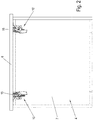
- a drawer 4 is movably held on two such rails 5, for which purpose a device 10 or 10 ′ is provided on each rail 5 for fixing the drawer 4 on the rail 5, as can be seen from the bottom view of FIG Figure 2 is recognizable.
- a first device 10 with lateral adjustment for fixing the drawer 4 and a second device 10 ′ without lateral adjustment for fixing the drawer are fixed to a rail 5 on a bottom 7 of the drawer 4.
- the device 10 is shown during assembly.
- the housing 15 can be fixed on the underside of the drawer 4 via fastening means 16, a receptacle 20 being provided for inserting a holding part 12.
- the holding part 12 is held on the rail 5 of the pull-out guide 3.
- the web-shaped holding part 12 can optionally be fixed to the rail 5 via an integrally formed tab 9, for example by welding, or can be fixed to the rail 5 via further components, or the holding part 12 is part of the rail profile of the rail 5.
- a device 11 for depth adjustment is provided, which has a non-rotatable threaded bolt 14 on which a knurled nut 13 is rotatably but axially immovable.
- the threaded bolt 14 can be moved in the longitudinal direction of the rail 5 and thus move a stop which specifies the maximum insertion depth of the holding part 12 in the receptacle 20.
- a stop which specifies the maximum insertion depth of the holding part 12 in the receptacle 20.
- such a device 11 for depth adjustment can also be dispensed with.
- the drawer 4 is placed on the two rails 5 of the two pull-out guides 3 and pushed into the closed position.
- a web-shaped holding part 12 is inserted into the receptacle 20 of the device 10 or 10 'on opposite sides and over one Fixed clamping mechanism, which secures the holding part 12 in a clamping and frictional manner against being pulled out.
- FIG 4 the mounted position of the drawer 4 is shown.
- the holding part 12 has been inserted into the receptacle 20 and secured there against being pulled out.
- the lateral joint pattern can now be adjusted via a device 18 for side adjustment.
- the device 18 for lateral adjustment comprises a knurled nut 19 which, by turning, causes the housing 15 to be moved laterally relative to the receptacle 20 in the horizontal direction in order to carry out a lateral adjustment.
- FIG 5 the device 10 is shown without the holding part 12.
- the device 10 comprises a slide 17, which serves to unlock the clamping mechanism.
- the drawer 4 can be dismantled again after assembly by actuating the slide 17.
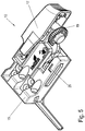
- the clamping mechanism comprises a clamping lever 25 which is rotatably mounted on a fastening part 23 about a bolt-shaped axis of rotation 24.
- the fastening part 23 is plate-shaped and forms a side wall 22 of the receptacle 20, which is arranged opposite the clamping lever 25.
- the holding part 12 is clamped between a contact surface 26 of the clamping lever 25 and the side wall 22 and secured against being pulled out.
- the axis of rotation 24, viewed in the direction of insertion of the holding part 12, is arranged in front of the contact surface 26, so that the holding part 12, when inserted into the receptacle 20, first passes through a plane perpendicular to the direction of insertion in which the axis of rotation 24 is arranged before the holding part 12 contacts the contact surface 26 touched.
- the clamping lever 25 is designed to be self-locking and, in the event of tensile forces on the holding part 12, the clamping lever 25 with the surface 26 is pressed even more strongly against the holding part 12.
- the clamping lever 25 is designed as a two-armed lever, the contact surface 26 being designed to clamp the holding part 12 in a clamping manner on one arm, and means for unlocking the clamping lever 25 engage on a second arm 27.
- the clamping lever 25 is angular and is biased into the clamping position by an integrally formed spring 30.
- the spring 30 is designed as a leaf spring and is supported on the housing 15.
- the unlocking means comprise a bolt 28 which is slidably formed in a wedge-shaped gap 29 between the arm 27 and the fastening part 23. If the bolt 28 is displaced towards the end of the arm 27, the wedge-shaped design of the gap 29 moves the arm 27 and the clamping lever 25 rotates such that the contact surface 26 is disengaged from the holding part 12. As a result, the holding part 12 can be easily pulled out after turning the clamping lever 25.
- the bolt 28 is guided along a side wall of the fastening part 23.
- the clamping lever 25 is made of a bent metal sheet which engages around a section of the plate-shaped fastening part 23 in a U-shape.
- the bottom of the U is formed on the contact surface 26, so that a linear contact surface 26 abuts the holding part 12.
- FIG 7 an exploded view of the device 10 with the housing 15 is shown.
- a slot-shaped receptacle 33 is provided on the housing 15, on which the fastening part 23 is held displaceably with the clamping lever 25.
- a head section on the axis of rotation 24 is guided in a groove-shaped guide 34.
- the fastening part 23 can be guided over further or different surfaces in the housing 15.
- the slide 17 is shown, which is designed as a cap-shaped part and holds the bolt 28 between two arms 31.
- the bolt 28 can be moved along the wedge-shaped gap 29 by moving the slide 17.
- the slider 17 is biased by a spring 32 into an initial position in which the bolt 28 does not unlock the clamping lever 25. Only by moving the slide 17 against the force of the spring 32 is the locking lever 25 unlocked.
- the device 18 for lateral adjustment is shown, in which a threaded bolt 40 engages in a threaded bore 41.
- a knurled nut 19 is fixed on the threaded bolt 40, an edge of the knurled nut engaging in a U-shaped receptacle 35 on the fastening part 23.
- the fastening part 23 can thus be displaced relative to the housing 15 in the longitudinal direction of the threaded bolt 40, that is to say in a plane parallel to the front panel 6 of the drawer 4 and on the other hand is guided via the bolt 28 to the fastening part 23.
- the plate-shaped fastening part 23 is slidably mounted within the receptacle 33 of the housing 15 and in turn supports the clamping lever 25 itself via the axis of rotation 24.
- the slider 17 encompasses the housing 15 in a U-shaped manner and is guided linearly to move the clamping lever 25 for one To pivot unlocking process.
- Figure 9 the device 10 is shown in an unlocked position, in which the slide 17 has been pushed onto the housing 15.
- the bolt 28 moves the clamping lever 25, so that the contact surface 26 moves slightly away from the opposite side wall 22, so that a holding part 12, which is arranged between the side wall 22 and the contact surface 26, can be pulled out of the receptacle 20.
- the movement of the contact surface 26 can be in a range between 0.02 to 4 mm, in particular 0.4 mm to 2 mm.
- the device 10 ' is shown, which is designed like the device 10, but without the device 18 for lateral adjustment. Insofar as the knurled nut 19 and the threaded bolt 40 are missing, the rest of the device 10 'can be constructed identically or mirror-symmetrically to the device 10.
- the fastening part 23 can be movably mounted in the housing 15, so that the device 10 'forms a loose bearing in the horizontal lateral direction, while a fixed bearing is provided on the opposite side, which positions the drawer 4 within the furniture body 2 in the horizontal lateral direction .
- both the clamping lever 25 and the fastening part 23 are made of metal, in particular a steel sheet. Particularly high holding forces can thereby be applied to the likewise metallic holding part 12.
- FIG 11 A further exemplary embodiment of a device 110 for fixing a movable furniture part is shown, on which a receptacle 120 for receiving the holding part 112 is formed.
- the device 110 comprises a plate-shaped fastening part 123, on which the clamping lever 125 is rotatably mounted about an axis of rotation 124.
- the clamping lever 25 can also be fastened differently or can be made in one piece with the fastening part 123. If the clamping lever is not rotatably mounted, the clamping lever can be bent to perform its function.
- the clamping lever 125 is made of a bent metal sheet which engages around a section of the plate-shaped fastening part 123 in a U-shape.
- a contact surface 126 is formed on the bottom of the U, which bears against the holding part 112 as a linear contact.
- the fixing of the holding part 112 can, as in the first exemplary embodiment ( Figures 3 and 4th ) respectively.
- a modified slide 127 is also provided on the fastening part 123, which serves to unlock the clamping lever 125.
- a holder 136 is provided on the slide 127 to receive a section 137 of a wire bracket, which is used to unlock the clamping lever 125.
- the wire bracket is arranged on the opposite side with a section 148 in a wedge-shaped gap 129 between the clamping lever 125 and the fastening part 123.
- FIG 12A the clamping lever 125 is shown in the locked position, but without the holding part 112.
- the slide 127 has spring elements 142 which are supported against a latching receptacle 143 on the clamping lever 125 and thus hold the slide 127 in its starting position.
- the slide 127 is moved against the force of the spring elements 142 along the elongated holes 138 until the in Figure 12B shown position is reached.
- the pull element of the means 128 for unlocking the clamping lever 125 is moved, which is moved along the gap 129 and has thereby pivoted the clamping lever 125 counterclockwise.
- the gap between the contact 126 of the clamping lever 125 and the opposite side wall 122 is enlarged, so that the holding part 112 can be pulled out of the receptacle 120 without being destroyed.
- the plate-shaped fastening part 123 is inserted into a receptacle 133 on the housing 115.
- a recess 121 is also formed on the housing 115 in the region of the receptacle 120.
- the fastening part 123 has a receptacle 135 for inserting an edge section of the knurled nut 119, so that the fastening part 123 can be displaced relative to the housing 115 for a lateral adjustment.
- a modified device 110 ' is shown, by means of which a web-shaped holding part 112 can be fixed by clamping.
- the device 110 ' comprises a housing 115', on which an outer plate 150 and an inner plate 152 are arranged.
- a slot-shaped receptacle 120 is recessed in the plates 150 and 152, in which a side wall 122 is arranged on one side and a clamping lever 125 is rotatably mounted about an axis of rotation 124 on the opposite side.
- the web-shaped holding part 112 can be frictionally fixed between a surface 126 on the clamping lever and the side wall 122.
- Elongated holes 153 are also formed on the plates 150 and 152, which serve to guide a pin which is connected to a slide 151.
- the slider 151 is biased into a starting position by a spring 154, the spring 154 being fixed on the one hand to the slider 151 and on the other hand to the plate 150.
- the clamping lever 125 comprises an actuating arm 157 which can cooperate with the slide 151.
- a receptacle 131 is further provided for inserting a spring 130, which is designed as a leaf spring and acts on the clamping lever 125 in order to pretension it in the locked position.
- a device 210 for fixing a movable furniture part is shown.
- a housing 215 is fixed to an underside and / or a front panel of a drawer 4 via fastening means, a receptacle 220 for inserting a holding part 212 being provided on the device 210.
- the holding part 212 can be fixed on a rail 5 of the pull-out guide 3.
- the web-shaped holding part 212 can optionally be integral trained tab 9 on the rail 5, or be fixed as at least one further component on the rail 5 or the holding part 12 is part of the rail profile of the rail 5.
- a device for depth adjustment can be provided to the insertion depth of the holding part 212 in the receptacle 220.
- such a device for depth adjustment can also be dispensed with.
- the web-shaped holding part 212 is inserted into the receptacle 220 of the device 210 and fixed via a clamping mechanism, which secures the holding part 212 in a clamping and frictional manner against being pulled out.
- a linearly movable web 228 is provided, which is connected to a slide 217, which is biased into a starting position via a spring 232.
- the spring 232 is supported on the one hand on the slide 217 and on the other hand on a stop 233 on the tab 209.
- the web-shaped holding part 212 is inserted into the receptacle 220 for mounting and secured there against being pulled out.
- a clamping mechanism is provided on the receptacle 220, which has a clamping lever 225 rotatably mounted about an axis of rotation 224.
- the clamping lever 225 has a contact surface 226 which can be frictionally applied against a side surface of the holding part 212.
- the holding part 212 is supported by a side wall 222 which is formed on a plate-shaped fastening part 223, on which the clamping lever 225 is also rotatably mounted.
- the clamp lever 225 has an integrally formed spring 230 that abuts a stop 227 to bias the clamp lever 225 into the locking position.
- the clamping lever 225 is made of a bent metal sheet which engages around a section of the plate-shaped fastening part 223 in a U-shape. At the bottom of the U, the contact surface 226 is formed, which rests as a linear contact surface 226 on the holding part 212.
- the holding web 228 can be pushed into the receptacle 220 via the slide 217 against the force of the spring 232, whereby the clamping lever 225 in Figure 16 is pressed counterclockwise and thus stands out from the holding part 212. In this position, the holding part 212 can then be pulled out of the receptacle 220 without being destroyed.
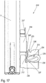
- FIG 17 A modified device 210 'for fixing a drawer to a rail 5 of a pull-out guide is shown, in which a housing has been hidden.
- a web-shaped holding part 212 is inserted into the receptacle 220 and frictionally fixed there by means of the clamping lever 225, the means for unlocking not being formed by a linearly displaceable slide 217 but by a pivotable lever 217 '.
- the lever 217 ' can be pivoted about the bearing pin 218', thereby moving the clamping lever 225 into an unlocked position.
- the lever 217 ' is connected to an unlocking element 228' which moves the clamping lever 225 accordingly.
- a device for side, height, and depth adjustment can be provided in devices 210 or 210 'in order to adapt the joint pattern.
- the device for side adjustment can have, for example, a knurled nut which engages with a rim in a receptacle 235 and, by rotating, causes a housing to be moved laterally relative to the receptacle 220 in the horizontal direction, as has already been described above.
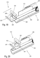
- FIG 19 A device 310 for fixing a movable furniture part is shown, in which a receptacle 320 is formed on a fastening part 323.
- the receptacle 320 is formed by a gap between two clamping levers 325 in the form of flaps which are pivotally mounted on the fastening part 323 via a bending edge 324.
- the clamping levers 325 are integrally formed with the fastening part 323, which is made of a bent steel sheet.
- a holding part 312 can be fixed to the receptacle 320, which is designed in the form of a strip and can likewise consist of a steel sheet.
- the holding part 312 is fixed on a movable running rail 305 of a pull-out guide 301, for example by welding.
- the pull-out guide 301 comprises a stationary guide rail 302 which can be fixed on a furniture body.
- An unlocking element 328 is provided for unlocking the clamping mechanism, by means of which the clamping levers 325 designed as flaps can easily move in the opening direction.
- the unlocking element 328 is pivotally mounted on the fastening part 323, as shown in FIGS Figures 22A and 22B is recognizable.
- the unlocking element 328 can, however, also be movably guided on a curve guide or in another way in order to act on the clamping lever 325.
- the device can be designed with further clamping mechanisms so that the movable furniture part can be pushed to the desired depth, height, and / or side and then fixed.
Landscapes
- Drawers Of Furniture (AREA)
Claims (20)
- Meuble (1) comprenant un tiroir (4), un guidage de déploiement (3) et un dispositif de fixation du tiroir (4) sur un rail déplaçable (5) du guidage de déploiement, le meuble (1) comprenant un corps de meuble (2) sur les parois latérales duquel est fixé le guidage de déploiement (3), le dispositif comprenant un mécanisme de serrage ayant un logement (20, 120, 220, 320) dans lequel peut être insérée une pièce de retenue en forme de barrette (12, 112, 212, 312), sur le logement (20, 120, 220, 320) étant prévu un levier de serrage à autoblocage (25, 125, 225, 325) au moyen duquel la pièce de retenue (12, 112, 212, 312) est bloquée par une liaison par friction pour empêcher son extraction, et des moyens de déverrouillage (28, 128, 228, 328) du levier de serrage (25, 125, 225, 325) étant prévus, pour permettre de libérer la liaison par une liaison par friction du levier de serrage (25, 125, 225, 325) de la pièce de retenue (12, 112, 212, 312).
- Meuble conforme à la revendication 1,
caractérisé en ce que
le levier de serrage (25, 125, 225, 325) est monté mobile en rotation autour d'un axe de rotation (24, 124, 224). - Meuble conforme à la revendication 1 ou 2,
caractérisé en ce que
le levier de serrage (25, 125, 225, 325) est rappelé dans la position verrouillée. - Meuble conforme à l'une des revendications précédentes,
caractérisé en ce que
pour permettre le déverrouillage du levier de serrage (25, 125, 225) il est prévu un coulisseau mobile linéairement (17). - Meuble conforme à l'une des revendications précédentes,
caractérisé en ce que
le levier de serrage (25, 125, 225, 325) est réalisé sous la forme d'un levier à deux bras et un premier bras s'applique par une surface de contact (26, 126, 226, 326) sur la pièce de retenue (12, 112, 212, 312) tandis que le second bras peut être déplacé par l'intermédiaire de moyens (28) permettant de déverrouiller le levier de serrage (25, 125, 225, 325). - Meuble conforme à l'une des revendications précédentes 2 à 5,
caractérisé en ce que
le levier de serrage (25, 125, 225, 325) s'applique sur la pièce de retenue (12, 112, 212, 312) par une surface de contact linéaire (26, 126, 226, 326) qui s'étend parallèlement à l'axe de rotation (24) du levier de serrage (25, 125, 225, 325). - Meuble conforme à l'une des revendications précédentes,
caractérisé en ce que
la pièce de retenue (12, 112, 212, 312) peut être fixée de manière continue sur le mécanisme de serrage. - Meuble conforme à l'une des revendications précédentes,
caractérisé en ce que
la surface du levier de serrage (23) s'appliquant sur la pièce de retenue (12, 112, 212, 312) ainsi que la pièce de retenue (12, 112, 212, 312) sont réalisées en métal. - Meuble conforme à l'une des revendications précédentes 2 à 8,
caractérisé en ce que
l'axe de rotation (24) du levier de serrage (25, 125, 225, 325) est situé dans la direction d'insertion à l'avant de la surface de contact (26, 126, 226, 326) du levier de serrage (25, 125, 225, 325) sur la pièce de retenue (12, 112, 212, 312). - Meuble conforme à l'une des revendications précédentes,
caractérisé en ce que
le logement (20, 120, 220, 320) est formé sur une pièce de fixation (23) sur laquelle le levier de serrage (25, 125, 225, 325) est monté mobile en rotation. - Meuble conforme à la revendication 10,
caractérisé en ce que
la pièce de fixation (23) est montée mobile en translation sur ou dans un boîtier (15). - Meuble conforme à la revendication 11,
caractérisé en ce que
la pièce de fixation (23) peut être déplacée par rapport au boîtier (15) par l'intermédiaire de moyens (19) de réglage latéral. - Meuble conforme à l'une des revendications précédentes,
caractérisé en ce que
le levier de serrage (325) comporte des éléments de serrage flexibles. - Meuble conforme à l'une des revendications précédentes,
caractérisé en ce qu'
il est prévu au moins un dispositif de réglage qui règle le tiroir (4) par rapport au guidage de déploiement (3) dans au moins une direction spatiale. - Meuble conforme à l'une des revendications précédentes,
caractérisé en ce qu'
il est prévu une pièce de fixation (23, 123, 223, 323) sur laquelle le levier de serrage (25, 125, 225, 325) est directement ou indirectement installé ou le levier de serrage (25, 125, 225, 325) est réalisé en une seule pièce avec la pièce de fixation (23, 123, 223, 323). - Meuble conforme à l'une des revendications précédentes,
caractérisé en ce qu'
il est prévu plusieurs mécanismes de serrage permettant d'orienter le tiroir (4) dans une position d'orientation. - Meuble conforme à la revendication 16,
caractérisé en ce qu'
une butée d'un dispositif de réglage limite la profondeur d'insertion du mécanisme de serrage. - Meuble conforme à l'une des revendications précédentes,
caractérisé en ce que
le tiroir (4) est maintenu mobile sur le corps de meuble (2) par l'intermédiaire de deux guidages de déploiement (3). - Procédé permettant d'orienter un élément de meuble mobile sur un composant (5) d'une ferrure (3) dans le corps de meuble d'un meuble conforme à l'une des revendications précédentes,
comprenant au moins un mécanisme de serrage comportant un logement de réception (20) d'au moins une pièce de retenue (12) et au moins un dispositif de réglage de l'élément de meuble mobile (4),
caractérisé en ce que
l'élément de meuble mobile est positionné sur la ferrure, l'élément de meuble mobile est introduit dans le corps de meuble jusqu'à une position d'insertion, fixé par l'intermédiaire d'un mécanisme de serrage qui bloque la pièce de retenue (12, 212) par une liaison par friction pour empêcher son extraction et le réglage est effectué de sorte que le mécanisme de serrage ne puisse pas être plus poussé sur la pièce de retenue. - Procédé conforme à la revendication 19,
caractérisé en ce que
la direction d'insertion sert à effectuer un alignement dans au moins une direction spatiale.
Applications Claiming Priority (2)
| Application Number | Priority Date | Filing Date | Title |
|---|---|---|---|
| DE102015106873.7A DE102015106873A1 (de) | 2015-05-04 | 2015-05-04 | Vorrichtung und Verfahren zum Festlegen eines bewegbaren Möbelteils |
| PCT/EP2016/059887 WO2016177730A1 (fr) | 2015-05-04 | 2016-05-03 | Dispositif et procédé pour immobiliser une pièce de meuble mobile |
Publications (2)
| Publication Number | Publication Date |
|---|---|
| EP3291706A1 EP3291706A1 (fr) | 2018-03-14 |
| EP3291706B1 true EP3291706B1 (fr) | 2020-04-22 |
Family
ID=55963333
Family Applications (1)
| Application Number | Title | Priority Date | Filing Date |
|---|---|---|---|
| EP16721771.0A Active EP3291706B1 (fr) | 2015-05-04 | 2016-05-03 | Meuble et procédé pour immobiliser une pièce de meuble mobile |
Country Status (6)
| Country | Link |
|---|---|
| US (1) | US10299587B2 (fr) |
| EP (1) | EP3291706B1 (fr) |
| CN (1) | CN107683098B (fr) |
| DE (1) | DE102015106873A1 (fr) |
| ES (1) | ES2803049T3 (fr) |
| WO (1) | WO2016177730A1 (fr) |
Families Citing this family (13)
| Publication number | Priority date | Publication date | Assignee | Title |
|---|---|---|---|---|
| DE102015106855A1 (de) * | 2015-05-04 | 2016-11-10 | Paul Hettich Gmbh & Co. Kg | Vorrichtung und Verfahren zum Festlegen eines Schubelementes |
| DE102015106856A1 (de) * | 2015-05-04 | 2016-11-10 | Paul Hettich Gmbh & Co. Kg | Vorrichtung und Verfahren zum Festlegen eines Schubelementes |
| DE102015106852A1 (de) * | 2015-05-04 | 2016-11-10 | Paul Hettich Gmbh & Co. Kg | Vorrichtung und Verfahren zum Festlegen eines Schubelementes |
| DE102015106854A1 (de) * | 2015-05-04 | 2016-11-10 | Paul Hettich Gmbh & Co. Kg | Vorrichtung und Verfahren zum Festlegen eines Schubelementes |
| DE102015106873A1 (de) * | 2015-05-04 | 2016-11-10 | Paul Hettich Gmbh & Co. Kg | Vorrichtung und Verfahren zum Festlegen eines bewegbaren Möbelteils |
| CN107822340B (zh) * | 2017-10-26 | 2019-06-25 | 浦江县恒川信息科技有限公司 | 一种多功能中药柜及其制作、安装和使用方法 |
| DE102018114712A1 (de) * | 2017-11-23 | 2019-05-23 | Paul Hettich Gmbh & Co. Kg | Vorrichtung zum Festlegen eines Schubelementes und Möbel |
| DE102018104398A1 (de) * | 2018-02-27 | 2019-08-29 | Paul Hettich Gmbh & Co. Kg | Möbel oder Haushaltsgerät und Verfahren zur Montage einer Funktionseinheit eines Schubelements in einem Möbel oder Haushaltsgerät |
| DE102018108647A1 (de) * | 2018-04-11 | 2019-10-17 | Paul Hettich Gmbh & Co. Kg | Auszugsführung und Schubkastenserie |
| DE102019113107A1 (de) * | 2019-05-17 | 2020-11-19 | Paul Hettich Gmbh & Co. Kg | Schubkasten und Verfahren zur Montage eines Schubkastens |
| DE102020100791A1 (de) | 2020-01-15 | 2021-07-15 | Paul Hettich Gmbh & Co. Kg | Verbindungsvorrichtung zum Befestigen eines bewegbaren Möbelteils an einer Auszugsführung |
| DE102020103955A1 (de) * | 2020-02-14 | 2021-08-19 | Paul Hettich Gmbh & Co. Kg | Befestigungsvorrichtung zur Fixierung eines Schubelementes |
| IT202000030218A1 (it) * | 2020-12-09 | 2022-06-09 | Salice Arturo Spa | Dispositivo di aggancio per cassetti |
Family Cites Families (55)
| Publication number | Priority date | Publication date | Assignee | Title |
|---|---|---|---|---|
| AT398516B (de) * | 1992-02-05 | 1994-12-27 | Fulterer Gmbh | Schubkastenauszug |
| EP0606564B1 (fr) * | 1993-01-12 | 1996-09-18 | Paul Hettich Gmbh & Co. | Dispositif de réglage de l'orientation de tiroirs et similaires |
| AT404220B (de) * | 1994-07-13 | 1998-09-25 | Alfit Ag | Vorrichtung zur befestigung einer auszugsführung |
| DE4432820B4 (de) * | 1994-09-15 | 2007-03-22 | MEPLA-WERKE LAUTENSCHLäGER GMBH & CO. KG | Beschlag zur Höhenverstellung von Schubladen |
| TW302275B (fr) | 1995-05-12 | 1997-04-11 | Ferrari Franco | |
| DE20107278U1 (de) | 2001-04-27 | 2001-08-02 | Paul Hettich Gmbh & Co., 32278 Kirchlengern | Vorrichtung zur Herstellung einer Rastverbindung |
| TWI249389B (en) * | 2002-06-19 | 2006-02-21 | Salice Arturo Spa | Device for adjusting the height of a drawer |
| DE20217545U1 (de) * | 2002-11-13 | 2003-01-23 | Arturo Salice S.P.A., Novedrate, Como | Scharnier |
| ATE526850T1 (de) * | 2003-05-13 | 2011-10-15 | Grass Gmbh | Frontalverriegelungsvorrichtung für das lösbare ineingriffbringen einer schublade in einem schubladenschieber |
| DE202004001791U1 (de) * | 2004-02-06 | 2004-05-06 | ACE Stoßdämpfer GmbH | Dämpfungsvorrichtung zum Abbremsen von beweglichen Massen, z.B. Möbelschubladen, Möbeltüren, Möbelklappen o.dgl. |
| DE202004015100U1 (de) * | 2004-09-29 | 2006-02-09 | Alfit Ag | Befestigungsanordnung für die lösbare Befestigung von Ausziehführungen an Schubladen |
| DE202006006065U1 (de) * | 2006-04-13 | 2007-08-23 | Alfit Ag | Unterflur-Führungsanordnung für Möbelteile, insbesondere im Korpus von Möbelstücken |
| AU2009228047A1 (en) * | 2008-03-28 | 2009-10-01 | Zonit Structured Solutions, Llc | Uniform equipment mounting system |
| TW200944157A (en) * | 2008-04-18 | 2009-11-01 | King Slide Works Co Ltd | Positioning device for a drawer with a drawer slide |
| AT506879B1 (de) * | 2008-06-10 | 2011-07-15 | Blum Gmbh Julius | Vorrichtung zum lösbaren kuppeln einer schublade mit einer schiene einer schubladenausziehführung |
| CN101711627B (zh) * | 2008-10-08 | 2011-09-21 | 世塑有限公司 | 上压式拆卸及结合结构 |
| US8328299B2 (en) * | 2009-04-27 | 2012-12-11 | Accuride International Inc. | Drawer slide and locking mechanism |
| DE202009013706U1 (de) * | 2009-11-10 | 2011-03-31 | Paul Hettich Gmbh & Co. Kg | Vorrichtung zur Koppelung eines Schubkastens mit einer Laufschiene einer Auszugsführung |
| AT508544B1 (de) | 2009-11-27 | 2011-02-15 | Blum Gmbh Julius | Kupplungsvorrichtung zum lösbaren verbinden einer schublade mit einer bewegbaren schiene |
| DE202009017319U1 (de) | 2009-12-21 | 2011-05-05 | Grass Gmbh | Möbel und Vorrichtung für ein Möbel |
| AT509414B1 (de) * | 2010-02-03 | 2013-04-15 | Blum Gmbh Julius | Kupplungsvorrichtung mit seitenverstellung für eine schublade |
| AT509366B1 (de) * | 2010-02-03 | 2015-08-15 | Blum Gmbh Julius | Schubladenbehälter |
| DE202010007765U1 (de) | 2010-06-09 | 2011-11-29 | Grass Gmbh | Rastvorrichtung für ein bewegliches Möbelteil und Vorrichtung zur Bewegungsführung |
| AT510774B1 (de) * | 2010-11-23 | 2014-12-15 | Blum Gmbh Julius | Befestigungsvorrichtung für wandteile |
| ITMI20102292A1 (it) * | 2010-12-15 | 2012-06-16 | Salice Arturo Spa | Dispositivo di aggancio di un cassetto ad una guida longitudinale |
| IT1403106B1 (it) * | 2010-12-15 | 2013-10-04 | Salice Arturo Spa | Dispositivo di aggancio di un cassetto ad una guida longitudinale |
| AT510905A1 (de) * | 2011-01-05 | 2012-07-15 | Blum Gmbh Julius | Kupplungsvorrichtung für schubladen |
| AT510714B1 (de) * | 2011-01-05 | 2012-06-15 | Blum Gmbh Julius | Kupplungsvorrichtung für schubladen |
| DE102011000724A1 (de) * | 2011-02-14 | 2012-08-16 | Paul Hettich Gmbh & Co. Kg | Vorrichtung zur Verriegelung relativ zueinander beweglicher Teile |
| DE202011004588U1 (de) * | 2011-03-30 | 2012-07-04 | Grass Gmbh | Führungseinrichtung zur Führung eines relativ zu einem Möbelkorpus bewegbaren Möbelauszugs |
| AT511294B1 (de) * | 2011-04-11 | 2013-06-15 | Blum Gmbh Julius | Schubladenausziehführung |
| DE102011052564A1 (de) * | 2011-05-17 | 2012-11-22 | Paul Hettich Gmbh & Co. Kg | Verschiebbares Möbelteil und Möbel |
| DE202011104673U1 (de) * | 2011-08-18 | 2012-11-20 | Grass Gmbh | Vorrichtung zur lösbaren Verbindung eines in einem Möbelkorpus über eine Führungseinheit beweglich geführten Möbelauszugs mit der Führungseinheit |
| ITMI20111628A1 (it) * | 2011-09-08 | 2013-03-09 | Salice Arturo Spa | Dispositivo e metodo per il centraggio laterale di un cassetto o simile su una guida di estrazione e dispositivo di aggancio provvisto dello stesso |
| AT512748B1 (de) * | 2012-04-13 | 2017-04-15 | Blum Gmbh Julius | Einstellvorrichtung zum Einstellen einer Lage einer Schublade |
| KR101406781B1 (ko) * | 2012-10-24 | 2014-06-17 | 박윤식 | 서랍용 슬라이드 탈착장치 |
| US8979223B2 (en) * | 2012-12-12 | 2015-03-17 | Nan Juen International Co., Ltd. | Adjustable coupling device for connection between sliding rail assembly and a sliding box |
| DE102013104829A1 (de) | 2013-05-10 | 2014-11-13 | Paul Hettich Gmbh & Co. Kg | Auszugsführung |
| DE102013104830A1 (de) * | 2013-05-10 | 2014-11-13 | Paul Hettich Gmbh & Co. Kg | Verbindungsvorrichtung für ein bewegbares Möbelteil |
| US9101213B2 (en) * | 2013-11-22 | 2015-08-11 | Hardware Resources, Inc. | Undermount drawer slide position adjustment apparatus and method of use |
| US9986829B2 (en) * | 2013-11-22 | 2018-06-05 | Hardware Resources, Inc. | Undermount drawer slide position adjustment apparatus and method of use |
| US10149539B2 (en) * | 2013-11-22 | 2018-12-11 | Hardware Resources, Inc. | Undermount drawer slide position adjustment apparatus and method of use |
| DE102014200550B4 (de) * | 2014-01-14 | 2015-07-30 | Kintec-Solution Gmbh | Schwenkgelenk und Möbelstück mit einem solchen |
| AT14476U1 (de) | 2014-02-13 | 2015-11-15 | Blum Gmbh Julius | Ausziehführung für ein bewegbares Möbelteil |
| DE102014104136A1 (de) | 2014-03-25 | 2015-10-01 | Paul Hettich Gmbh & Co. Kg | Auszugsführung für einen Schubkasten und Verfahren zur Befestigung eines Schubkastens an einer Auszugsführung |
| US8854769B1 (en) * | 2014-04-07 | 2014-10-07 | King Slide Works Co., Ltd. | Slide rail system and connecting device used for slide rail assembly |
| US9066587B1 (en) * | 2014-04-16 | 2015-06-30 | King Slide Works Co., Ltd. | Slide rail system and connecting device used for slide rail assembly |
| DE202014102893U1 (de) * | 2014-06-25 | 2015-10-05 | Grass Gmbh | Vorrichtung zur Anbringung einer Führungseinheit an einem Möbelteil |
| CN204181228U (zh) * | 2014-11-10 | 2015-03-04 | 广东泰明金属制品有限公司 | 抽屉滑轨的锁紧调节装置 |
| TWM495781U (zh) * | 2014-11-28 | 2015-02-21 | Sun Chain Trading Co Ltd | 隱藏式滑軌之前連接裝置 |
| DE102015106873A1 (de) * | 2015-05-04 | 2016-11-10 | Paul Hettich Gmbh & Co. Kg | Vorrichtung und Verfahren zum Festlegen eines bewegbaren Möbelteils |
| DE102015106852A1 (de) * | 2015-05-04 | 2016-11-10 | Paul Hettich Gmbh & Co. Kg | Vorrichtung und Verfahren zum Festlegen eines Schubelementes |
| DE102015106854A1 (de) * | 2015-05-04 | 2016-11-10 | Paul Hettich Gmbh & Co. Kg | Vorrichtung und Verfahren zum Festlegen eines Schubelementes |
| DE202015006933U1 (de) * | 2015-10-05 | 2017-01-09 | Grass Gmbh | Vorrichtung zur lösbaren Verbindung eines in einem Möbelkorpus eines Möbelteils über eine Führungseinheit beweglich geführten Möbelauszugs mit der Führungseinheit |
| AT518136B1 (de) * | 2016-01-13 | 2020-01-15 | Blum Gmbh Julius | Schubladenausziehführung |
-
2015
- 2015-05-04 DE DE102015106873.7A patent/DE102015106873A1/de not_active Ceased
-
2016
- 2016-05-03 US US15/569,151 patent/US10299587B2/en active Active
- 2016-05-03 WO PCT/EP2016/059887 patent/WO2016177730A1/fr not_active Ceased
- 2016-05-03 EP EP16721771.0A patent/EP3291706B1/fr active Active
- 2016-05-03 CN CN201680019356.7A patent/CN107683098B/zh active Active
- 2016-05-03 ES ES16721771T patent/ES2803049T3/es active Active
Non-Patent Citations (1)
| Title |
|---|
| None * |
Also Published As
| Publication number | Publication date |
|---|---|
| WO2016177730A1 (fr) | 2016-11-10 |
| CN107683098B (zh) | 2020-02-21 |
| CN107683098A (zh) | 2018-02-09 |
| DE102015106873A1 (de) | 2016-11-10 |
| EP3291706A1 (fr) | 2018-03-14 |
| US20180140095A1 (en) | 2018-05-24 |
| ES2803049T3 (es) | 2021-01-22 |
| US10299587B2 (en) | 2019-05-28 |
Similar Documents
| Publication | Publication Date | Title |
|---|---|---|
| EP3291704B1 (fr) | Meuble et procédé pour attacher un tiroir | |
| EP3291705B1 (fr) | Meuble avec tiroir et procédé pour fixer un tiroir | |
| WO2016177730A1 (fr) | Dispositif et procédé pour immobiliser une pièce de meuble mobile | |
| EP2083208B1 (fr) | Appareil, destiné à fixer un objet à un mur, ainsi qu'un élément mural et un élément de soutien qui sont adaptés à un tel appareil | |
| AT509416B1 (de) | Ausziehführung für eine schublade | |
| EP3291703B1 (fr) | Dispositif et procédé pour immobiliser un élément coulissant | |
| EP3291702B1 (fr) | Meuble et procédé pour fixer un tiroir | |
| DE102009003362B4 (de) | Vorrichtung zum Öffnen und/oder Schließen von Schubkästen und Verfahren zu ihrer Kalibrierung | |
| EP3713448B1 (fr) | Dispositif de fixation d'un tiroir et meuble | |
| EP2720577A1 (fr) | Guide de tiroir | |
| DE102016116178B4 (de) | Vorrichtung zur lösbaren Befestigung einer Frontblende an einem Schubkasten und Verfahren zur Montage oder Demontage einer Frontblende an einem Schubkasten | |
| WO2012110373A1 (fr) | Dispositif servant à verrouiller des pièces mobiles l'une par rapport à l'autre | |
| DE102011010828B4 (de) | Klemmvorrichtung zur lösbaren Befestigung eines Gerätegehäuses an einer Profilschiene | |
| EP3368734B1 (fr) | Dispositif de guidage de portes coulissantes et meuble de rangement | |
| EP4314449B1 (fr) | Élément d'accouplement, système de fermeture et meuble | |
| AT520767B1 (de) | Anordnung aus einem Auflagesteg für einen Schubladenboden und einer Haltevorrichtung | |
| EP3189749A1 (fr) | Guidage télescopique pour une partie de meuble mobile | |
| DE102017125609B3 (de) | Bandteil | |
| EP2540942B1 (fr) | Agencement de ferrure réglable | |
| EP3917360B1 (fr) | Dispositif pour fixer un tiroir et meuble | |
| EP2745734B1 (fr) | Meuble et dispositif de mise en place d'une face avant de meuble | |
| DE102005024529B4 (de) | Auszugführung und Auszugsperre für einen aus einem Korpus ausziehbaren Auszug | |
| EP3287042A1 (fr) | Glissière de tiroir pour parties de meuble | |
| DE202004001359U1 (de) | Führungsschiene für eine Steckkarte |
Legal Events
| Date | Code | Title | Description |
|---|---|---|---|
| STAA | Information on the status of an ep patent application or granted ep patent |
Free format text: STATUS: THE INTERNATIONAL PUBLICATION HAS BEEN MADE |
|
| PUAI | Public reference made under article 153(3) epc to a published international application that has entered the european phase |
Free format text: ORIGINAL CODE: 0009012 |
|
| STAA | Information on the status of an ep patent application or granted ep patent |
Free format text: STATUS: REQUEST FOR EXAMINATION WAS MADE |
|
| 17P | Request for examination filed |
Effective date: 20171109 |
|
| AK | Designated contracting states |
Kind code of ref document: A1 Designated state(s): AL AT BE BG CH CY CZ DE DK EE ES FI FR GB GR HR HU IE IS IT LI LT LU LV MC MK MT NL NO PL PT RO RS SE SI SK SM TR |
|
| AX | Request for extension of the european patent |
Extension state: BA ME |
|
| DAV | Request for validation of the european patent (deleted) | ||
| DAX | Request for extension of the european patent (deleted) | ||
| STAA | Information on the status of an ep patent application or granted ep patent |
Free format text: STATUS: EXAMINATION IS IN PROGRESS |
|
| 17Q | First examination report despatched |
Effective date: 20180814 |
|
| RIC1 | Information provided on ipc code assigned before grant |
Ipc: A47B 88/04 20181130AFI20161111BHEP |
|
| RIC1 | Information provided on ipc code assigned before grant |
Ipc: A47B 88/04 20060101AFI20161111BHEP |
|
| REG | Reference to a national code |
Ref country code: DE Ref legal event code: R079 Ref document number: 502016009656 Country of ref document: DE Free format text: PREVIOUS MAIN CLASS: A47B0088040000 Ipc: A47B0088427000 |
|
| RIC1 | Information provided on ipc code assigned before grant |
Ipc: A47B 88/427 20170101AFI20191007BHEP |
|
| GRAP | Despatch of communication of intention to grant a patent |
Free format text: ORIGINAL CODE: EPIDOSNIGR1 |
|
| STAA | Information on the status of an ep patent application or granted ep patent |
Free format text: STATUS: GRANT OF PATENT IS INTENDED |
|
| INTG | Intention to grant announced |
Effective date: 20191202 |
|
| GRAS | Grant fee paid |
Free format text: ORIGINAL CODE: EPIDOSNIGR3 |
|
| GRAA | (expected) grant |
Free format text: ORIGINAL CODE: 0009210 |
|
| STAA | Information on the status of an ep patent application or granted ep patent |
Free format text: STATUS: THE PATENT HAS BEEN GRANTED |
|
| AK | Designated contracting states |
Kind code of ref document: B1 Designated state(s): AL AT BE BG CH CY CZ DE DK EE ES FI FR GB GR HR HU IE IS IT LI LT LU LV MC MK MT NL NO PL PT RO RS SE SI SK SM TR |
|
| REG | Reference to a national code |
Ref country code: CH Ref legal event code: EP |
|
| REG | Reference to a national code |
Ref country code: IE Ref legal event code: FG4D Free format text: LANGUAGE OF EP DOCUMENT: GERMAN |
|
| REG | Reference to a national code |
Ref country code: DE Ref legal event code: R096 Ref document number: 502016009656 Country of ref document: DE |
|
| REG | Reference to a national code |
Ref country code: AT Ref legal event code: REF Ref document number: 1258928 Country of ref document: AT Kind code of ref document: T Effective date: 20200515 |
|
| REG | Reference to a national code |
Ref country code: LT Ref legal event code: MG4D |
|
| REG | Reference to a national code |
Ref country code: NL Ref legal event code: MP Effective date: 20200422 |
|
| PG25 | Lapsed in a contracting state [announced via postgrant information from national office to epo] |
Ref country code: IS Free format text: LAPSE BECAUSE OF FAILURE TO SUBMIT A TRANSLATION OF THE DESCRIPTION OR TO PAY THE FEE WITHIN THE PRESCRIBED TIME-LIMIT Effective date: 20200822 Ref country code: FI Free format text: LAPSE BECAUSE OF FAILURE TO SUBMIT A TRANSLATION OF THE DESCRIPTION OR TO PAY THE FEE WITHIN THE PRESCRIBED TIME-LIMIT Effective date: 20200422 Ref country code: LT Free format text: LAPSE BECAUSE OF FAILURE TO SUBMIT A TRANSLATION OF THE DESCRIPTION OR TO PAY THE FEE WITHIN THE PRESCRIBED TIME-LIMIT Effective date: 20200422 Ref country code: PT Free format text: LAPSE BECAUSE OF FAILURE TO SUBMIT A TRANSLATION OF THE DESCRIPTION OR TO PAY THE FEE WITHIN THE PRESCRIBED TIME-LIMIT Effective date: 20200824 Ref country code: NL Free format text: LAPSE BECAUSE OF FAILURE TO SUBMIT A TRANSLATION OF THE DESCRIPTION OR TO PAY THE FEE WITHIN THE PRESCRIBED TIME-LIMIT Effective date: 20200422 Ref country code: GR Free format text: LAPSE BECAUSE OF FAILURE TO SUBMIT A TRANSLATION OF THE DESCRIPTION OR TO PAY THE FEE WITHIN THE PRESCRIBED TIME-LIMIT Effective date: 20200723 Ref country code: SE Free format text: LAPSE BECAUSE OF FAILURE TO SUBMIT A TRANSLATION OF THE DESCRIPTION OR TO PAY THE FEE WITHIN THE PRESCRIBED TIME-LIMIT Effective date: 20200422 Ref country code: NO Free format text: LAPSE BECAUSE OF FAILURE TO SUBMIT A TRANSLATION OF THE DESCRIPTION OR TO PAY THE FEE WITHIN THE PRESCRIBED TIME-LIMIT Effective date: 20200722 |
|
| PG25 | Lapsed in a contracting state [announced via postgrant information from national office to epo] |
Ref country code: BG Free format text: LAPSE BECAUSE OF FAILURE TO SUBMIT A TRANSLATION OF THE DESCRIPTION OR TO PAY THE FEE WITHIN THE PRESCRIBED TIME-LIMIT Effective date: 20200722 Ref country code: RS Free format text: LAPSE BECAUSE OF FAILURE TO SUBMIT A TRANSLATION OF THE DESCRIPTION OR TO PAY THE FEE WITHIN THE PRESCRIBED TIME-LIMIT Effective date: 20200422 Ref country code: HR Free format text: LAPSE BECAUSE OF FAILURE TO SUBMIT A TRANSLATION OF THE DESCRIPTION OR TO PAY THE FEE WITHIN THE PRESCRIBED TIME-LIMIT Effective date: 20200422 Ref country code: LV Free format text: LAPSE BECAUSE OF FAILURE TO SUBMIT A TRANSLATION OF THE DESCRIPTION OR TO PAY THE FEE WITHIN THE PRESCRIBED TIME-LIMIT Effective date: 20200422 |
|
| PG25 | Lapsed in a contracting state [announced via postgrant information from national office to epo] |
Ref country code: AL Free format text: LAPSE BECAUSE OF FAILURE TO SUBMIT A TRANSLATION OF THE DESCRIPTION OR TO PAY THE FEE WITHIN THE PRESCRIBED TIME-LIMIT Effective date: 20200422 |
|
| REG | Reference to a national code |
Ref country code: ES Ref legal event code: FG2A Ref document number: 2803049 Country of ref document: ES Kind code of ref document: T3 Effective date: 20210122 |
|
| REG | Reference to a national code |
Ref country code: DE Ref legal event code: R097 Ref document number: 502016009656 Country of ref document: DE |
|
| PG25 | Lapsed in a contracting state [announced via postgrant information from national office to epo] |
Ref country code: EE Free format text: LAPSE BECAUSE OF FAILURE TO SUBMIT A TRANSLATION OF THE DESCRIPTION OR TO PAY THE FEE WITHIN THE PRESCRIBED TIME-LIMIT Effective date: 20200422 Ref country code: DK Free format text: LAPSE BECAUSE OF FAILURE TO SUBMIT A TRANSLATION OF THE DESCRIPTION OR TO PAY THE FEE WITHIN THE PRESCRIBED TIME-LIMIT Effective date: 20200422 Ref country code: SM Free format text: LAPSE BECAUSE OF FAILURE TO SUBMIT A TRANSLATION OF THE DESCRIPTION OR TO PAY THE FEE WITHIN THE PRESCRIBED TIME-LIMIT Effective date: 20200422 Ref country code: MC Free format text: LAPSE BECAUSE OF FAILURE TO SUBMIT A TRANSLATION OF THE DESCRIPTION OR TO PAY THE FEE WITHIN THE PRESCRIBED TIME-LIMIT Effective date: 20200422 Ref country code: CZ Free format text: LAPSE BECAUSE OF FAILURE TO SUBMIT A TRANSLATION OF THE DESCRIPTION OR TO PAY THE FEE WITHIN THE PRESCRIBED TIME-LIMIT Effective date: 20200422 Ref country code: RO Free format text: LAPSE BECAUSE OF FAILURE TO SUBMIT A TRANSLATION OF THE DESCRIPTION OR TO PAY THE FEE WITHIN THE PRESCRIBED TIME-LIMIT Effective date: 20200422 Ref country code: LI Free format text: LAPSE BECAUSE OF NON-PAYMENT OF DUE FEES Effective date: 20200531 Ref country code: CH Free format text: LAPSE BECAUSE OF NON-PAYMENT OF DUE FEES Effective date: 20200531 |
|
| PG25 | Lapsed in a contracting state [announced via postgrant information from national office to epo] |
Ref country code: SK Free format text: LAPSE BECAUSE OF FAILURE TO SUBMIT A TRANSLATION OF THE DESCRIPTION OR TO PAY THE FEE WITHIN THE PRESCRIBED TIME-LIMIT Effective date: 20200422 Ref country code: PL Free format text: LAPSE BECAUSE OF FAILURE TO SUBMIT A TRANSLATION OF THE DESCRIPTION OR TO PAY THE FEE WITHIN THE PRESCRIBED TIME-LIMIT Effective date: 20200422 |
|
| PLBE | No opposition filed within time limit |
Free format text: ORIGINAL CODE: 0009261 |
|
| STAA | Information on the status of an ep patent application or granted ep patent |
Free format text: STATUS: NO OPPOSITION FILED WITHIN TIME LIMIT |
|
| REG | Reference to a national code |
Ref country code: BE Ref legal event code: MM Effective date: 20200531 |
|
| 26N | No opposition filed |
Effective date: 20210125 |
|
| GBPC | Gb: european patent ceased through non-payment of renewal fee |
Effective date: 20200722 |
|
| PG25 | Lapsed in a contracting state [announced via postgrant information from national office to epo] |
Ref country code: LU Free format text: LAPSE BECAUSE OF NON-PAYMENT OF DUE FEES Effective date: 20200503 |
|
| PG25 | Lapsed in a contracting state [announced via postgrant information from national office to epo] |
Ref country code: GB Free format text: LAPSE BECAUSE OF NON-PAYMENT OF DUE FEES Effective date: 20200722 Ref country code: IE Free format text: LAPSE BECAUSE OF NON-PAYMENT OF DUE FEES Effective date: 20200503 |
|
| PG25 | Lapsed in a contracting state [announced via postgrant information from national office to epo] |
Ref country code: BE Free format text: LAPSE BECAUSE OF NON-PAYMENT OF DUE FEES Effective date: 20200531 Ref country code: SI Free format text: LAPSE BECAUSE OF FAILURE TO SUBMIT A TRANSLATION OF THE DESCRIPTION OR TO PAY THE FEE WITHIN THE PRESCRIBED TIME-LIMIT Effective date: 20200422 |
|
| PG25 | Lapsed in a contracting state [announced via postgrant information from national office to epo] |
Ref country code: MT Free format text: LAPSE BECAUSE OF FAILURE TO SUBMIT A TRANSLATION OF THE DESCRIPTION OR TO PAY THE FEE WITHIN THE PRESCRIBED TIME-LIMIT Effective date: 20200422 Ref country code: CY Free format text: LAPSE BECAUSE OF FAILURE TO SUBMIT A TRANSLATION OF THE DESCRIPTION OR TO PAY THE FEE WITHIN THE PRESCRIBED TIME-LIMIT Effective date: 20200422 |
|
| PG25 | Lapsed in a contracting state [announced via postgrant information from national office to epo] |
Ref country code: MK Free format text: LAPSE BECAUSE OF FAILURE TO SUBMIT A TRANSLATION OF THE DESCRIPTION OR TO PAY THE FEE WITHIN THE PRESCRIBED TIME-LIMIT Effective date: 20200422 |
|
| P01 | Opt-out of the competence of the unified patent court (upc) registered |
Effective date: 20230429 |
|
| PGFP | Annual fee paid to national office [announced via postgrant information from national office to epo] |
Ref country code: ES Payment date: 20240614 Year of fee payment: 9 |
|
| PGFP | Annual fee paid to national office [announced via postgrant information from national office to epo] |
Ref country code: FR Payment date: 20240516 Year of fee payment: 9 |
|
| PGFP | Annual fee paid to national office [announced via postgrant information from national office to epo] |
Ref country code: DE Payment date: 20250519 Year of fee payment: 10 |
|
| PGFP | Annual fee paid to national office [announced via postgrant information from national office to epo] |
Ref country code: IT Payment date: 20250530 Year of fee payment: 10 |
|
| PGFP | Annual fee paid to national office [announced via postgrant information from national office to epo] |
Ref country code: AT Payment date: 20250519 Year of fee payment: 10 |
|
| PGFP | Annual fee paid to national office [announced via postgrant information from national office to epo] |
Ref country code: TR Payment date: 20250425 Year of fee payment: 10 |
|
| PG25 | Lapsed in a contracting state [announced via postgrant information from national office to epo] |
Ref country code: FR Free format text: LAPSE BECAUSE OF NON-PAYMENT OF DUE FEES Effective date: 20250531 |