EP2083263A2 - Capteur de NOx et son procédé de fabrication - Google Patents
Capteur de NOx et son procédé de fabrication Download PDFInfo
- Publication number
- EP2083263A2 EP2083263A2 EP09000735A EP09000735A EP2083263A2 EP 2083263 A2 EP2083263 A2 EP 2083263A2 EP 09000735 A EP09000735 A EP 09000735A EP 09000735 A EP09000735 A EP 09000735A EP 2083263 A2 EP2083263 A2 EP 2083263A2
- Authority
- EP
- European Patent Office
- Prior art keywords
- measurement
- measurement chamber
- nox
- gas under
- pumping
- Prior art date
- Legal status (The legal status is an assumption and is not a legal conclusion. Google has not performed a legal analysis and makes no representation as to the accuracy of the status listed.)
- Withdrawn
Links
- 238000004519 manufacturing process Methods 0.000 title claims abstract description 9
- 238000005259 measurement Methods 0.000 claims abstract description 140
- 239000007789 gas Substances 0.000 claims abstract description 100
- 238000005086 pumping Methods 0.000 claims abstract description 84
- 239000001301 oxygen Substances 0.000 claims abstract description 45
- 229910052760 oxygen Inorganic materials 0.000 claims abstract description 45
- QVGXLLKOCUKJST-UHFFFAOYSA-N atomic oxygen Chemical compound [O] QVGXLLKOCUKJST-UHFFFAOYSA-N 0.000 claims abstract description 40
- 238000001514 detection method Methods 0.000 claims abstract description 40
- 230000001052 transient effect Effects 0.000 claims abstract description 21
- 230000009471 action Effects 0.000 claims abstract description 16
- 239000007784 solid electrolyte Substances 0.000 claims description 37
- 230000032683 aging Effects 0.000 claims description 31
- 239000000463 material Substances 0.000 claims description 12
- 238000000034 method Methods 0.000 abstract description 7
- MWUXSHHQAYIFBG-UHFFFAOYSA-N nitrogen oxide Inorganic materials O=[N] MWUXSHHQAYIFBG-UHFFFAOYSA-N 0.000 description 185
- 238000012360 testing method Methods 0.000 description 37
- 229910052751 metal Inorganic materials 0.000 description 14
- 239000002184 metal Substances 0.000 description 14
- 230000008859 change Effects 0.000 description 12
- 239000000919 ceramic Substances 0.000 description 9
- 238000009792 diffusion process Methods 0.000 description 9
- 230000000694 effects Effects 0.000 description 6
- 238000002485 combustion reaction Methods 0.000 description 5
- 230000008569 process Effects 0.000 description 5
- 238000004891 communication Methods 0.000 description 4
- BASFCYQUMIYNBI-UHFFFAOYSA-N platinum Chemical compound [Pt] BASFCYQUMIYNBI-UHFFFAOYSA-N 0.000 description 4
- 239000000454 talc Substances 0.000 description 4
- 229910052623 talc Inorganic materials 0.000 description 4
- PNEYBMLMFCGWSK-UHFFFAOYSA-N aluminium oxide Inorganic materials [O-2].[O-2].[O-2].[Al+3].[Al+3] PNEYBMLMFCGWSK-UHFFFAOYSA-N 0.000 description 3
- 239000004568 cement Substances 0.000 description 3
- 230000006866 deterioration Effects 0.000 description 3
- 238000010438 heat treatment Methods 0.000 description 3
- 238000003780 insertion Methods 0.000 description 3
- 230000037431 insertion Effects 0.000 description 3
- 230000004044 response Effects 0.000 description 3
- MCMNRKCIXSYSNV-UHFFFAOYSA-N Zirconium dioxide Chemical compound O=[Zr]=O MCMNRKCIXSYSNV-UHFFFAOYSA-N 0.000 description 2
- 239000000567 combustion gas Substances 0.000 description 2
- 230000000052 comparative effect Effects 0.000 description 2
- WABPQHHGFIMREM-UHFFFAOYSA-N lead(0) Chemical compound [Pb] WABPQHHGFIMREM-UHFFFAOYSA-N 0.000 description 2
- 229910052697 platinum Inorganic materials 0.000 description 2
- 239000011148 porous material Substances 0.000 description 2
- 230000001012 protector Effects 0.000 description 2
- 230000003213 activating effect Effects 0.000 description 1
- 230000004913 activation Effects 0.000 description 1
- 230000033228 biological regulation Effects 0.000 description 1
- 229910002091 carbon monoxide Inorganic materials 0.000 description 1
- 238000006555 catalytic reaction Methods 0.000 description 1
- 239000004020 conductor Substances 0.000 description 1
- 238000000354 decomposition reaction Methods 0.000 description 1
- 239000000446 fuel Substances 0.000 description 1
- 238000003475 lamination Methods 0.000 description 1
- 239000007769 metal material Substances 0.000 description 1
- 238000012986 modification Methods 0.000 description 1
- 230000004048 modification Effects 0.000 description 1
- 238000005192 partition Methods 0.000 description 1
- 239000000843 powder Substances 0.000 description 1
- 230000001105 regulatory effect Effects 0.000 description 1
- 238000005245 sintering Methods 0.000 description 1
- 229910001220 stainless steel Inorganic materials 0.000 description 1
- 239000010935 stainless steel Substances 0.000 description 1
- 238000003466 welding Methods 0.000 description 1
Images

Classifications
-
- G—PHYSICS
- G01—MEASURING; TESTING
- G01N—INVESTIGATING OR ANALYSING MATERIALS BY DETERMINING THEIR CHEMICAL OR PHYSICAL PROPERTIES
- G01N33/00—Investigating or analysing materials by specific methods not covered by groups G01N1/00 - G01N31/00
- G01N33/0004—Gaseous mixtures, e.g. polluted air
- G01N33/0009—General constructional details of gas analysers, e.g. portable test equipment
- G01N33/0027—General constructional details of gas analysers, e.g. portable test equipment concerning the detector
- G01N33/0036—General constructional details of gas analysers, e.g. portable test equipment concerning the detector specially adapted to detect a particular component
- G01N33/0037—NOx
-
- G—PHYSICS
- G01—MEASURING; TESTING
- G01N—INVESTIGATING OR ANALYSING MATERIALS BY DETERMINING THEIR CHEMICAL OR PHYSICAL PROPERTIES
- G01N27/00—Investigating or analysing materials by the use of electric, electrochemical, or magnetic means
- G01N27/26—Investigating or analysing materials by the use of electric, electrochemical, or magnetic means by investigating electrochemical variables; by using electrolysis or electrophoresis
- G01N27/403—Cells and electrode assemblies
- G01N27/406—Cells and probes with solid electrolytes
- G01N27/407—Cells and probes with solid electrolytes for investigating or analysing gases
- G01N27/4075—Composition or fabrication of the electrodes and coatings thereon, e.g. catalysts
-
- G—PHYSICS
- G01—MEASURING; TESTING
- G01N—INVESTIGATING OR ANALYSING MATERIALS BY DETERMINING THEIR CHEMICAL OR PHYSICAL PROPERTIES
- G01N27/00—Investigating or analysing materials by the use of electric, electrochemical, or magnetic means
- G01N27/26—Investigating or analysing materials by the use of electric, electrochemical, or magnetic means by investigating electrochemical variables; by using electrolysis or electrophoresis
- G01N27/403—Cells and electrode assemblies
- G01N27/406—Cells and probes with solid electrolytes
- G01N27/407—Cells and probes with solid electrolytes for investigating or analysing gases
- G01N27/4073—Composition or fabrication of the solid electrolyte
- G01N27/4074—Composition or fabrication of the solid electrolyte for detection of gases other than oxygen
-
- G—PHYSICS
- G01—MEASURING; TESTING
- G01N—INVESTIGATING OR ANALYSING MATERIALS BY DETERMINING THEIR CHEMICAL OR PHYSICAL PROPERTIES
- G01N27/00—Investigating or analysing materials by the use of electric, electrochemical, or magnetic means
- G01N27/26—Investigating or analysing materials by the use of electric, electrochemical, or magnetic means by investigating electrochemical variables; by using electrolysis or electrophoresis
- G01N27/416—Systems
- G01N27/417—Systems using cells, i.e. more than one cell and probes with solid electrolytes
-
- Y—GENERAL TAGGING OF NEW TECHNOLOGICAL DEVELOPMENTS; GENERAL TAGGING OF CROSS-SECTIONAL TECHNOLOGIES SPANNING OVER SEVERAL SECTIONS OF THE IPC; TECHNICAL SUBJECTS COVERED BY FORMER USPC CROSS-REFERENCE ART COLLECTIONS [XRACs] AND DIGESTS
- Y02—TECHNOLOGIES OR APPLICATIONS FOR MITIGATION OR ADAPTATION AGAINST CLIMATE CHANGE
- Y02A—TECHNOLOGIES FOR ADAPTATION TO CLIMATE CHANGE
- Y02A50/00—TECHNOLOGIES FOR ADAPTATION TO CLIMATE CHANGE in human health protection, e.g. against extreme weather
- Y02A50/20—Air quality improvement or preservation, e.g. vehicle emission control or emission reduction by using catalytic converters
Definitions
- FIG 2 is a sectional view of a sensor element of the NOx sensor according to one embodiment of the present invention.
- FIG. 3 is a graph showing a transient peak (offset) in the detection value of a commercially available conventional NOx sensor in the case where the moisture content of gas under measurement changes from 2 vol% to 8 vol%.
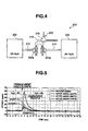
- FIG. 4 is a schematic view of an offset measurement piping system for the NOx sensor according to one embodiment of the present invention.
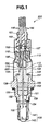
- a NOx sensor 200 for an automotive internal combustion engine includes a cylindrical metal shell 138, a plate-shaped sensor element 100, a cylindrical ceramic sleeve 106, an annular ceramic holder 151, talc rings 153 and 156 (as packed powder layers), a swage ring 157, a cylindrical metal holder 158, front and rear outer covers 135 and 144, a grommet 150, a cylindrical insulating contact member 166, six connection terminals 110, six lead wires 146 and a retaining member 169. It is noted that only two of the six connection terminals 110 and three of the six lead wires 146 are shown in FIG. 1 for ease of illustration.
- the metal holder 158 is fitted on the ceramic holder 151 and the talc ring 153 and seated on the stepped portion 152 of the metal shell 138 so as to hermetically retain the sensor element 100 together with the ceramic holder 151 and the talc ring 153.
- the rear outer cover 144 is attached to the rear end of the metal shell 138 and accommodates therein the protruding rear end portion of the sensor element 100.
- the grommet 150 is formed with a lead wire insertion hole 161 and fitted in a rear opening of the outer cover 144.
- the lead wires 146 are inserted through the lead wire insertion hole 161 of the grommet 150 and electrically connected to the terminal areas 220 and 221 of the rear end portion of the sensor element 100 via the connection terminals 110.
- the porous electrodes 35 and 36 are located on a side of the third solid electrolyte layer 24 facing the second solid electrolyte layer 23 at positions inside and outside the second measurement chamber 42 (i.e. at positions inside the second measurement chamber 42 and the reference oxygen chamber 63). As the solid electrolyte layer 24 allows oxygen ion conduction therethrough from the second measurement chamber 42 to the reference oxygen chamber 63 by the application of a voltage between the porous electrodes 35 and 36, the solid electrolyte layer 24 and the porous electrodes 35 and 36 function together as a second pumping cell that effects an oxygen pumping action against the second measurement chamber 42.
- the porous electrodes 35 and 36 are hereinafter referred to as "working electrode” and "counter electrode", respectively, for purposes of illustration.
- the above-structured NOx sensor 200 operates as follows.
- the second pumping cell then exerts its oxygen pumping action to pump the resulting O 2 from the second measurement chamber 142 into the reference oxygen chamber 63 and produce a second pumping cell current Ip2 therethrough as the result of pumping of the O 2 dissociated from the NOx in the gas under measurement.
- the NOx concentration of the gas under measurement can be determined based on the second pumping cell current Ip2.
- the NOx sensor 200 calculates a NOx concentration value (more specifically, a NO concentration value) from the second pumping cell current Ip2.
- a sensor control unit is provided with a microcomputer and connected with the sensor element 100 so as to convert the second pumping cell current Ip2 to a voltage, calculate the NOx concentration detection value from the voltage and output the NOx concentration detection value to an engine control unit for engine feedback control.
- the NOx concentration detection value can be calculated by the microcomputer according to the process disclosed in Japanese Laid-Open Patent Publication No- 11-304758 , Japanese Laid-Open Patent Publication No. 10-142194 and U.S. Patent No. 6214207 , which are hereby incorporated by reference. A detailed explanation of the NOx concentration calculation process will be thus omitted therefrom.
- the detection value (offset value) of a commercially available conventional NOx sensor for use in a diesel vehicle reaches a large transient peak value of 60 ppm due to a transient peak in pumping cell current as shown in FIG. 3 when the moisture content of gas under measurement changes from 2 vol% to 8 vol%. It takes several ten seconds from the change of the gas moisture content from 2 vol% to 8 vol% until when the detection value converges to its original, reference value (0 ppm). In this way, the NOx concentration detection accuracy of the conventional NOx sensor becomes deteriorated when the moisture content of the gas under measurement changes suddenly e.g. during driving.
- the NOx sensor 200 is so configured as to, when the moisture content of the gas under measurement changes from 2 vol % to 8 vol%, allow a variation of the NOx concentration detection value in such a manner that the NOx concentration detection value reaches a transient peak value of 20 ppm or smaller and converges to ⁇ 5 ppm of a reference value within 5 seconds of the time of change of the gas moisture content in the present embodiment.
- the reference value is defined as the original value of the second pumping cell current Ip2 before the change of the gas moisture content, i.e., the value of the second pumping cell Ip2 in a steady state where there is no change of gas moisture content.
- the NOx concentration detection value converges to ⁇ 10 ppm of the reference value within 3 seconds of the change of the gas moisture content. In this case, it is possible to prevent the detection accuracy deterioration of the NOx sensor 200 more effectively as the NOx concentration detection value converges more quickly.
- the above-specified transient peak characteristics of the NOx sensor 200 can be obtained easily and efficiently by subjecting the sensor element 100, notably the second pumping cell working electrode 35, to aging in a rich atmosphere of substantially constant moisture content through the application of a voltage between the second pumping cell working and counter electrodes 35 and 36 while heating the sensor element 100 (second pumping cell working electrode 35) to a given temperature range.
- the variation of the NOx concentration detection value can be limited by the aging treatment but is estimated that the surface of the second pumping cell working electrode 35 becomes porous through the aging treatment, which contributes to a decrease in the transient peak magnitude of the second pumping cell current Ip2 in response to the gas moisture change.
- the rich atmosphere of the aging treatment are an atmosphere of gas containing several vol% H 2 , more than 0 to 5 vol% or less H 2 O (moisture) and the balance being N 2 and an atmosphere of gas containing 1 vol% CO, 10 vol% CO 2 , more than 0 to 5 vol% or less H 2 O (moisture) and the balance being N 2 .
- the temperature of the second pumping cell during the aging treatment is set to e.g. 550 to 700°C.
- the voltage applied between the working and counter electrodes 35 and 36 during the aging treatment is set to e.g. over 0 to 1.8 V or lower.
- the time of the aging treatment is set to e.g. about 60 seconds.
- the voltage applied between the working and counter electrodes 35 and 36 during the aging treatment is an AC voltage varying between two discrete amplitudes (e.g. between the ON-voltage level of 0 to 1.8 V and the OFF-voltage level of 0 V) at given periodicity. It is particularly preferable to perform the aging treatment under the conditions that: the AC voltage between the working and counter electrodes 35 and 36 ranges from 1.0 to 1.8 V; the moisture content of the aging atmosphere ranges from 0.1 to 1 vol.%; and the temperature of the second pumping cell ranges from 600 to 700°C.
- the aging treatment can be performed on the sensor element 100 before the process of assembling the sensor element 100 into the NOx sensor 200 or after the process of assembling the sensor element 100 into the NOx sensor 200 (in finished or semi-finished form). Further, the aging treatment can be performed using the built-in heater 29 of the sensor element 100 or any other external heater.
- additional aging treatment may be performed by driving the NOx sensor 200 (sensor element 100) in a normal manner in an air atmosphere for a predetermined time period.
- the application of the NOx sensor 200 is not limited to the above.
- the NOx sensor 200 can be used not only to detect the NOx concentration of exhaust gas of the automotive internal combustion engine, but also to detect the NOx concentration of combustion gas of the automotive internal combustion engine or any other combustor such as boiler.
- Test samples of the NOx sensor 200 were produced and subjected to aging. The aging was performed on each test sample by heating the second pumping cell in a rich atmosphere containing 3 vol% H 2 , 0.5 vol% H 2 O and the balance being N 2 with the application of an AC voltage of 0V/1.6V between the second pumping cell working and counter electrodes 35 and 36. In Examples 1 to 3, the aging temperature was set to different levels ranging from 630 to 700°C. A test sample of NOx sensor (as Comparative Example) was produced in the same manner as above, except that the test sample was not subjected to aging.
- the offset measurement system 300 had a gas generation unit 302 capable of generating test gas A, a gas generation unit 304 capable of generating test gas B different in moisture content from the test gas A, gas valves 302a and 304a connected to the gas generation units 302 and 304 via gas pipes 312 and 314 to supply therethrough the test gas A and test gas B, respectively, and an integrated gas pipe 316 connected to the gas valves 302a and 304a and formed with a branch portion 318 to mount thereon the test sample and subject the test sample to the test gas A, B.
- Pure N 2 with a moisture content of 2 vol% was used as the test gas A and pure N 2 with a moisture content of 8 vol% was used as the test gas B.
- the O 2 content, CO 2 content, NO concentration of the test gas A, B were controlled to 0 vol%, 0 vol% and 0 ppm, respectively.
- the temperature of the test gas A, B was set to room temperature.
- the output (second pumping cell current Ip2) of the test sample was converted into a NOx concentration detection value (offset value) by the microcomputer of the sensor control unit.
- the offset value of the test sample in a steady state where there was no change in gas moisture content was set to 0 ppm.
- the test gas A was first supplied to the test sample at a rate of 4 m/s by opening the gas valve 302a and closing the gas valve 304a. Under the condition that the test sample was subjected to the test gas A, the offset value of the test sample was measured in real time.
- the test gas B was supplied to the test sample at a rate of 4 m/s by closing the gas valve 302a and opening the gas valve 304a.
- the inside of the gas pipe 316 was replaced from the test gas A to the test gas B during about 1 second.
- the offset value of the test sample was then measured in real time under the condition that the test sample was subjected to the test gas B. The measurement results are indicated in FIG 5 .
- Example 1 where the aging was performed at 700°C, the offset value of the test sample reached a peak value of 20 ppm or smaller.
- Example 2 where the aging was performed at 660°C, the offset value of the test sample reached a peak value of slightly over 10 ppm.
- Example 3 where the aging was performed at 630°C, the offset value of the test sample reached a lowest peak value of less than 10 ppm or less. Further, the offset value of the test sample converged to ⁇ 10 ppm within 3 seconds and to ⁇ 5 ppm within 5 seconds in each of Examples 1 to 3.
- Comparative Example where no aging was performed, by contrast, the offset value reached a transient peak value of much higher than 20 ppm.
- the configuration of the sensor element 100 is not limited to the above.
- the sensor element 100 may have a two-cell configuration with two solid electrolyte layers as discussed in Japanese Laid-Open Patent Publication No. 9-288085 ( FIG. 2 ) although the sensor element 100 has a three-cell configuration with three solid electrolyte layers 22, 23 and 24 in the above embodiment.
- the heater 29 was bonded to the side of the first solid electrolyte layer 22 by the cement 25 in the above embodiment, the heater 29 may be integrally formed on the side of the third solid electrolyte layer 24 by simultaneous sintering without using the cement 25.
Landscapes
- Chemical & Material Sciences (AREA)
- Health & Medical Sciences (AREA)
- Life Sciences & Earth Sciences (AREA)
- Analytical Chemistry (AREA)
- General Health & Medical Sciences (AREA)
- Pathology (AREA)
- Immunology (AREA)
- Physics & Mathematics (AREA)
- Engineering & Computer Science (AREA)
- Biochemistry (AREA)
- General Physics & Mathematics (AREA)
- Combustion & Propulsion (AREA)
- Medicinal Chemistry (AREA)
- Food Science & Technology (AREA)
- Molecular Biology (AREA)
- Chemical Kinetics & Catalysis (AREA)
- Electrochemistry (AREA)
- Measuring Oxygen Concentration In Cells (AREA)
Applications Claiming Priority (1)
| Application Number | Priority Date | Filing Date | Title |
|---|---|---|---|
| JP2008013227 | 2008-01-24 |
Publications (2)
| Publication Number | Publication Date |
|---|---|
| EP2083263A2 true EP2083263A2 (fr) | 2009-07-29 |
| EP2083263A3 EP2083263A3 (fr) | 2015-09-02 |
Family
ID=40548751
Family Applications (1)
| Application Number | Title | Priority Date | Filing Date |
|---|---|---|---|
| EP09000735.2A Withdrawn EP2083263A3 (fr) | 2008-01-24 | 2009-01-20 | Capteur de NOx et son procédé de fabrication |
Country Status (3)
| Country | Link |
|---|---|
| US (1) | US8512536B2 (fr) |
| EP (1) | EP2083263A3 (fr) |
| JP (2) | JP4981075B2 (fr) |
Cited By (3)
| Publication number | Priority date | Publication date | Assignee | Title |
|---|---|---|---|---|
| WO2012069241A1 (fr) * | 2010-11-24 | 2012-05-31 | Robert Bosch Gmbh | Sonde lambda pour la détermination d'une teneur en oxygène dans un gaz d'échappement et procédé pour la transmission d'un signal entre une sonde lambda et une interface électrique |
| EP2645093A3 (fr) * | 2012-03-29 | 2016-02-24 | NGK Insulators, Ltd. | Procédé de fabrication d'un élément capteur de gaz, du contrôle des caractéristiques électriques de l'élément de capteur de gaz, et de prétraitement de ce élément de capteur de gaz |
| EP2333535B1 (fr) * | 2009-12-14 | 2018-07-18 | NGK Insulators, Ltd. | Procédé de fabrication d'un élément capteur pour capteur de gaz |
Families Citing this family (7)
| Publication number | Priority date | Publication date | Assignee | Title |
|---|---|---|---|---|
| JP5204284B2 (ja) * | 2010-11-12 | 2013-06-05 | 日本特殊陶業株式会社 | ガスセンサ |
| JP5728426B2 (ja) * | 2012-04-19 | 2015-06-03 | 日本特殊陶業株式会社 | マルチガスセンサの製造方法 |
| US11054382B2 (en) | 2018-03-07 | 2021-07-06 | Ngk Spark Plug Co., Ltd. | Sensor and method of manufacturing sensor |
| JP7111608B2 (ja) * | 2018-03-07 | 2022-08-02 | 日本特殊陶業株式会社 | センサ及びセンサの製造方法 |
| JP7237866B2 (ja) * | 2019-04-08 | 2023-03-13 | 日本特殊陶業株式会社 | NOxセンサ素子及びNOxセンサ |
| US11549925B2 (en) | 2019-04-08 | 2023-01-10 | Ngk Spark Plug Co., Ltd. | NOx sensor element and NOx sensor |
| WO2024116510A1 (fr) * | 2022-11-28 | 2024-06-06 | 日本碍子株式会社 | Capteur de gaz, procédé de détermination de valeur cible de tension de réglage pour la commande d'élément de capteur, procédé de fabrication d'élément de capteur et procédé de fabrication de capteur de gaz |
Citations (7)
| Publication number | Priority date | Publication date | Assignee | Title |
|---|---|---|---|---|
| JPH0518938A (ja) | 1991-07-13 | 1993-01-26 | Ngk Spark Plug Co Ltd | 電気化学素子の処理方法 |
| JPH09288085A (ja) | 1996-02-23 | 1997-11-04 | Ngk Insulators Ltd | 酸化物センサ |
| JPH10142194A (ja) | 1996-11-08 | 1998-05-29 | Ngk Spark Plug Co Ltd | 酸素濃度・窒素酸化物濃度測定方法及び装置 |
| JPH11304758A (ja) | 1998-02-20 | 1999-11-05 | Ngk Spark Plug Co Ltd | ガスセンサ用制御回路ユニット及びそれを用いたガスセンサシステム |
| US6453724B1 (en) * | 1998-09-29 | 2002-09-24 | Denso Corporation | Gas concentration sensing apparatus |
| JP2004294079A (ja) | 2003-03-25 | 2004-10-21 | Ngk Spark Plug Co Ltd | ガスセンサの製造方法 |
| JP2008013227A (ja) | 2006-07-07 | 2008-01-24 | Ishida Co Ltd | 搬送装置およびこれを備えた箱詰め装置 |
Family Cites Families (9)
| Publication number | Priority date | Publication date | Assignee | Title |
|---|---|---|---|---|
| JPH0690178B2 (ja) * | 1986-07-01 | 1994-11-14 | 日本特殊陶業株式会社 | 空燃比検出素子及びその製造方法 |
| JP3623870B2 (ja) * | 1995-12-28 | 2005-02-23 | 日本特殊陶業株式会社 | 空燃比検出素子及びその製造方法、並びに空燃比検出素子の安定化方法 |
| KR100319947B1 (ko) * | 1998-04-06 | 2002-01-09 | 마츠시타 덴끼 산교 가부시키가이샤 | 탄화수소 센서 |
| JP2002048758A (ja) * | 2000-07-31 | 2002-02-15 | Denso Corp | ガスセンサ素子及びその製造方法 |
| JP4617599B2 (ja) * | 2000-08-07 | 2011-01-26 | 株式会社デンソー | ガスセンサ素子及びその製造方法 |
| JP4003879B2 (ja) * | 2003-02-13 | 2007-11-07 | 株式会社日本自動車部品総合研究所 | ガスセンサ素子の製造方法およびガスセンサ素子 |
| JP3959362B2 (ja) * | 2003-03-25 | 2007-08-15 | 日本特殊陶業株式会社 | ガスセンサの製造方法 |
| DE10354132A1 (de) * | 2003-11-19 | 2005-06-23 | Daimlerchrysler Ag | Verfahren zur Herstellung und zum Betreiben eines Sensors |
| JP4995487B2 (ja) * | 2006-05-24 | 2012-08-08 | 日本特殊陶業株式会社 | ガスセンサの劣化信号発生装置 |
-
2009
- 2009-01-20 EP EP09000735.2A patent/EP2083263A3/fr not_active Withdrawn
- 2009-01-23 US US12/358,678 patent/US8512536B2/en active Active
- 2009-01-26 JP JP2009013886A patent/JP4981075B2/ja active Active
-
2011
- 2011-10-24 JP JP2011232634A patent/JP4981187B2/ja active Active
Patent Citations (8)
| Publication number | Priority date | Publication date | Assignee | Title |
|---|---|---|---|---|
| JPH0518938A (ja) | 1991-07-13 | 1993-01-26 | Ngk Spark Plug Co Ltd | 電気化学素子の処理方法 |
| JPH09288085A (ja) | 1996-02-23 | 1997-11-04 | Ngk Insulators Ltd | 酸化物センサ |
| JPH10142194A (ja) | 1996-11-08 | 1998-05-29 | Ngk Spark Plug Co Ltd | 酸素濃度・窒素酸化物濃度測定方法及び装置 |
| US6214207B1 (en) | 1996-11-08 | 2001-04-10 | Ngk Spark Plug Co., Ltd. | Method and apparatus for measuring oxygen concentration and nitrogen oxide concentration |
| JPH11304758A (ja) | 1998-02-20 | 1999-11-05 | Ngk Spark Plug Co Ltd | ガスセンサ用制御回路ユニット及びそれを用いたガスセンサシステム |
| US6453724B1 (en) * | 1998-09-29 | 2002-09-24 | Denso Corporation | Gas concentration sensing apparatus |
| JP2004294079A (ja) | 2003-03-25 | 2004-10-21 | Ngk Spark Plug Co Ltd | ガスセンサの製造方法 |
| JP2008013227A (ja) | 2006-07-07 | 2008-01-24 | Ishida Co Ltd | 搬送装置およびこれを備えた箱詰め装置 |
Cited By (3)
| Publication number | Priority date | Publication date | Assignee | Title |
|---|---|---|---|---|
| EP2333535B1 (fr) * | 2009-12-14 | 2018-07-18 | NGK Insulators, Ltd. | Procédé de fabrication d'un élément capteur pour capteur de gaz |
| WO2012069241A1 (fr) * | 2010-11-24 | 2012-05-31 | Robert Bosch Gmbh | Sonde lambda pour la détermination d'une teneur en oxygène dans un gaz d'échappement et procédé pour la transmission d'un signal entre une sonde lambda et une interface électrique |
| EP2645093A3 (fr) * | 2012-03-29 | 2016-02-24 | NGK Insulators, Ltd. | Procédé de fabrication d'un élément capteur de gaz, du contrôle des caractéristiques électriques de l'élément de capteur de gaz, et de prétraitement de ce élément de capteur de gaz |
Also Published As
| Publication number | Publication date |
|---|---|
| JP4981187B2 (ja) | 2012-07-18 |
| US20090188813A1 (en) | 2009-07-30 |
| EP2083263A3 (fr) | 2015-09-02 |
| JP2012018189A (ja) | 2012-01-26 |
| JP2009198498A (ja) | 2009-09-03 |
| US8512536B2 (en) | 2013-08-20 |
| JP4981075B2 (ja) | 2012-07-18 |
Similar Documents
| Publication | Publication Date | Title |
|---|---|---|
| US8512536B2 (en) | NOx sensor and production method thereof | |
| US8603310B2 (en) | Gas-concentration/humidity detection apparatus | |
| US20220113280A1 (en) | Gas sensor | |
| JP5204160B2 (ja) | マルチガスセンサの制御方法及びマルチガスセンサの制御装置 | |
| US6923902B2 (en) | Methods and apparatus for measuring NOx gas concentration, for detecting exhaust gas concentration and for calibrating and controlling gas sensor | |
| US20150025778A1 (en) | Gas-sensor-control device and control device of internal combustion engine | |
| JP2013148358A (ja) | ガス濃度検出装置の補正係数設定方法およびガス濃度検出装置ならびにガスセンサ | |
| JP4865572B2 (ja) | ガスセンサ素子、ガスセンサ及びNOxセンサ | |
| US6889536B2 (en) | Air/fuel-ratio detecting apparatus | |
| JP2010210521A (ja) | ガス濃度検出装置 | |
| US11078858B2 (en) | Control apparatus for an internal combustion engine | |
| WO2017212950A1 (fr) | Dispositif de commande de capteur de gaz | |
| US6805782B2 (en) | Compound layered type of sensing device for multiple measurement | |
| US10532316B2 (en) | Concentration computation apparatus | |
| US11549925B2 (en) | NOx sensor element and NOx sensor | |
| JP7312095B2 (ja) | ガスセンサ及びクラック検出方法 | |
| JP4520427B2 (ja) | ガスセンサの評価方法及びガスセンサの評価装置 | |
| JP6455389B2 (ja) | センサ制御装置 | |
| JP2017075798A (ja) | NOxセンサの製造方法 | |
| JP4542951B2 (ja) | ガスセンサの評価方法及びガスセンサの評価装置 | |
| JP7605166B2 (ja) | NOxセンサ | |
| JP2020042003A (ja) | センサの製造方法 | |
| JP7237866B2 (ja) | NOxセンサ素子及びNOxセンサ | |
| US20240328991A1 (en) | Gas sensor operating method and concentration measurement apparatus | |
| JP7137502B2 (ja) | ガスセンサに組み込まれたセンサ素子のプレ処理方法、および、ガスセンサに組み込まれたセンサ素子の検査方法 |
Legal Events
| Date | Code | Title | Description |
|---|---|---|---|
| PUAI | Public reference made under article 153(3) epc to a published international application that has entered the european phase |
Free format text: ORIGINAL CODE: 0009012 |
|
| AK | Designated contracting states |
Kind code of ref document: A2 Designated state(s): AT BE BG CH CY CZ DE DK EE ES FI FR GB GR HR HU IE IS IT LI LT LU LV MC MK MT NL NO PL PT RO SE SI SK TR |
|
| AX | Request for extension of the european patent |
Extension state: AL BA RS |
|
| PUAL | Search report despatched |
Free format text: ORIGINAL CODE: 0009013 |
|
| AK | Designated contracting states |
Kind code of ref document: A3 Designated state(s): AT BE BG CH CY CZ DE DK EE ES FI FR GB GR HR HU IE IS IT LI LT LU LV MC MK MT NL NO PL PT RO SE SI SK TR |
|
| AX | Request for extension of the european patent |
Extension state: AL BA RS |
|
| RIC1 | Information provided on ipc code assigned before grant |
Ipc: G01N 27/417 20060101ALN20150729BHEP Ipc: G01N 33/00 20060101ALI20150729BHEP Ipc: G01N 27/407 20060101ALI20150729BHEP Ipc: G01N 27/41 20060101AFI20150729BHEP |
|
| 17P | Request for examination filed |
Effective date: 20160128 |
|
| RAX | Requested extension states of the european patent have changed |
Extension state: BA Payment date: 20160128 Extension state: RS Payment date: 20160128 Extension state: AL Payment date: 20160128 |
|
| RBV | Designated contracting states (corrected) |
Designated state(s): AT BE BG CH CY CZ DE DK EE ES FI FR GB GR HR HU IE IS IT LI LT LU LV MC MK MT NL NO PL PT RO SE SI SK TR |
|
| AKX | Designation fees paid |
Designated state(s): AT BE BG CH CY CZ DE DK EE ES FI FR GB GR HR HU IE IS IT LI LT LU LV MC MK MT NL NO PL PT RO SE SI SK TR |
|
| AXX | Extension fees paid |
Extension state: RS Payment date: 20160128 Extension state: BA Payment date: 20160128 Extension state: AL Payment date: 20160128 |
|
| 17Q | First examination report despatched |
Effective date: 20190807 |
|
| STAA | Information on the status of an ep patent application or granted ep patent |
Free format text: STATUS: THE APPLICATION HAS BEEN WITHDRAWN |
|
| 18W | Application withdrawn |
Effective date: 20191112 |